1
Temperature
Control
Installation Instructions
and Operating Manual
The AcuTemp utilizes a microcontroller-based
design to control water temperature. An advanced
software algorithm closely monitors the rate of
tank temperature changes and controls the heating
source to minimize fluctuations in tank temperature
while optimizing fuel efficiency. The control features
adjustable temperature settings for both residential
and commercial temperature operating ranges.
WARNING
All work must be
performed by a
qualified and licensed professional in accordance with
all applicable codes and ordinances.
WARNING
Electrical shock
hazard. To prevent
electrical shock, death, or equipment damage, discon-
nect power supply before installing or servicing control.
NOTICE - Read these instructions completely before proceeding
with the installation. Retain these instructions for future reference.
RATINGS
DIMENSIONS
Input 24 VAC, 60 Hz
Power 2.4 VA
Output Dry contacts, 50 VA
@ 24 VAC, 60 Hz
Ambient temp 30°F - 140°F
Operating temp (user selected)
Model 2000 (Residential Setting): 60°F - 160°F default
Model 2000 (Commercial Setting): 60°F - 180°F
Other Models: 60°F to the number specified in the suffix of the
model number. (ex Model 2000-135 has an operating temp
range of 60°F - 135°F)
Differential Automatically controlled 5°F - 10°F
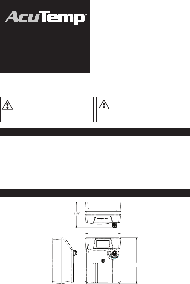
2-3/4"
3-17/32"

2
INSTALLING THE CONTROL
5 Remove the knockout and replace it with the
plastic bushing.
NOTE: For line voltage applications replace the
knockout with proper conduit in accordance with
all applicable codes and ordinances.
1 Locate the immersion well in the tank that is
designed for the temperature control.
2 Hold the AcuTemp control onto the well and
tighten the screw at the base of the control.
3 Slide the sensor into the well. NOTE: two
sensor diameters (3/8" & 1/4") are available to
accommodate different well sizes.
WARNING: The sensor must be fully inserted and fit snugly in the well for proper operation.
If a smaller sensor is used or the sensor is not fully inserted overheating and scalding could result.
4 Trim the sensor wire to the required length (if
needed). Plug the sensor wire into the sensor
input. The terminals are not polarity sensitive.
NOTE: Be sure the wires are fully inserted into the
sensor input.
3A Sensor and Well
(remote mounted control)
1. Insert the sensor all the way into the well.
2. Install the rubber well cap onto the sensor wire
and slide to cover the end of the well
3
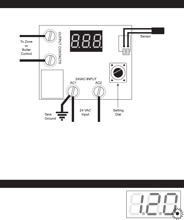
DISPLAY
During normal operation the control will display the temperature set
point. If the control is calling for heat, the decimal point in the bottom
right of the display will light. When the tank temperature is satisfied,
the decimal will turn off.
Calling for Heat
WIRING THE CONTROL
1 Connect the 24 VAC power source to the
“24 VAC Input” terminals (24 VAC transformer
field supplied).
Connect 24 VAC hot to terminal AC2 and 24 VAC
common to AC1. Be sure the AC1 terminal is also
electrically connected to the tank/system ground.
2 Connect the “Output Contacts” to the zone or
boiler control’s domestic water input.
NOTE: The “Output Contacts” are isolated dry
contacts that close when the control calls for
heat.
REFER TO “WIRING THE CONTROL” BELOW OR YOUR TANK MANUAL FOR WIRING INSTRUCTIONS.

4
SETTING THE CONTROL
Push the setting dial to enter the Temperature Setting mode. When pressed,
the display will show ‘OFF’ or the current temperature setting. Turn the dial
to select the desired water temperature to be maintained in the water heater.
See Commercial/Residential (below) for available temperature ranges. The
display will return to the operating mode after five seconds of inactivity.
IMPORTANT: Temperature variations can exist within the water heater. The
value displayed on the control is the approximate temperature. A typical
starting adjustment point is 120°F. Test the water at the closest point of use
for final control adjustment.
DANGER: Scald Hazard – Exposure to 125°F or hotter water can cause
scalding injuries. A mixing valve should be installed on installations
where point of use water temperatures are 125°F or higher.
Temperature Differential The differential does not need to be set.
The AcuTemp’s advanced software algorithm determines the optimum
temperature to initiate heat calls.
Celsius / Fahrenheit To change from Fahrenheit to Celsius, push and hold the setting dial for 5
seconds. The current selection, “F” or “c” will blink on the LED display. Release and turn the setting dial to
the desired setting “F” or “c” then push the setting dial again to select it. NOTE: When the control is set for
Celsius, the display will include a “c” following the temperature. Once selected, the display will return to the
operating mode.
Residential / Commercial The control is equipped with two temperature ranges: One for
residential installations (60°F-160°F)* and a second for commercial installations (60°F-180°F). NOTE: Not
available on all models. To change from the Residential range to the Commercial range, remove power
from the control. Then push and hold the setting dial while restoring power. The current range, “r” or “c”
will blink in the LED display. Release and turn the setting dial to the desired range “r” or “c”, then push
the setting dial again to enter the setting. Once entered, the display will briefly show the selected setting;
then the control will display “off”. Follow the instructions above (Setting the Control) to set the desired
temperature within the selected (residential or commercial) range.
*Note: Some models have a max set point less than 160°F. See ratings section on page 1 for details.
Error Codes
Sensor Error The resistance value of the sensor is out of range. Check the sensor connection to
the pc board. If the connection is good, the sensor may need to be replaced.
--- Self Test Error The control has failed an internal test of the hardware or software. Try cycling
24 VAC power off and on. If the problem is resolved, the control will return to
normal operation. If the error does not clear, the control should be replaced.
Water temperature over 125°F (52°C) can
cause severe burns instantly resulting
in severe injury or death.
Children, the elderly, and the physically
or mentally disabled are at highest risk
for scald injury.
Feel water before bathing or showering.
Temperature limiting valves are available.
126 Bailey Road
North Haven, CT 06473
Phone (203) 776-0473 • FAX (203) 764-1711
www.hydrolevel.com
