
Pub No. 11-HD19D1-1D-EN
Part No. 37-7777006
September 2020
American Standard
Programmable Thermostat
ALL phases of this installation must comply with NATIONAL, STATE AND LOCAL CODES
IMPORTANT — This Document is customer property and is to remain with this unit.
These instructions do not cover all variations in systems or provide for every possible contingency to be met in connection with
the installation. Should further information be desired or should particular problems arise which are not covered sufficiently
for the purchaser’s purposes, the matter should be referred to your installing dealer or local distributor.
ACONT203AS42MA
Installation and User Guide
Installation and User Guide
2 Pub. No. 11-HD19D1-1D-EN 09/2020 Part No. 37-7777006
WARNING
!
FAILURE TO READ AND FOLLOW ALL INSTRUCTIONS
CAREFULLY BEFORE INSTALLING OR OPERATING THIS
CONTROL COULD CAUSE PERSONAL INJURY AND/OR
PROPERTY DAMAGE.
This information is intended for use by individuals possessing
adequate backgrounds of electrical, mechanical, HVAC and
experience. Any attempt to repair a HVAC system may result
in personal injury and/or property damage. The manufacturer
or seller cannot be responsible for the interpretation of this
information, nor can it assume any liability in connection with its
use.
LIVE ELECTRICAL COMPONENTS!
During installation, testing, servicing, and troubleshooting of
this product, it may be necessary to work with live electrical
components. Failure to follow all electrical safety precautions
when exposed to live electrical components could result in death
or serious injury.
Do not use on circuits exceeding specified voltage. Higher
voltage will damage control and could cause shock or fire
hazard.
Do not short out terminals on gas valve or primary control
to test. Short or incorrect wiring will burn out thermostat
and could cause personal injury and/or property damage.
▲
CAUTION
!
To prevent electrical shock and/or equipment damage, disconnect
electric power to system at main fuse or circuit breaker box until
installation is complete.
To prevent compressor and/or property damage, if the outdoor
temperature is below 55°F, DO NOT operate the cooling system. Do
not allow the compressor to run unless the compressor oil heaters
have been operational for six hours and the system has not been
operational for at least five minutes.
ATTENTION: MERCURY NOTICE
This product does not contain mercury. However, this product may
replace a product that contains mercury.
Mercury and products containing mercury must not be discarded in
household trash. Do not touch any spilled mercury. Wearing non-
absorbent gloves, clean up any spilled mercury and place in a sealed
container. For proper disposal of a product containing mercury or a
sealed container of spilled mercury, place it in a suitable shipping
container. Refer to www.thermostat-recycle.org for location to send the
product containing mercury.
1. Safety ................................................................................ 2
2. Product Specifications ................................................... 3
3. General Information ........................................................ 3
3.1 Overview .............................................................. 3
3.2 Contents ............................................................... 3
3.3 Accessories ......................................................... 3
4. Installation ....................................................................... 3
4.1 Location ............................................................... 4
Figure 1: Placement
4.2 Mounting .............................................................. 4
4.3 Battery Location .................................................. 4
4.4 Battery Replacement........................................... 4
4.5 Wiring Diagrams .................................................. 5
1 or 2 Stage Heat Pump with TAM7/TAM9 (24V Mode) 5
1 or 2 Stage Cooling with TAM7/TAM9 (24V Mode) 5
1 Stage Cooling with GAF2-S 6
1 or 2 Stage Cooling with SV92 Furnace 6
1 or 2 Stage Heat Pump with S9V2 Furnace 7
1 Stage Heat Pump with Variable Speed Gas Furnace 7
1 or 2 Stage Heat/Cool Package with Variable Speed Blower 8
1 or 2 Stage Heat Pump Package with Non VSB 8
1 Stage Heat Pump with Non Variable Speed Blower 9
1 or 2 Stage Heat/Cool Package 9
1 or 2 Stage Cooling with TEM 6 VS Gas Furnace 10
1 Stage Cooling with GAT2, GAM2 & TEM3, 4 10
2 Stage heat Pump with GAM5B 11
1 Stage Heat Pump with GAF2-S 11
1 Stage Heat Pump with GAT2, GAM2, TEM3, TEM4 12
1 or 2 Stage Heat Pump with GAM5A or TAM4 or GAF2-36M 12
1 Stage Cooling with GAF2-s 13
4.6 Installer Menu .................................................... 14
5. Test Modes
5.1 Fan Operation .................................................... 15
5.2 Heating System ................................................. 15
5.3 Auxiliary System ............................................... 15
5.4 Cooling System ................................................. 15
6. Thermostat Overview
6.1 User Menu ......................................................... 16
6.2 Thermostat Operation ....................................... 17
6.3 Scheduling ......................................................... 18
6.4 Modifying the Heating Schedule ...................... 18
6.5 Modifying the Cooling Schedule ...................... 18
6.6 Thermostat Settings .......................................... 18
7. Troubleshooting ............................................................ 19
Contents
1. Safety

American Standard 203 Programmable Thermostat
Pub. No. 11-HD19D1-1D-EN 09/2020 Part No. 37-7777006 3
SPECIFICATION DESCRIPTION
Product Models ACONT 203
Product 203
Size 3-3/4” x 6” x 1-1/8” (HxWxD)
Configurations Heat Pump, Heat/Cool, Dual Fuel, Dual Fuel Low Unrestricted Mode Only
Maximum Number of Stages 4 Stages Heat, 2 Stages Cooling
Operating Temperature 32°F to 105°F (0 to +41°C) / 90% RH Non Condensing
Shipping Temperature Range -20 to 150°F (-29 to +65°C)
Input Power (DC) Two 1.5V AA Alkaline
Input Power (AC) 20-30 VAC, NEC Class ll, 50/60 HZ
Terminal Load 1.5A per terminal, 2.5A maximum all terminals combined
Wire Usage 18 AWG
System Modes Auto, Heating, Cooling, Off, Emergency Heat
Fan Modes Auto, On, Program
Indoor Temperature Display Range 32°F to 99°F
RATED DIFFERENTIALS
Fast Medium Slow
Heat (Conventional Gas/Oil/Electric or HP Aux) 0.5°F 0.75°F 1.9°F
Central Air (Cool ) or HP (Heat/Cool) 0.9°F 1.2°F 1.7°F
THERMOSTAT APPLICATION GUIDE
Thermostat Configuration Options Thermostat Applications Maximum Stages Heat/Cool
Single Stage 1 No Heat Pump
Gas, Oil, Electric, Heat Only, Cool Only or
Heat/Cool Systems, 2 or 3 wire Hydronic
Zone (Hot Water or Steam) Systems, 24 Volt
or Millivolt
1+1
Multi Stage 2 No Heat Pump 2+2
Heat Pump 1
Single Stage Compressor Heat Pump
Single Stage Compressor Heat Pump
Systems - up to 2 Stages Aux./Emergency
Heat
3+1
Heat Pump 2
Two Stage or Two Compressor Heat Pump
Two Stage or Two Compressor Heat Pump
systems - up to 2 Stages Aux./Emergency
Heat
4+2
*On every application, 24VAC loads should be reviewed to be sure the indoor unit control power transformer is adequately sized.
NOTE:
Use 18-gauge color-coded thermostat cable for proper wiring. Shielded cable is not typically required.
Keep this wiring at least one foot away from large inductive loads such as Electronic Air Cleaners, motors, line starters, lighting ballasts and
large distribution panels. Failure to follow these wiring practices may introduce electrical interference (noise) which can cause erratic system
operation.
All unused thermostat wire to be grounded at indoor unit chassis ground only. Shielded cable may be required if the above wiring guidelines
cannot be met. Ground only one end of the shield to the system chassis.
2. Product Specifications
3. General Information
3.1 Overview
The 203 is a programmable push button thermostat with
a 3.5’’ backlit display. The 203 features a scheduling mode
that can operate a 7-day program, 5-1-1 program or operate
in a non-programmable mode.
3.2 Contents
— 1-Thermostat
— 1-Sub-base
— 2-Phillips slotted head mounting screws
— 2-Nylon Drywall Anchors
— 1-Installation Guide / User Guide
3.3 Accessories
Wall Cover Plate (BAYCOVR200A)
4. Installation
4.1 Location
The 203 is designed for installation in climate controlled living
spaces. Place the unit in a central location with good circulation.
For proper temperature sensing, avoid exposing the 203 to heat
radiated from lamps, sun light, fireplaces or any other radiant heat
source.
Avoid locations close to windows, behind doors or alcoves with
poor air circulation, adjoining outside walls, or doors that lead to
the outside.
Select a location that prevents the 203 from being directly exposed
to air currents from supply registers or ceiling fans.
Mount the Control on a section of interior wall that does not
contain hot or cold water pipes or duct work.

Installation and User Guide
4 Pub. No. 11-HD19D1-1D-EN 09/2020 Part No. 37-7777006
FIGURE 1. PLACEMENT OF THE 203
Incorrect
Placement
Ceiling Fan
Natural heat
dissipation
from the
thermostat
Onboard
Thermistor
5 FEET
Optimum
Zone
2 FEET
Correct
Placement
Heat from the screen may be trapped
within the body of the Control by an
external top-down airflow source, such
as a ceiling fan.
The onboard thermistor may be biased
by this heat causing the displayed
indoor temperature to be elevated.
4.2 Mounting / Installation
Follow these steps to mount the 203 Control to the wall.
1. Turn OFF all power to heating and cooling equipment.
2. If an existing thermostat is being replaced:
a. Record color and terminal marking of each wire.
b. Disconnect the wires from the existing thermostat
being careful not to allow them to fall back into the wall.
c. Remove the existing thermostat from the wall.
3. Pull the thermostat body off the thermostat base. Forcing
or prying on the thermostat will cause damage to the unit.
4. Move base over hole in wall and mark mounting hole
locations on wall using base as template. (See Fig. 1)
5. Move base out of the way. Drill mounting holes. If you are
using existing mounting holes pull thermostat wire bundle
through the hole in the thermostat base. Secure sub-base
to the wall. Leveling is for appearance only and will not
affect thermostat operation.
6. Connect wires to terminal block on base using appropriate
wiring diagram.
7. Push excess wire into wall and plug hole with a fire resistant
material (such as fiberglass insulation) to prevent drafts
from affecting thermostat operation.
8. Two “AA” alkaline batteries are included in the thermostat
at the factory with a battery tag to prevent power drainage
9. Remove the battery tag to engage the batteries
4.3 Battery Location
FIGURE 2.
Leveling Thermostat
Leveling is for appearance
only and will not aect
thermostat operation.
FIGURE 3.
BATTERY LOCATION
Premium AA alkaline batteries are
required when C-wire is not available.
When C-wire is available, the batteries
provide a back-up source of power (this
will maintain the clock in the event of a
power outage).
RC/RH Jumper Wire
This thermostat electrically
connects the RC and RH
terminals so a jumper
wire is not required. If the
application provides a
separate wire for RC and
RH, clip the RC/RH jumper.
This will isolate both
terminals so they can be
independently used.
4.4 Battery Replacement
To replace batteries, set system to OFF, remove thermostat from wall and install the batteries in the rear along the bottom of the
thermostat (see Figure 3). For best results, use a premium brand “AA” alkaline battery such as Duracell
®
or Energizer
®
. If the home is
going to be unoccupied for an extended period (over 3 months) and “
” is displayed the batteries should be replaced before leaving.
IMPORTANT:
• Do not exceed the specification
ratings.
• All wiring must conform to local
and national electrical codes
and ordinances.
• This control is a precision
instrument, and should be
handled carefully. Rough
handling or distorting
components could cause the
control to malfunction
American Standard 203 Programmable Thermostat
Pub. No. 11-HD19D1-1D-EN 09/2020 Part No. 37-7777006 5
4.5 Wiring Diagrams
NOTES:
1) Wire third party condensate overow
switches between Y of the thermostat
and Y1 of the airow control board
2) X2 is required to energize aux heat
during defrost
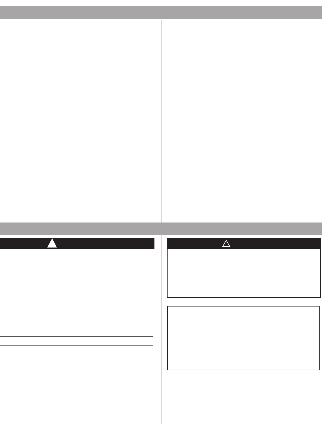
1 or 2 Stage Heat Pump with TAM7/TAM9 (24V Mode)
Indoor Unit Outdoor UnitThermostat
Rc
Rh
O/B
Y
G
W/E
C
L
Y2
W2
R R
OO
Y1
G
W1
B
Y0
Y2
W2
W2
W2
W3
W2
BK
B
X2
Y/Y1
Y2
NOTES:
1) Y1 and Y0 connections must be made as shown
for freeze protection and internally mounted
condensate overow circuits to function properly.
2) Wire third party condensate overow switches
between Y of the thermostat and Y1 of the airow
control board
1 or 2 Stage Cooling with TAM 7/TAM 9 (24V Mode)
Indoor Unit Outdoor UnitThermostat
Rc
Rh
O/B
Y
G
W/E
C
L
Y2
W2
R R
O
Y1
G
W1
B
Y0
Y2
W2
W2
W2
W3
W2
BK
B
Y/Y1
Y2

Installation and User Guide
6 Pub. No. 11-HD19D1-1D-EN 09/2020 Part No. 37-7777006
G
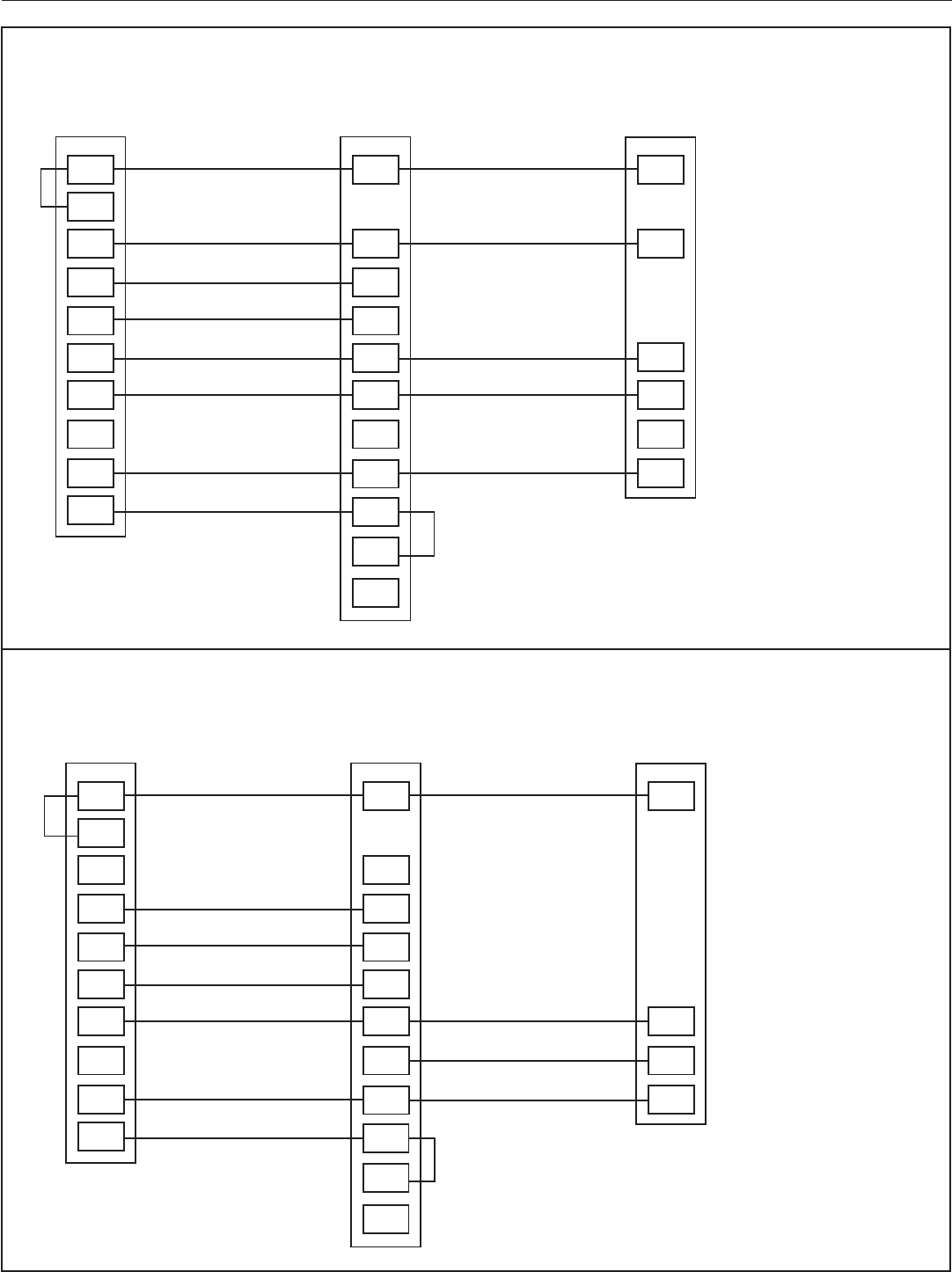
NOTES:
1) Wire third party condensate overow
switches between Y of the thermostat
and Y1 of the airow control board
2) X2 is required to energize aux heat
during defrost
Cooling with GAF2-S
Indoor Unit Outdoor UnitThermostat
Rc
Rh
O/B
Y
G
W/E
C
L
Y2
W2
R
W1
B
B
Y
NOTES:
1) Wire third party condensate overow
switches between Y of the thermostat and
Y1 of the airow control board.
1 or 2 Stage Cooling with SV92 Furnace
Indoor Unit Outdoor UnitThermostat
Rc
Rh
O/B
Y
G
W/E
C
L
Y2
W2
R R
Y1
G
W1
B
Y2
W2
W2
W2
W3
W2
BK
B
Y2
Y/Y1

American Standard 203 Programmable Thermostat
Pub. No. 11-HD19D1-1D-EN 09/2020 Part No. 37-7777006 7
NOTES:
1) Wire third party condensate overow
switches between Y of the thermostat
and Y1 of the airow control board
2) X2 is required to energize aux heat
during defrost
1 or 2 Stage Heat Pump with S9V2 Furnace
Indoor Unit Outdoor UnitThermostat
Rc
Rh
O/B
Y
G
W/E
C
L
Y2
W2
R R
OO
Y1
G
W1
B
Y2
W2
W2
W2
W3
W2
BK
B
X2
Y2
Y/Y1
NOTES:
1) Wire third party condensate overow
switches between Y of the thermostat
and Y1 of the airow control board
2) X2 is required to energize aux heat
during defrost
Heat Pump with Variable Speed Gas Furnace
Indoor Unit Outdoor UnitThermostat
Rc
Rh
O/B
Y
G
W/E
C
L
Y2
W2
R R
O
Y
G
W1
B
W2
W2
B
X2
Y

Installation and User Guide
8 Pub. No. 11-HD19D1-1D-EN 09/2020 Part No. 37-7777006
NOTES:
1) Wire third party condensate overow
switches between Y of the thermostat
and Y1 of the airow control board
2) X2 is required to energize aux heat
during defrost
1 or 2 Stage Heat/Cool Package with Variable Speed Blower
Indoor UnitThermostat
Rc
Rh
O/B
Y
G
W/E
C
L
Y2
W2
R
Y1
G
W1
B
Y2
W2
W2
BK
NOTES:
1) Wire third party condensate overow
switches between Y of the thermostat
and Y1 of the airow control board
2) X2 is required to energize aux heat
during defrost
1 or 2 Stage Heat Pump Package with Variable Speed Blower
Indoor UnitThermostat
Rc
Rh
O/B
Y
G
W/E
C
L
Y2
W2
R
Y1
G
W1
B
Y2
W2
W2/X2
O/B

American Standard 203 Programmable Thermostat
Pub. No. 11-HD19D1-1D-EN 09/2020 Part No. 37-7777006 9
NOTES:
1) Wire third party condensate overow
switches between Y of the thermostat
and Y1 of the airow control board
2) X2 is required to energize aux heat
during defrost
Heat Pump Package Unit with Non Variable Speed Blower
Indoor UnitThermostat
Rc
Rh
O/B
Y
G
W/E
C
L
Y2
W2
R
Y1
G
W1
B
Y2
W2
W2/X2
O/B
NOTES:
1) Wire third party condensate overow
switches between Y of the thermostat
and Y1 of the airow control board
2) X2 is required to energize aux heat
during defrost
1 or 2 Stage Heat/Cool Package
Indoor UnitThermostat
Rc
Rh
O/B
Y
G
W/E
C
L
Y2
W2
R
Y1
G
W1
B
W2
W2
Y2

Installation and User Guide
10 Pub. No. 11-HD19D1-1D-EN 09/2020 Part No. 37-7777006
NOTES:
1) Wire third party condensate overow
switches between Y of the thermostat
and Y1 of the airow control board
2) X2 is required to energize aux heat
during defrost
1 or 2 Stage Cooling with TEM 6 or Variable Speed Gas Furnace
Indoor Unit Outdoor UnitThermostat
Rc
Rh
O/B
Y
G
W/E
C
L
Y2
W2
R R
Y2
Y1
G
W1
B
W2
W2
W2
W3
W2
BK
B
Y2
Y/Y1
NOTES:
1) Wire third party condensate overow
switches between Y of the thermostat
and Y1 of the airow control board
2) X2 is required to energize aux heat
during defrost
Cooling with GAT2, GAM2 & TEM3, 4
Indoor Unit Outdoor UnitThermostat
Rc
Rh
O/B
Y
G
W/E
C
L
Y2
W2
R
G
W1
B
W3
W2
W2
B
Y/Y1

American Standard 203 Programmable Thermostat
Pub. No. 11-HD19D1-1D-EN 09/2020 Part No. 37-7777006 11
NOTES:
1) Wire third party condensate overow
switches between Y of the thermostat
and Y1 of the airow control board
2) X2 is required to energize aux heat
during defrost
2 Stage Heat Pump with GAM5B
Indoor Unit Outdoor UnitThermostat
Rc
Rh
O/B
Y
G
W/E
C
L
Y2
W2
R
O
G
W1
B
W3
W2
W2
B
X2
Y/Y1
R
Y2
NOTES:
1) Wire third party condensate overow
switches between Y of the thermostat
and Y1 of the airow control board
2) X2 is required to energize aux heat
during defrost
Heat Pump with GAF2-S
Indoor Unit Outdoor UnitThermostat
Rc
Rh
O/B
Y
G
W/E
C
L
Y2
W2
R
O
G
W
B
B
X2
Y/Y1
R

Installation and User Guide
12 Pub. No. 11-HD19D1-1D-EN 09/2020 Part No. 37-7777006
NOTES:
1) Wire third party condensate overow
switches between Y of the thermostat
and Y1 of the airow control board
2) X2 is required to energize aux heat
during defrost
Heat Pump with GAT2, GAM2, TEM3, TEM4
Indoor Unit Outdoor UnitThermostat
Rc
Rh
O/B
Y
G
W/E
C
L
Y2
W2
R
O
G
W
B
B
X2
Y/Y1
R
W2
W2
NOTES:
1) Wire third party conden-
sate overow switches
between Y of the thermo-
stat and Y1 of the airow
control board
2) X2 is required to energize
aux heat during defrost
1 or 2 Stage Heat Pump with GAM5A OR TAM4 OR GAF2-36M
Indoor Unit Outdoor UnitThermostat
Rc
Rh
O/B
Y
G
W/E
C
L
Y2
W2
R
O
G
W1
B
B
X2
Y/Y1
R
W2
W3
Y2
Y2
Y0
O
Y1

American Standard 203 Programmable Thermostat
Pub. No. 11-HD19D1-1D-EN 09/2020 Part No. 37-7777006 13
G
NOTES:
1) Wire third party condensate overow
switches between Y of the thermostat
and Y1 of the airow control board
2) X2 is required to energize aux heat
during defrost
Cooling with GAF2-S
Indoor Unit Outdoor UnitThermostat
Rc
Rh
O/B
Y
G
W/E
C
L
Y2
W2
R
W1
B
B
Y

Installation and User Guide
14 Pub. No. 11-HD19D1-1D-EN 09/2020 Part No. 37-7777006
4.6 Installer Menu
To prevent changes that may affect system performance, this thermostat has an INSTALLER MENU and a USER MENU. The
INSTALLER MENU provides access to every option, while the USER MENU provides access to items that will not affect system
performance. To access the INSTALLER MENU press the Menu button for 8 seconds. The display will show item 05 in the table below.
Use Next and back to navigate through menu items. Press or or to change a menu setting.
INSTALLER MENU
(HOLD MENU 8 SEC-
ONDS)
DESCRIPTION DEFAULT SETTING
(FLASHING ICONS)
SETTINGS
(PRESS OR )
05
Outdoor Equipment: selects air conditioner (AC) or heat
pump (HP) equipment as well as the number of stage
AC2
AC0
AC1
AC2
HP1
HP2
10
Indoor Equipment: selects whether the equipment is a
gas furnace, electric furnace or fan only
EL2
FAN
GA1
GA2 (conventional only)
EL1
EL2 (conventional only)
15 dE
Dedicated Emergency: W/E only operates in Emergency
Aux mode. W2 becomes 1st stage Aux. Heat
OFF
On
OFF
20 R
O,B or 3 Wire Zone Valve Selection O
O
B
3
25 Fn
Circulation fan: sets the minimum % of time for the fan
to run (takes into account the fan run time with heat/cool
equipment)
OFF OFF, 10 TO 100
30 CR
Heat Cycle Rate: how often the heat will turn on MEd
SLO – slow
MEd – medium
FAS – fast
32 CR
Aux Cycle Rate: how often the auxiliary heat will turn on MEd
SLO – slow
MEd – medium
FAS – fast
35 CR
Cool Cycle Rate: how often the cooling will turn on MEd
SLO – slow
MEd – medium
FAS – fast
50 CL
Compressor Lockout:
protects the compressor from short cycling
ON
On – 5 minute delay
OFF – no delay
65
Max Heat Limit: maximum set point for heat mode 99 47 to 99
66
Minimum Cool Limit: minimum set point for cool mode 45 45 to 97
74
Schedule Type: set as either 7-Day, 5-1-1 Day or Non-
Programmable
5
7 – 7 Day
5 – 5-1-1 Day
0 – Non Programmable
75
Defines periods per day 4
2 – P1, P2
4 – P1, P2, P3, P4
76 E
Early Start: starts heating or cooling early so your
programmed temperature is reached by the programmed
time
OFF
On – start early
OFF – start at program
period time
79
Fahrenheit or Celsius °F
°F – Fahrenheit
°C – Celsius
81
Temperature Display Adjustment: adjust the displayed
“Room Temperature”
0 -5 to +5
83 dL
Continuous Display Light: keep the backlight always on –
“C” wire required
OFF
On – always on
OFF – momentarily
86
Change Air Filter: set up a monthly reminder OFF
1 to 12 – reminder time
(months)
OFF – no filter reminder
88
Auto Changeover: thermostat automatically switches
between heat and cool
OFF
On – enable auto
OFF – disable auto
99
Keypad Lock: prevent unwanted changes to the
thermostat
OFF
On – disable buttons
OFF – all buttons are active

American Standard 203 Programmable Thermostat
Pub. No. 11-HD19D1-1D-EN 09/2020 Part No. 37-7777006 15
5. Test Modes
Turn on power to the system.
5.1 Fan Operation
If your system does not have a G terminal connection, skip to
Heating System.
1.) Press the fan button to select the On position. The blower
should begin to operate.
2.) Press the fan button to select the Auto position. The blower
should stop immediately.
NOTE: when “Circulation Fan” setting is being used, the fan will
run for at least that percentage of time taking into account
the heating and cooling run time (fan button must be in
Auto position). When in use, “FAn” will appear on the home
screen (momentarily replacing the displayed time).
5.2 Heating System
1.) Press the System button to select the Heat position. Heat
Pumps only - if the auxiliary heating system has a standing
pilot, be sure to light it.
2.) Press to adjust thermostat setting to 1° above room
temperature. The heating system should begin to operate
and the thermostat will indicate Heat On.
3.) For heat pump with auxiliary- Press to adjust thermostat
setting to 3° above room temperature. The auxiliary heat
should begin to operate and the thermostat will indicate
Heat On Aux.
4.) Press to adjust thermostat setting 1° below room
temperature. The heating system should stop operating and
the Heat On icon will disappear.
1 Note: If Starting Soon is shown on the display, the compressor lockout feature is operating. There will be up to a 5 minute delay before the
compressor turns on (see Installer Menu, item 50)
5.3 Auxiliary System ( only for heat
pumps with auxiliary)
1.) Press the System button to select the Aux position.
2.) Press to adjust thermostat setting to 1° above room
temperature. The auxiliary heating system should begin to
operate and the thermostat will indicate Heat On Aux.
3.) Press to adjust thermostat setting 1° below room
temperature. The auxiliary heating system should stop
operating and the Heat On Aux icon will disappear.
5.4 Cooling System
1.) Press the System button to select the Cool position.
2.) Press to adjust thermostat setting 1° below room
temperature. The blower should come on immediately on
high speed, followed by cold air circulation. The thermostat
will indicate Cool On. There can be up to a 5 minute delay.
(see INSTALLER MENU, item 50)
3.) Press to adjust thermostat setting to 1° above room
temperature. The cooling system should stop operating and
the Cool On icon will disappear.
1

Installation and User Guide
16 Pub. No. 11-HD19D1-1D-EN 09/2020 Part No. 37-7777006
6. Thermostat Overview
Before you begin using your thermostat, you should be familiar with its features, display and the location/operation of the thermostat
buttons and switches.
THERMOSTAT BUTTONS AND SWITCHES THE DISPLAY
1.) Fan Button 8.) Next (Menu button) is used to navigate within a menu
2.) Hold a permanent temperature or press again to cancel
hold (return to programmed schedule)
9.) Set the correct time, access the schedule and customize thermostat settings
3.) System Button 10.) Back (Fan button) is used to navigate within a menu
4.) Backlight Button (located on the top of the thermostat) 11.) Exit (Hold/Run button) returns to the home screen
5.) Raises Temperature Setting 12.) Thermostat is protecting the equipment from short cycling (5-minute delay)
6.) Access Menu Options
13.) Indicates that the system is running in Cool, Heat or Auxiliary mode. (Heat Pump
Only -The auxiliary will run in Heat mode when the heat pump cannot maintain
the set temperature.)
7.) Lowers Temperature Setting
14.) SEE TROUBLESHOOTING
15.) Battery status indicator
16.) Replace battery indicator
17.) Day of the week used when programming a schedule
18.) Permanent hold (bypassing the schedule)
19.) Temperature set point
20.) Appears when the keypad is locked (to prevent unwanted changes)
1
2
3
4
5
6
7
8
9
11
12
13
14
15
16
17
18
19
20
10
Whenever“
Replace
” appears in the display, new premium brand AA alkaline batteries should be installed. If the house will be
unoccupied for an extended period and either “ ” or “
Replace
” is displayed, install new batteries before leaving.

American Standard 203 Programmable Thermostat
Pub. No. 11-HD19D1-1D-EN 09/2020 Part No. 37-7777006 17
6.2 Thermostat Operation
Set Current Time and Day
Note: Time icons will flash at initial power up or after a reset.
1.) Press Menu
2.) The time icon will be flashing. Press Next to advance and set
the time
3.) Use or to set the correct time
4.) Press Next and use or to set the correct day
5.) Press Exit when finished.
The default program is 5-1-1 Day, but can be setup as a 7-Day or
Non-Programmable thermostat (refer to the User Menu above).
• Hold Temperature (bypassing the schedule) – With
the System set to Heat or Cool, momentarily press the
Hold/Run button. Hold will be displayed. Use or
to adjust the temperature. The thermostat will hold the
room temperature at the selected setting until you press
Hold/Run again to start program operation (cancels
permanent Hold).
• Program Override (Temporary Hold) – Press or
until the desired temperature is displayed. The
thermostat will override the schedule until the next
programmed time period with a minimum override of 2
hours. Then the thermostat will automatically revert to
the program.
• Keypad Lockout – To prevent unwanted changes,
the buttons can be disabled. To turn this feature On,
press and hold and the Menu button until the icon
appears. To turn Off, press and hold and the Menu
button for 3 seconds.
• Circulation fan - makes sure the air is being re-
circulated by establishing a minimum run-time for the
fan regardless of whether the heating and cooling
equipment is running. When in use, “FAn” will appear on
the home screen (momentarily replacing the displayed
time). Choosing a setting of 30% will ensure the fan runs
at least 30% in a day, taking into account the time the
fan has run during any heating or cooling event.
6.1 User Menu
To customize thermostat settings, press the Menu button from the home screen. Use the or buttons to highlight Settings and press
Next. Use Next and Back to navigate through menu items. Press or to change the setting.
USER’S MENU #
(PRESS MENU BUT-
TON AND RELEASE)
DESCRIPTION
DEFAULT SETTING
(FLASHING ICONS)
SETTINGS
(PRESS OR )
01
Schedule Type: set as either 7-Day,
5-1-1 Day or Non Programmable
5
7 – 7 Day
5 – 5-1-1 Day
0 – Non-Programmable
02
Defines periods per day 4
2 - P1, P2
4 - P1, P2, P3, P4
03 E
Early Start: starts heating or
cooling early so your programmed
temperature is reached by the
programmed time
OFF
On – start early
OFF – start at program
period time
04 Fn
Circulation Fan: sets the minimum %
of time for the fan to run (takes into
account the fan run time with heat/
cool equipment)
OFF
OFF, 10 to 100
05
Fahrenheit or Celsius °F
°F – Fahrenheit
°C – Celsius
06
Temperature Display
Adjustment: adjust the Room
Temperature)
0 -5 to +5
07 dL
Continuous Display Light: keep
the backlight always on – “C” wire
required
OFF
On – always on
OFF – momentarily
08
Change Air Filter: set up a monthly
reminder
OFF
1 to 12 – reminder time
(months)
OFF – no filter reminder
09
Auto-Changeover: thermostat
automatically switches between heat
and cool
OFF
On - enable auto
OFF - disable auto

Installation and User Guide
18 Pub. No. 11-HD19D1-1D-EN 09/2020 Part No. 37-7777006
6.3 Scheduling
Energy Saving Factory Schedule
This thermostat is programmed with the energy saving settings shown in the table below for all days of the week
P1/WAKE P2/LEAVE P3/RETURN P4/SLEEP
Heating Schedule 6:00 AM - 70°F 8:00 AM - 62°F 5:00 PM - 70°F 10:00 PM - 62°F
Cooling Schedule 6:00 AM - 78°F 8:00 AM - 85°F 5:00 PM - 78°F 10:00 PM - 82°F
Note:Thermostatcanbeprogrammedonorothesubbase
6.4 Modify the Heating Schedule
1.) Use the System button to select Heat
2.) Press Menu
3.) Use the button to select Schedule and press Next to enter the schedule
4.) The time icons will flash – use or to set the time for the start of a period
5.) Press Next – the set point icons will flash – use or to set the temperature for the current period
6.) Continue to press Next to advance through all periods (P1/Wake, P2/Leave, P3/Return, P4/Sleep) for all days of the week.
Note: Press Back to return to the previous setting. Once all days of the week have been programmed the thermostat will display End.
Press Exit at any time to save changes and return to home screen.
6.5 Modify the Cooling Schedule
1.) Use the System button to select Cool
2.) Repeat steps 2-6 from the heating schedule
6.6 Thermostat Settings
Resetting the Thermostat or Thermostat Settings
If the thermostat has good batteries, but has a blank display or does not respond to key presses, the thermostat should be reset by
removing the batteries for 2 minutes. This reset will not change the menu settings or program. If the condition persists after reinstalling
the batteries, replace the thermostat.
To conveniently reset only the schedule and user settings back to factory defaults, press Menu and Backlight buttons at the same time
and hold until the display goes blank and resets.

American Standard 203 Programmable Thermostat
Pub. No. 11-HD19D1-1D-EN 09/2020 Part No. 37-7777006 19
7. Troubleshooting
SYMPTOM POSSIBLE CAUSE CORRECTIVE ACTION
No Heat/
No Cool/
No Fan
(common
problem)
1.) Blown fuse or tripped circuit breaker
2.) Furnace power switch to OFF
3.) Furnace blower compartment door
panel loose or not properly installed
4.) Loose connection to thermostat or
system
1.) Replace fuse or reset breaker
2.) Turn switch to ON
3.) Replace door panel in proper position to engage safety interlock or door switch
4.) Tighten Connections
No Heat
1.) System not set to Heat
2.) Loose connection to thermostat or
system
3.) Heating System requires service or
thermostat requires replacement
1.) Set thermostat to Heat.
2.) Verify thermostat and system wires are securely attached.
3.) Diagnostic: Set System to Heat and raise the set point above room temperature.
Within five minutes the thermostat should make a soft click sound and “Heat On”
should appear on display. This sound indicates the thermostat is operating properly. If
the thermostat does not click, try the reset operation listed below. If the thermostat does
not click after being reset, contact your heating and cooling service person or place of
purchase for a replacement. If the thermostat clicks, contact the furnace manufacturer
or a service person to verify the heating system is operating correctly.
No Cool
1.) System not set to Cool
2.) Loose connection to thermostat or
system
3.) Cooling System requires service or
thermostat requires replacement
1.) Set thermostat to Cool.
2.) Verify thermostat and system wires are securely attached.
3.) Diagnostic: Set System to Cool and lower set point below room temperature. Same
procedures as diagnostic for “No Heat” condition except set the thermostat to Cool and
lower the set point below the room temperature. There may be up to a five minute delay
before the thermostat clicks in Cooling if the compressor lock-out option is selected in
the installer menu. (see INSTALLER MENU, item 50)
Heat, Cool or Fan
Runs Constantly
Possible short in wiring, thermostat, heat,
cool or fan system
Check each wire connection to verify they are not shorted or touching other wires. Try
resetting the thermostat. If the condition persists contact your HVAC service person.
Thermostat
Display &
Thermometer
Disagree
Thermostat display requires adjustment Display can be adjusted +/-5°. See User Menu item 05
Furnace (Air
Conditioner)
Cycles Too
Fast or Slow
(narrow or wide
temperature
swing)
The location of the thermostat and/or
the size of the Heating System may be
influencing the cycle rate
Digital thermostats provide precise control and cycle faster than older mechanical
models. The system turns on and off more frequently, but runs for a shorter time. If
you would like to increase cycle time, choose SLO for slow cycle in the Installer menu.
(Reference menu items 30, 32 & 35.) If an acceptable cycle rate is not achieved,
contact your HVAC service person.
“Call for Service”
icon appears on
displayed
1.) Heating system is not able to heat
the space to within 10 degrees of the set
point within 2 hours
2.) Cooling system is not able to cool
the space to within 10 degrees of the set
point within 2 hours
3.) If “--” is displayed for the Room
Temperature, a replacement thermostat
is needed
4.) None of the buttons operate on the
thermostat
5.) If “Call for Service” is flashing,
compressor self diagnostic is detecting
an issue with the outdoor unit
1.) See corrective action for “No Heat”
2.) See corrective action for “No Cool”
3.) Replace thermostat
4.) Make sure keypad lockout is not turned on ( ), If it’s OFF, try reset shown below.
5.) Contact a service person to verify the outdoor equipment is operating correctly

About American Standard Heating and Air Conditioning
American Standard has been creating comfortable and affordable living environments for more than a century. For more
information, please visit www.americanstandardair.com.
The manufacturer has a policy of continuous data improvement and it reserves the right to change design and specifications without notice. We are
committed to using environmentally conscious print practices.
© 2020 American Standard Heating and Air Conditioning
11-HD19D1-1D-EN (09 Sept 2020)
Supersedes 11-HD19D1-1C-EN (31 July 2019)
