
ventil
Installation Instructions
NOTE: Read the entire instruction manual before starting the
installation.
NOTE: Please refer to the literature provided with the connected HVAC
equipment for more details on system operations with specific pieces of
equipment.
The features and functions outlined in the Installation Instructions reflect
Version 1.3 or later software. See the Infinity System Control product
page on the HVACPartners.com website or the Downloads section of the
www.MyInfinityTouch.Carrier.com website for the latest software
release and literature.
US Patents: Carrier U.S. Pat No. 7,243,004, U.S. Pat No. 7,775,452,
pointSET™ U.S. Pat No. 7,415,102
SYSTXCCITC01-B,
SYSTXCCITC01-C,
SYSTXCCWIC01-B,
SYSTXCCICF01-B,
SYSTXCCWIF01-B
Infinity® System Control
A210174
A170203A
A180218C

2

3
Table of Contents
1. Safety Considerations . . . . . . . . . . . . . . . . . . . . . . . . . . . . . . . . . . . . . . . . . . . . . 7
2. Introduction . . . . . . . . . . . . . . . . . . . . . . . . . . . . . . . . . . . . . . . . . . . . . . . . . . . . . 8
3. Quick Start. . . . . . . . . . . . . . . . . . . . . . . . . . . . . . . . . . . . . . . . . . . . . . . . . . . . . . 8
3.1. Set Time and Date. . . . . . . . . . . . . . . . . . . . . . . . . . . . . . . . . . . . . . . . . . . 9
3.1.1. Manually Adjust Time and Date. . . . . . . . . . . . . . . . . . . . . . . . . . . 9
3.1.2. Setup Time Zone. . . . . . . . . . . . . . . . . . . . . . . . . . . . . . . . . . . . . . . 9
3.1.3. Enable Time Synchronization. . . . . . . . . . . . . . . . . . . . . . . . . . . . . 9
3.2. Set Dealer Information for Series B . . . . . . . . . . . . . . . . . . . . . . . . . . . . 10
4. Installation . . . . . . . . . . . . . . . . . . . . . . . . . . . . . . . . . . . . . . . . . . . . . . . . . . . . . 11
4.1. Overview. . . . . . . . . . . . . . . . . . . . . . . . . . . . . . . . . . . . . . . . . . . . . . . . . 11
4.2. Check Equipment . . . . . . . . . . . . . . . . . . . . . . . . . . . . . . . . . . . . . . . . . . 11
4.3. Location. . . . . . . . . . . . . . . . . . . . . . . . . . . . . . . . . . . . . . . . . . . . . . . . . . 12
4.3.1. Wall Control . . . . . . . . . . . . . . . . . . . . . . . . . . . . . . . . . . . . . . . . . 12
4.3.2. Wired Remote Room Sensors. . . . . . . . . . . . . . . . . . . . . . . . . . . . 13
4.3.2.1. Wired Remote Room Sensor Averaging . . . . . . . . . . . . . . 13
4.3.3. Smart Sensors (for zoning applications). . . . . . . . . . . . . . . . . . . . 14
4.4. Wiring Considerations . . . . . . . . . . . . . . . . . . . . . . . . . . . . . . . . . . . . . . 15
4.4.1. Shielded Wire and Communication Bus Configuration . . . . . . . . 16
4.4.2. Damper Control Module (zoning systems only). . . . . . . . . . . . . . 17
4.5. Decorative Trim Plate . . . . . . . . . . . . . . . . . . . . . . . . . . . . . . . . . . . . . . . 18
4.5.1. Mounting. . . . . . . . . . . . . . . . . . . . . . . . . . . . . . . . . . . . . . . . . . . . 18
4.5.2. System Control Mounting. . . . . . . . . . . . . . . . . . . . . . . . . . . . . . . 19
4.6. Humidifier Connections . . . . . . . . . . . . . . . . . . . . . . . . . . . . . . . . . . . . . 20
4.6.1. Bypass Humidifier . . . . . . . . . . . . . . . . . . . . . . . . . . . . . . . . . . . . 20
4.6.2. Fan Powered Humidifiers . . . . . . . . . . . . . . . . . . . . . . . . . . . . . . . 20
4.7. Ventilator Connections . . . . . . . . . . . . . . . . . . . . . . . . . . . . . . . . . . . . . . 21
4.7.1. Energy Recovery Ventilator . . . . . . . . . . . . . . . . . . . . . . . . . . . . . 21
4.7.2. Heat Recovery Ventilator . . . . . . . . . . . . . . . . . . . . . . . . . . . . . . . 21
5. Commissioning . . . . . . . . . . . . . . . . . . . . . . . . . . . . . . . . . . . . . . . . . . . . . . . . . 21
5.1. Searching for Indoor Unit . . . . . . . . . . . . . . . . . . . . . . . . . . . . . . . . . . . . 21
5.2. Searching for Outdoor Unit. . . . . . . . . . . . . . . . . . . . . . . . . . . . . . . . . . . 22
5.3. Indoor Evaporator Selection . . . . . . . . . . . . . . . . . . . . . . . . . . . . . . . . . . 23
5.4. Electric Heater Selection. . . . . . . . . . . . . . . . . . . . . . . . . . . . . . . . . . . . . 24

4
5.4.1. Hydronic Heat Application. . . . . . . . . . . . . . . . . . . . . . . . . . . . . . 24
5.5. Searching for SAM Module (If Applicable) . . . . . . . . . . . . . . . . . . . . . . 25
5.6. Searching for Zones (If Applicable) . . . . . . . . . . . . . . . . . . . . . . . . . . . . 25
5.7. Filter Type Selection. . . . . . . . . . . . . . . . . . . . . . . . . . . . . . . . . . . . . . . . 26
5.8. Humidifier Installation . . . . . . . . . . . . . . . . . . . . . . . . . . . . . . . . . . . . . . 26
5.9. Ultraviolet Lights Installation . . . . . . . . . . . . . . . . . . . . . . . . . . . . . . . . . 26
5.10. Equipment Summary. . . . . . . . . . . . . . . . . . . . . . . . . . . . . . . . . . . . . . . . 26
5.11. Airflow Verification Check. . . . . . . . . . . . . . . . . . . . . . . . . . . . . . . . . . . 27
5.12. Duct Assessment (zoned systems only) . . . . . . . . . . . . . . . . . . . . . . . . . 28
6. Service Menu. . . . . . . . . . . . . . . . . . . . . . . . . . . . . . . . . . . . . . . . . . . . . . . . . . . 29
6.1. Equipment Summary. . . . . . . . . . . . . . . . . . . . . . . . . . . . . . . . . . . . . . . . 30
6.2. Installation. . . . . . . . . . . . . . . . . . . . . . . . . . . . . . . . . . . . . . . . . . . . . . . . 30
6.3. Set up. . . . . . . . . . . . . . . . . . . . . . . . . . . . . . . . . . . . . . . . . . . . . . . . . . . . 31
6.3.1. Thermostat . . . . . . . . . . . . . . . . . . . . . . . . . . . . . . . . . . . . . . . . . . 32
6.3.1.1. Auto Mode Set Up . . . . . . . . . . . . . . . . . . . . . . . . . . . . . . . 32
6.3.1.2. Heat/Cool Deadband . . . . . . . . . . . . . . . . . . . . . . . . . . . . . 33
6.3.1.3. Offsets. . . . . . . . . . . . . . . . . . . . . . . . . . . . . . . . . . . . . . . . . 33
6.3.1.4. Reset Factory Defaults . . . . . . . . . . . . . . . . . . . . . . . . . . . . 34
6.3.1.5. Scheduling On/Off . . . . . . . . . . . . . . . . . . . . . . . . . . . . . . . 35
6.3.1.6. Smart Recovery On/Off . . . . . . . . . . . . . . . . . . . . . . . . . . . 35
6.3.2. Fan Coil. . . . . . . . . . . . . . . . . . . . . . . . . . . . . . . . . . . . . . . . . . . . . 35
6.3.2.1. Airflow . . . . . . . . . . . . . . . . . . . . . . . . . . . . . . . . . . . . . . . . 35
6.3.2.2. Altitude . . . . . . . . . . . . . . . . . . . . . . . . . . . . . . . . . . . . . . . . 36
6.3.2.3. Dehumidification Options . . . . . . . . . . . . . . . . . . . . . . . . . 37
6.3.2.4. Fan Coil G-Terminal Input. . . . . . . . . . . . . . . . . . . . . . . . . 37
6.3.2.5. Fan Coil G-Terminal Alert . . . . . . . . . . . . . . . . . . . . . . . . . 38
6.3.2.6. Fan Coil G Terminal Alert Label . . . . . . . . . . . . . . . . . . . . 39
6.3.3. Furnace . . . . . . . . . . . . . . . . . . . . . . . . . . . . . . . . . . . . . . . . . . . . . 39
6.3.3.1. Furnace Airflow . . . . . . . . . . . . . . . . . . . . . . . . . . . . . . . . . 39
6.3.3.2. AC/HP Airflow. . . . . . . . . . . . . . . . . . . . . . . . . . . . . . . . . . 40
6.3.3.3. Furnace Staging . . . . . . . . . . . . . . . . . . . . . . . . . . . . . . . . . 41
6.3.3.4. Furnace Airflow Limits (modulating furnace only) . . . . . . 41
6.3.3.5. Furnace Off Delay . . . . . . . . . . . . . . . . . . . . . . . . . . . . . . . 42
6.3.3.6. Altitude . . . . . . . . . . . . . . . . . . . . . . . . . . . . . . . . . . . . . . . . 42
6.3.3.7. Furnace Dehumidifier Drain. . . . . . . . . . . . . . . . . . . . . . . . 42
6.3.3.8. Furnace G Terminal . . . . . . . . . . . . . . . . . . . . . . . . . . . . . . 43

5
6.3.3.9. Furnace G-Terminal Alert . . . . . . . . . . . . . . . . . . . . . . . . . 43
6.3.3.10. Furnace G Terminal Alert Label . . . . . . . . . . . . . . . . . . . . 44
6.3.4. AC/Heat Pump . . . . . . . . . . . . . . . . . . . . . . . . . . . . . . . . . . . . . . . 44
6.3.4.1. Latching . . . . . . . . . . . . . . . . . . . . . . . . . . . . . . . . . . . . . . . 44
6.3.4.2. Cooling Lockout. . . . . . . . . . . . . . . . . . . . . . . . . . . . . . . . . 45
6.3.4.3. Defrost Interval. . . . . . . . . . . . . . . . . . . . . . . . . . . . . . . . . . 46
6.3.4.4. Low Ambient Cooling . . . . . . . . . . . . . . . . . . . . . . . . . . . . 46
6.3.4.5. Quiet Shift . . . . . . . . . . . . . . . . . . . . . . . . . . . . . . . . . . . . . 46
6.3.4.6. AC/Heat Pump RPM Max . . . . . . . . . . . . . . . . . . . . . . . . . 46
6.3.4.7. Defrost Fan Delay. . . . . . . . . . . . . . . . . . . . . . . . . . . . . . . . 47
6.3.4.8. Brownout Disable. . . . . . . . . . . . . . . . . . . . . . . . . . . . . . . . 47
6.3.4.9. Low Air Multiplier . . . . . . . . . . . . . . . . . . . . . . . . . . . . . . . 47
6.3.4.10. Energy Efficiency. . . . . . . . . . . . . . . . . . . . . . . . . . . . . . . . 47
6.3.5. Heat Source Lockout . . . . . . . . . . . . . . . . . . . . . . . . . . . . . . . . . . 47
6.3.6. Stages / Latch for 18VS . . . . . . . . . . . . . . . . . . . . . . . . . . . . . . . . 48
6.3.7. Geothermal HP (when available) . . . . . . . . . . . . . . . . . . . . . . . . . 49
6.3.7.1. Freeze Limits . . . . . . . . . . . . . . . . . . . . . . . . . . . . . . . . . . . 49
6.3.7.2. Lockout Count . . . . . . . . . . . . . . . . . . . . . . . . . . . . . . . . . . 50
6.3.7.3. Brownout Override. . . . . . . . . . . . . . . . . . . . . . . . . . . . . . . 51
6.3.7.4. Geothermal HP Energy Tracking . . . . . . . . . . . . . . . . . . . . 51
6.3.8. Zoning (If Applicable) . . . . . . . . . . . . . . . . . . . . . . . . . . . . . . . . . 51
6.3.8.1. Disable Zoning . . . . . . . . . . . . . . . . . . . . . . . . . . . . . . . . . . 52
6.3.8.2. Zone Offsets . . . . . . . . . . . . . . . . . . . . . . . . . . . . . . . . . . . . 52
6.3.8.3. Airflow Limits . . . . . . . . . . . . . . . . . . . . . . . . . . . . . . . . . . 52
6.3.8.4. Duct Assessment Time . . . . . . . . . . . . . . . . . . . . . . . . . . . . 53
6.3.9. Accessories . . . . . . . . . . . . . . . . . . . . . . . . . . . . . . . . . . . . . . . . . . 53
6.3.9.1. Filter . . . . . . . . . . . . . . . . . . . . . . . . . . . . . . . . . . . . . . . . . . 53
6.3.9.2. Humidifier . . . . . . . . . . . . . . . . . . . . . . . . . . . . . . . . . . . . . 54
6.3.9.3. Ultraviolet Lights . . . . . . . . . . . . . . . . . . . . . . . . . . . . . . . . 54
6.3.9.4. Ventilator . . . . . . . . . . . . . . . . . . . . . . . . . . . . . . . . . . . . . . 55
6.3.10. Utility Curtailment . . . . . . . . . . . . . . . . . . . . . . . . . . . . . . . . . . . . 55
6.3.11. Hydronic Airflow . . . . . . . . . . . . . . . . . . . . . . . . . . . . . . . . . . . . . 56
6.4. Check out . . . . . . . . . . . . . . . . . . . . . . . . . . . . . . . . . . . . . . . . . . . . . . . . 57
6.4.1. Electric Heat . . . . . . . . . . . . . . . . . . . . . . . . . . . . . . . . . . . . . . . . . 58
6.4.2. Furnace . . . . . . . . . . . . . . . . . . . . . . . . . . . . . . . . . . . . . . . . . . . . . 58
6.4.3. Hydronic . . . . . . . . . . . . . . . . . . . . . . . . . . . . . . . . . . . . . . . . . . . . 59
6.4.4. Air Conditioning. . . . . . . . . . . . . . . . . . . . . . . . . . . . . . . . . . . . . . 59

6
6.4.5. Heat Pump Heating. . . . . . . . . . . . . . . . . . . . . . . . . . . . . . . . . . . . 59
6.4.6. Heat Pump Cooling. . . . . . . . . . . . . . . . . . . . . . . . . . . . . . . . . . . . 60
6.4.7. Humidifier. . . . . . . . . . . . . . . . . . . . . . . . . . . . . . . . . . . . . . . . . . . 61
6.4.8. Ventilator . . . . . . . . . . . . . . . . . . . . . . . . . . . . . . . . . . . . . . . . . . . 61
6.4.9. Zoning (If Applicable) . . . . . . . . . . . . . . . . . . . . . . . . . . . . . . . . . 61
6.4.9.1. Airflow Limits . . . . . . . . . . . . . . . . . . . . . . . . . . . . . . . . . . 61
6.4.9.2. Damper/Sensor Check . . . . . . . . . . . . . . . . . . . . . . . . . . . . 62
6.4.9.3. Zone Duct Assessment . . . . . . . . . . . . . . . . . . . . . . . . . . . . 63
6.4.9.4. Sensor Type . . . . . . . . . . . . . . . . . . . . . . . . . . . . . . . . . . . . 63
6.5. Service Information. . . . . . . . . . . . . . . . . . . . . . . . . . . . . . . . . . . . . . . . . 63
6.5.1. Advanced Diagnostics . . . . . . . . . . . . . . . . . . . . . . . . . . . . . . . . . 64
6.5.2. Fan Coil Status . . . . . . . . . . . . . . . . . . . . . . . . . . . . . . . . . . . . . . . 64
6.5.3. Furnace Status. . . . . . . . . . . . . . . . . . . . . . . . . . . . . . . . . . . . . . . . 64
6.5.4. AC Status . . . . . . . . . . . . . . . . . . . . . . . . . . . . . . . . . . . . . . . . . . . 65
6.5.5. Heat Pump Status . . . . . . . . . . . . . . . . . . . . . . . . . . . . . . . . . . . . . 65
6.5.6. Geothermal HP Status. . . . . . . . . . . . . . . . . . . . . . . . . . . . . . . . . . 66
6.5.7. Zoning Status . . . . . . . . . . . . . . . . . . . . . . . . . . . . . . . . . . . . . . . . 66
6.5.8. Last 10 System Events . . . . . . . . . . . . . . . . . . . . . . . . . . . . . . . . . 67
6.5.9. Run/Fault History . . . . . . . . . . . . . . . . . . . . . . . . . . . . . . . . . . . . . 67
6.5.10. Model/Serial Numbers . . . . . . . . . . . . . . . . . . . . . . . . . . . . . . . . . 68
6.5.11. Service Phone Number . . . . . . . . . . . . . . . . . . . . . . . . . . . . . . . . . 68
6.5.12. Energy Tracking . . . . . . . . . . . . . . . . . . . . . . . . . . . . . . . . . . . . . . 68
6.6. Refrigerant Charging: Greenspeed® Intelligence, 18VS™, 19VS™ Sys-
tems 69
6.6.1. Charging . . . . . . . . . . . . . . . . . . . . . . . . . . . . . . . . . . . . . . . . . . . . 69
6.6.2. Pump Down . . . . . . . . . . . . . . . . . . . . . . . . . . . . . . . . . . . . . . . . . 71
6.6.3. Evacuation . . . . . . . . . . . . . . . . . . . . . . . . . . . . . . . . . . . . . . . . . . 71
6.6.4. EXV Position . . . . . . . . . . . . . . . . . . . . . . . . . . . . . . . . . . . . . . . . 72
6.7. Dealer Logo for Series B. . . . . . . . . . . . . . . . . . . . . . . . . . . . . . . . . . . . . 72
6.8. Utility Event Setup . . . . . . . . . . . . . . . . . . . . . . . . . . . . . . . . . . . . . . . . . 74
7. Wireless Set-up . . . . . . . . . . . . . . . . . . . . . . . . . . . . . . . . . . . . . . . . . . . . . . . . . 74
7.1. Setup and Status Information (Homeowner’s Router) . . . . . . . . . . . . . . 75
8. Wiring Diagrams . . . . . . . . . . . . . . . . . . . . . . . . . . . . . . . . . . . . . . . . . . . . . . . . 80
9. Statement Information. . . . . . . . . . . . . . . . . . . . . . . . . . . . . . . . . . . . . . . . . . . . 91
9.1. FCC Interference Statement . . . . . . . . . . . . . . . . . . . . . . . . . . . . . . . . . . 91

7
NOTE: See the Owner’s Manual for information regarding software
upgrades.
1. Safety Considerations
Improper installation, adjustment, alteration, service, maintenance, or use
can cause explosion, fire, electrical shock, or other conditions which may
cause death, personal injury or property damage. Consult a qualified
installer, service agency or your distributor or branch for information or
assistance. The qualified installer or agency must use factory-authorized
kits or accessories when modifying this HVAC system. Refer to the
individual instructions packaged with the kits or accessories when
installing.
Follow all safety codes. Wear safety glasses, protective clothing, and
work gloves. Have a fire extinguisher available. Read these instructions
thoroughly and follow all warnings and cautions included in literature
and attached to the unit. Consult local building codes and the current
edition of the National Electrical Code (NEC) NFPA 70. In Canada, refer
to the current editions of the Canadian Electrical Code CSA C22.1.
Recognize safety information. When you see this symbol on the unit
and in instructions or manuals, be alert to the potential for personal
injury. Understand the signal words DANGER, WARNING, and
CAUTION. These words are used with the safety-alert symbol.
DANGER identifies the most serious hazards, which will result in severe
personal injury or death. WARNING signifies hazards, which could
result in personal injury or death. CAUTION is used to identify unsafe
practices, which may result in minor personal injury or product and
property damage. NOTE is used to highlight suggestions which will
result in enhanced installation, reliability, or operation.

8
2. Introduction
The Infinity® System consists of several intelligent communicating
components which include the Infinity System Control (or User
Interface), variable speed furnace or FE fan coil, 2-stage AC and HP,
(including Geothermal units), multi-stage AC and HP, variable capacity
HP and AC units, and Infinity System Package units which continually
communicate with each other via a four-wire connection called the
ABCD bus. Commands, operating conditions, and other data are passed
continually between components over the ABCD bus. The result is a new
level of comfort, versatility, and simplicity.
All Infinity System furnaces or fan coils are variable-speed and multi
stage for maximum flexibility, efficiency, and comfort. They support
controlled ventilation, humidification, dehumidification, and air quality
control. Either an Infinity System (communicating), or a standard
single-stage 24VAC controlled outdoor unit may be used.
When using conventional single-stage outdoor units, the Infinity System
furnace or fan coil provides the 24 volt signals needed to control them.
When using multi-stage conventional outdoor units or heat pumps, an
Infinity System Network Interface Module or “NIM” (P/N
SYSTXCCNIM01) may be required to provide additional control
outputs. Also, the NIM with a translator board (SYSTXXXTRB01)
allows connection of a Carrier HRV or ERV without the need for separate
wall control.
All system components are controlled through the wall mounted Infinity
System Control, which replaces the conventional thermostat and
provides the homeowner with a single wall control for all features of the
system.
3. Quick Start
NOTE: See Installation Section for installation instructions.

9
3.1. Set Time and Date
The time and date can either be set manually or can be synchronized with
the web server. From the main screen, touch MENU, on the bottom of
the control. The TIME/DATE icon will bring up the time and date menu.
A14215
3.1.1. Manually Adjust Time and Date
• To set the HOUR, MINUTE, MONTH, DAY, or YEAR touch the
feature you wish to change.
• Use the Up (▲) and Down (▼) buttons to make the appropriate
changes.
• When you have completed all of the settings touch SAVE.
3.1.2. Setup Time Zone
The time zone can be selected by selecting the set time zone from the
menu. Then select the time zone for the location. Time zones for both US
and Canada are included.
3.1.3. Enable Time Synchronization
After setting up the time zone, the time synchronization can then be done,
after connection to the Internet server. Both setting the time zone and
enabling time synchronization must be done in order to enable time
synchronization.

10
3.2. Set Dealer Information for Series B
From the main screen, touch MENU, on the bottom of the control, then
Down (▼) button so that the SERVICE icon is shown. The SERVICE
icon allows you to upload your contact information into the Infinity
System Control.
A170243C
• Format your contact information and logo (if applicable) using the
PC/MAC Desktop application available at
www.MyInfinityTouch.Carrier.com, and save it to a standard micro
SD card. See Dealer Logo Section for more information.
• Touch the SERVICE icon for about 10 seconds, touch DEALER
LOGO UPLOAD.
• Place the micro SD card into the micro SD card slot on the bottom of
the Infinity System Control and follow the on screen prompts.
• More detailed information can be found on HVACPartners.com under:
Products and Dashboards > Product Catalog > Residential Controls >
Systems Controls > SYSTXCCITC01-B> Documents > Marketing >
Miscellaneous> Infinity System Control Dealer Logo Application -
Instructions.

11
4. Installation
4.1. Overview
This instruction covers installation of the Infinity System Control only.
Physical installation instructions for the indoor and outdoor equipment,
and accessories are provided with each unit.
Setup, commissioning, operation, and troubleshooting of the Infinity
System are covered in this installation instruction at a high level. More
detailed information may be available in the Infinity System HVAC
equipment Installation Instructions. This is the guide to connecting the
system components and commissioning the system once all physical
components are installed. Special screen prompts and start-up
capabilities are provided in the Infinity System to simplify and automate
the initial commissioning of the system.
• Install the Infinity System Control according to this instruction.
• Install indoor unit, outdoor unit, and accessories according to their
instructions.
• Wire complete system according to this instruction.
• Setup, commission, and operate system according to this instruction,
and as supplemented in the HVAC equipment Installation Instructions,
to assure a smooth and trouble free start-up.
• Note that some detailed equipment configuration and service
information may be included with the equipment instructions. Please
refer to the equipment installation instruction manuals, and applicable
technical training materials, for all devices for complete information.
4.2. Check Equipment
Inspect equipment. File a claim with shipping company prior to
installation if shipment is damaged or incomplete.

12
4.3. Location
All wiring must comply with national, state, and local codes.
4.3.1. Wall Control
The Infinity System Control is the command center for the Infinity
System. It should be located where it is easily accessible and visible to
the adult homeowner or end user. For accurate temperature measurement,
the following guidelines should be followed:
The Infinity System Control, Remote Room Sensors and Smart Sensors
SHOULD be mounted:
• Approximately 5-ft (1.5 m) from the floor.
• Close to or in a frequently used room, preferably on an inside
partitioning wall.
• On a section of wall without pipes or ductwork.
The Infinity System Control and Sensors SHOULD NOT be mounted:
• Close to a window, on an outside wall, or next to a door leading to the
outside.
• Exposed to direct light or heat from a lamp, sun, fireplace, or other
temperature-radiating objects which could cause a false reading.
• Close to or in direct airflow from supply registers.
• In areas with poor air circulation, such as behind a door or in an
alcove.
WARNING
!
ELECTRICAL OPERATION HAZARD
Failure to follow this warning could result in personal injury or death.
Disconnect power before routing control wiring.

13
4.3.2. Wired Remote Room Sensors
A Remote Room Sensor can be used with the Infinity System Control to
take the place of the control’s internal temperature sensor. This allows the
Infinity System Infinity System Control to be mounted in areas with less
than optimal airflow (such as near an exterior door, window or in a
closet). The remote sensor can be wired to the terminal block connectors
labeled S1 and S2 at the control’s backplate on the -B only control, or the
ZS1 and ZS1C connection at the Damper Control Module. In either case,
the Infinity System Control will automatically detect the Remote Room
Sensor and ignore its internal temperature sensor.
NOTE: Humidity sensing will occur ONLY at the Infinity System
Control. The wired Remote Room Sensor does NOT have humidity
sensing capability.
4.3.2.1. Wired Remote Room Sensor Averaging
Typically, one wired remote sensor is used but, multiple wired sensors
may be used and averaged in some applications. Averaging requires a
special series-parallel wiring method with a specific number of sensors.
See figure below. It is also important to note the humidity sensor cannot
be remotely located, so do not locate the Infinity System Control in an
area where humidity sensing may not be accurate.

14
A03233
4.3.3. Smart Sensors (for zoning applications)
Any zone may use a Smart Zone Sensor (SYSTXCCSMS01 or
SYSTXZNSMS01). It provides a temperature display and buttons to
adjust the desired temperature in that zone only. It also displays outdoor
temperature and indoor humidity sensed at the Zone 1 Infinity System
Control. Only one Smart Sensor may be used per zone. They cannot be
averaged like Remote Room Sensors. If a Smart Sensor is used in a zone,
one wired Remote Room Sensor may also be used in the same zone. The
wired Remote Room Sensor has priority over the Smart Sensor; the
Smart Sensor will display the wired Remote Room Sensor temperature,
when used.
NOTE: Smart Sensors must be addressed to identify which zone it will
control. See Smart Sensor Installation Instructions for details.
Sensor 1 Sensor 2
Sensor 3 Sensor 4
Damper Control
Module
ZS_
Damper Control
Module
ZS_C

15
4.4. Wiring Considerations
Ordinary thermostat wire is recommended. See Shielded Wire and
Communication Bus Configuration Section for notes on shielded wire.
Continuous wire lengths over 25 ft. should use 18 AWG wiring.
NOTE: ABCD bus wiring only requires a four-wire connection;
however, it is good practice to run thermostat cable having more than
four wires in the event of a damaged or broken wire during installation.
Each communicating device in the Infinity Zone System has a four-pin
connector labeled ABCD. It is recommended that the following color
code be used when wiring each device:
A — Green = Data A+
B — Yellow = Data B-
C — White = 24VAC (Com)
D — Red = 24VAC (Hot)
A03193
It is not mandatory that the above color code be used, but each ABCD
connector in the system MUST be wired consistently.
NOTE: Some outdoor units, typically those with multiple compressor
stages, provide their own low-voltage power source and do not require
ABCD
16
the “C” (24VAC common) and “D” (24VAC power) connections. See the
outdoor unit installation instructions for more information.
4.4.1. Shielded Wire and Communication Bus
Configuration
If the thermostat wiring will be located near or in parallel with high
voltage wiring, radio, TV or Ethernet wiring, then four conductor,
twisted-pair, shielded cable can be used to reduce or eliminate potential
interference. The shield wire should be connected to the C terminal, or
ground, AT THE INDOOR UNIT, ONLY. The shield wire should NOT
be connected to any terminal at the Infinity System Control. Connecting
the shield to ground at both ends can cause current loops in the shield,
reducing shield effectiveness.
Connect one pair of the two-pair (minimum) cable to the A and B
communication terminals, and another pair to the C and D terminals at
both ends of the cable. The shield wire should ONLY be connected at the
indoor equipment ground or C terminal. Note that some outdoor units
only require the A and B connections. See the outdoor unit installation
instructions for more information.
”Daisy chain” wiring, where each communicating component is wired
one after another, rather than all components connecting a in “star”
WARNING
!
ELECTRICAL OPERATION HAZARD
Failure to follow this warning could result in personal injury or death.
Before installing, modifying, or servicing system, the main electrical
disconnect switch must be in the OFF position. There may be more than
one disconnect switch. Lock out and tag switch with a suitable warning
label.

17
fashion to one point, is preferred. For wiring runs over 100 feet,
terminating with a 100 ohm resistor at each end of the chain can help to
avoid or mitigate electrical noise problems.
4.4.2. Damper Control Module (zoning systems
only)
When used, all wiring is run back to the Infinity System Damper Control
Module (SYSTXCC4ZC01). Select a location near the furnace or fan coil
where wiring from the control, each Remote Room Sensor or Smart
(Zone) Sensor, each damper actuator, and the equipment itself can come
together easily. The Damper Control Module is approved for indoor use
only and should never be installed with any of its components exposed to
the elements. The Damper Control Module (and zone dampers) may be
installed in any area where the temperature remains between -4°F to
158°F (-20°C to 70°C), and there is no condensation. The cover must be
installed to prevent damage from other sources. Do not locate where it
will be accessible to children. It may be mounted in either vertical or
horizontal position. Remember that wiring access is likely the most
important consideration.
CAUTION
!
PERSONAL INJURY HAZARD
Failure to follow this caution may result in personal injury.
To prevent possible damage to the Damper Control Module, DO
NOT mount on plenum, ductwork, or flush against furnace or
fan coil.

18
4.5. Decorative Trim Plate
Sold separately, a thin decorative trim plate is available to hide any
marks/screw holes left from the previous thermostat. The trim plate is
captured between the backplate and the system control. Align the trim
plate around the backplate, and snap on the system control.
NOTE: Once the Infinity System Control is secured to wall with the
backplate assembly (snapped together), care must be taken not to bend or
break the interlocking tabs when removing.
4.5.1. Mounting
First become familiar with all plastic assembly pieces shown on the
following page. The Infinity System Control will snap together with the
standard backplate supplied with the wall control. Attach backplate using
only a small hole in the wall allowing a four wire connection to pass
through. Mount the front assembly to the standard backplate. The figure
below shows the optional decorative trim plate, described in the
Decorative Trim Plate Section, installed with the standard backplate. The
decorative trim plate is captured between the backplate and the system
control. Align the decorative trim plate around the backplate, and snap on
the system control.
A170245C

19
4.5.2. System Control Mounting
• Turn off all power to equipment.
• If an existing Infinity Control or other control is being replaced:
– Remove existing control from wall.
– Disconnect wires from existing control.
– Discard or recycle old control.
NOTE: Mercury is a hazardous waste, if existing control contains any
mercury, it MUST be disposed of properly. The Infinity Control does not
contain mercury.
• Select the appropriate Infinity System Control mounting
configuration. Use the standard backplate (mounting plate) provided
with the wall control, or add the decorative trim plate in addition to the
standard backplate if desired. See the Decorative Trim Plate Section
for more detail.
• Route wires through large hole in mounting plastic. The hole may be
enlarged, if required, to accommodate existing installations; avoid
opening the wire hole more than necessary. Level backplate against
wall (for aesthetic value only; the Infinity System Control need not be
level to operate properly) and mark wall through two mounting holes.
• Drill two 3/16-in (4.8 mm) mounting holes in wall where marked.
• Secure mounting plastic to wall using two screws and anchors
provided.
• Adjust length and routing of each wire to reach each wire entry on the
connector backplate. Strip 1/4-in (6.4 mm) of insulation from each
wire.
• Match and connect thermostat wires to proper terminals on control
backplate. See wiring diagrams in the Wiring Diagrams Section.
• Push any excess wire into the wall. Seal hole in wall to prevent any air
leaks. Air leaking from behind the wall can affect measured
temperature and humidity, and can affect operation.

20
• Attach Infinity System Control to the mounting plastic by lining up
the plastic guides on the back of the control with the opening on the
mounting plastic and push on.
• Perform installation of all other system equipment (i.e. dampers,
humidifier, ventilator, UV lights, etc.). See the equipment and device
installation instructions for details.
• Turn on power to equipment.
4.6. Humidifier Connections
A 24VAC bypass or fan powered humidifier may be installed.
NOTE: Do NOT use a traditional humidistat to control humidifier
operation. If a humidifier is installed, let the Infinity System Control
operate humidifier.
4.6.1. Bypass Humidifier
A bypass humidifier should be wired directly to the furnace or fan coil
HUM and 24VAC COM terminals. The Infinity System Control will
automatically energize the HUM output during a call for humidification.
4.6.2. Fan Powered Humidifiers
Most fan powered humidifiers produce internal 24VAC in order to
energize upon a switch or contact closure. For this application, a 24VAC
N.O. Isolation Relay (DPST) MUST be used to prevent mixing the
internal humidifier power with the indoor equipment transformer.
Applying 24VAC isolation relay coil to furnace or fan coil HUM and
COM terminals will allow the Infinity System Control to automatically
energize the HUM output during a call for humidification. The N.O. relay
contacts will be used to energize the humidifier. See Fan Powered
Humidifier installation instructions for more details.

21
4.7. Ventilator Connections
A 120VAC ERV (Energy Recovery Ventilator) or HRV (Heat Recovery
Ventilation) may be installed with a translator board (SYSTXXXTRB01)
and either a NIM or a Zone board. It maintains a consistent indoor
temperature and circulating fresh air throughout your home. The BGRY
wires are connected to the respective BGRY of the zone board.
4.7.1. Energy Recovery Ventilator
Energy Recovery Ventilator (ERV) are ideal for warmer climates.
NOTE: ERVXXNVA provides limited features due to its simplified
control design.
4.7.2. Heat Recovery Ventilator
Heat recovery ventilator (HRV) are ideal for northern climates with a
longer cold-weather season, where excess moisture can be a problem.
5. Commissioning
This section addresses initial power up (or commissioning) of a new
Infinity System Control. The control will communicate and identify all
components in the Infinity System. The following is a typical example
for a communicating variable-speed furnace / fan coil with a 2-stage
air-conditioner / heat pump (including HYBRID HEAT® dual fuel
system). The process may vary for other types of systems. See the
Infinity System HVAC equipment Installation Instructions for more
details, as provided.
5.1. Searching for Indoor Unit
The Infinity System Control will light up and display the Carrier logo and
then begin the commissioning process by displaying “Searching for
indoor unit”.
NOTE: If the Infinity System-compatible indoor equipment (package
unit indoor section, gas furnace or fan coil) cannot be found, the control

22
will display “Indoor unit not found”. This MUST be corrected before the
initial power up sequence can continue, proceeding to the next section,
“Searching for outdoor unit.” If it is not corrected, the Infinity System
Control will go into its DEMO operating mode. If a control is operating
in Demo mode and you wish to install it with equipment, navigate to the
Installer menu and perform a re-install to re-learn the equipment.
TIP: Troubleshoot ABCD communication bus problems by removing all
but the indoor unit and system control from the ABCD bus circuit. As
each bus segment is verified, connect the next component and continue to
troubleshoot as required.
5.2. Searching for Outdoor Unit
The Infinity System Control will then proceed to communicate with the
outdoor unit by displaying “Searching for outdoor unit”. This includes
Infinity small packaged products (SPP) and Infinity System geothermal
units.
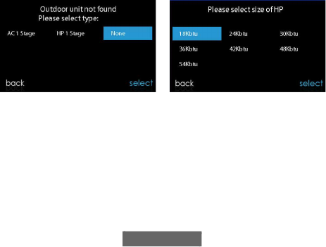
NOTE: If the outdoor unit cannot be found, the control will display
“Outdoor unit not found”.
• Select the appropriate unit installed; then, touch NEXT.
23
NOTE: For some communicating products (SPP and geothermal
package units), the selection screen may not be needed and may not
appear.
• The installer will first be instructed to select the appropriate size of the
outdoor unit; then, touch SELECT.
A13118
5.3. Indoor Evaporator Selection
If a furnace is installed with a variable capacity heat pump or an 18VS
heat pump or 19VS air conditioner, a screen will appear to select the
installed indoor evaporator coil. This selection is used to adequately
calculate the refrigerant charge required while in the heat pump charging
screens under Refrigerant Charging Greenspeed® Intelligence 18VS,
19VS Systems Section. Select “other” for non-Carrier evaporators.
AC1Stage — 1-stage air conditioner
*
AC2Stage —
*. Network Interference Module (NIM) may be required for these
selections to be displayed.
2-stage air conditioner
*
HP1Stage —
1-stage heat pump
*
HP2Stage —
2-stage heat pump
None — No outdoor unit installed

24
5.4. Electric Heater Selection
If the indoor equipment is a fan coil, the control will display “Searching
for heater” until one is found. If the electric heater is not self-identifying,
the select heater screen will appear. Touch the appropriate heater size;
then, touch SELECT.
A13119
5.4.1. Hydronic Heat Application
The Infinity System Control supports two types of Hydronic Heat
applications:
1. Hot water coil in combination with an FE fan coil and heat pump,
or hot water coil as sole heat source with an FE fan coil.
2. Non-zoned FE fan coil combined with radiant hot water heat.
In either application, a Hydronic Heat kit should be installed in place of
an electric heater. See FE fan coil Product Data for accessory part
number. The system will self-identify that hydronic heat has been
installed during electric heater selection. The system will treat the hot
water coil as either auxiliary heat in a heat pump application, or the sole
heat source. Setup options for Hydronic Heat applications are described
in the setup section of this instruction.
NOTE: The daily airflow verification test will take place even when the
radiant hydronic heat option is selected.

25
5.5. Searching for SAM Module (If Applicable)
“Searching for SAM Module” will appear on the screen to determine if a
System Access Module, used for home automation only, is connected to
the system.
The SYSTXCCSAM01 is not compatible with this control. The
compatible modules are SYSTXNNRCT01. The SAM is used for home
automation purposes and is NOT used to connect the system control to
the Internet. The Infinity System Control must have at least Version 8
software or newer to be compatible with the SAM.
NOTE: For more information regarding the SAM Module, reference the
latest version of the application specification entitled “SAM Remote
Access Application Specification, ASCII Protocol Information”,
available on HVACpartners.com, or the System Access Module
Installation Instructions.
A13117
5.6. Searching for Zones (If Applicable)
“Zoning - Searching” will appear on the screen to determine if any zones
are present. The screen will show Zone 1, Zone 2, etc. and indicate all
zones having either a Remote Room Sensor, or smart sensors associated
with them. If the system contains smart sensors, they must be assigned a
zone number before continuing. See the Smart Sensor Installation

26
Instructions on how to assign Smart Sensors to their respective zones.
After each zone has been identified, touch NEXT.
A12185
5.7. Filter Type Selection
The installer will next be prompted to select the air filter type installed
with the Infinity System. After the selection is made, touch NEXT.
• Air Filter: 1-in. to 4-in. media filter
• EAC: high voltage electronic air cleaner
• Air Purifier: Infinity® Series or Performance™ Series Air Purifier
5.8. Humidifier Installation
Next, the installer will be prompted to select whether a humidifier is
installed in the system. Select YES or NO, then touch NEXT.
5.9. Ultraviolet Lights Installation
Next, the installer will be prompted to select whether ultraviolet lights
are installed in the system. Select YES or NO, then touch NEXT.
5.10. Equipment Summary
The equipment summary screen will appear after accessories have been
selected. This screen will give a summary of all equipment automatically
found or manually selected. If an incorrect selection was made, touch

27
RE-INSTALL to restart the installation process. See the Infinity System
HVAC equipment Installation Instructions for more details, as provided.
A13120
5.11. Airflow Verification Check
The airflow verification check screen will appear next, as the system
performs this operation. This process will take about 1-1/2 minutes to
complete. When completed, a screen will appear displaying the results of
the check.
If the system has an indoor unit equipped with a previous-version
CFM-controlled blower system the screen will display the static pressure
(in inches of water) across the equipment at the expected highest
delivered airflow. If the blower RPM is greater than 1200, a warning will
appear, but equipment operation and the TrueSense™ dirty filter
detection operation will not be affected. Press NEXT when the airflow
verification check is complete.
If the system has an indoor unit equipped with an updated-version
CFM-controlled blower system (typically found in equipment
manufactured after November 2017), the screen will display the static
pressure (in inches) across the equipment at a pre-determined target
airflow CFM. If the achieved (actual) CFM is unacceptably below the
target CFM, a yellow notice will appear to invite the user to see the
Example: SPP Equipment Summary Screen

28
associated information screen; equipment operation and the TrueSense™
dirty filter detection operation will not be affected. Press NEXT when the
airflow verification check is complete.
NOTE: The airflow verification check occurs at initial installation, or
when FULL INSTALLATION or AIRFLOW VERIFICATION
TEST are selected in the INSTALLATION & SERVICE menu.
5.12. Duct Assessment (zoned systems only)
The duct assessment screen will be displayed next for zoned systems.
Touch NEXT to start Duct Assessment. Duct Assessment will measure
the relative size of the ductwork, up to and through the dampers. These
measurements are used to control the correct amount of airflow in the
zoned system. Status messages will appear on the screen to indicate what
the system is doing. The process will take approximately two minutes per
zone. The duct assessment will override a call for heat or cool.
A duct assessment will automatically occur each day at a user selectable
time. The factory default time is 1:00 p.m. local time but, may be
changed by entering the Zoning Setup menu. If there is an active call for
heating or cooling, the system will wait until the call is satisfied before it
performs the duct assessment. The system will first open all zones and
drive the blower to 175 CFM/ton of cooling (or the minimum indoor
unit’s airflow, whichever is greater). It will then take a static pressure
measurement. The system will then close all zones and open one zone at
a time, taking a static pressure measurement for each zone.
The system will then close all zones and take a pressure measurement,
getting a value for the duct leakage up to and through the dampers. With
these static pressure measurements, the system will calculate the relative
size of each zone as well as the percent leakage through the dampers at
the end of the process, the display will show the relative size of each zone
duct.

29
If the Infinity System Control detects an error (damper not moving or
damper wired backwards), it will perform the duct assessment again. If it
still detects a damper problem, it will default the measurements into
equal sizes, with 10% leakage, and display the zone number for the
suspected zone damper.
NOTE: The daily duct assessment will occur even if static pressure
monitoring is disabled. This is done to ensure that the system will
continue to provide proper airflow for all installed equipment, since duct
system changes may occur at any time, such as opened or closed
registers.
After the duct assessment is complete, touch NEXT.
6. Service Menu
The Service menus contain a set of vital information. This information
enables the installer or service person to view a summary of what has
been installed, etc. This information is not covered in the Owner’s
Manual.
To enter service menus, touch menu, then touch and hold the SERVICE
icon, for at least ten seconds, until the icon turns green. The following
screens are available in installation and service. To return to the previous
screen, touch BACK. To exit the Service menus, touch DONE.
NOTE: See the Owner’s Manual for information regarding software
upgrades.
NOTE: The user “selection of temperature units” affects the user screens
only. The service screens use degree F only. The user “selection of
temperature units” is under the display icon on the main menu.

30
A170181C
6.1. Equipment Summary
Touch EQUIPMENT SUMMARY to show indoor unit type and model
number, outdoor unit type (and model number if a 2-stage unit), filter
type, any accessories that are installed, and the number of zones in the
system. To return to the previous screen, touch BACK. To exit the
Service menus, touch DONE.
6.2. Installation
Touch INSTALLATION to perform the start-up process in order to learn
all equipment in system. Select FULL INSTALLATION, then touch
NEXT to initiate the process.
Touch Airflow Verification Test to perform a duct assessment. This can
be done if duct modifications have been made since installation of the
31
Infinity System Control. Duct assessment can be performed without
performing a full system install.
NOTE: For Small Packaged Products (SPP), please use the following
instructions for Set-up (Set-Up Section), Checkout (Checkout Section),
and Service (Service Information Section):
– For PAC AC Indoor and OAC HP Indoor, follow Fan Coil
instructions.
– For Gas PAC Indoor and Gas PHP Indoor, follow Furnace
instructions.
– For all PAC Outdoor, follow AC/Heat Pump instructions.
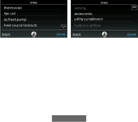
6.3. Set up
A13130
NOTE: Depending upon the equipment installed, the following options
will be displayed. See the Infinity System HVAC equipment Installation
Instructions for more details, as provided.
• Indoor:
– Furnace
– Fan coil
– PAC AC Indoor
– PAC HP Indoor
– GAS PAC Indoor
– GAS PHP Indoor

32
• Outdoor:
– AC/Heat pump
• Geo HP
• PAC AC outdoor
• PAC HP outdoor
• GAS PAC outdoor
• GAS PHP outdoor
Once the equipment has been selected, the appropriate menus will be
displayed.
6.3.1. Thermostat
First touch SETUP, then touch THERMOSTAT to set up the parameters
for the Infinity System Control.
6.3.1.1. Auto Mode Set Up
Once the auto changeover option has been selected, touch SAVE.
• Enable or Disable: Choose to enable or disable auto changeover
mode. Default = Enable
• Simultaneous Heat/Cool: Choose to turn simultaneous heat cool
demand feature on or off. Default = Off
• If Simultaneous Heat/Cool is turned ON, Auto changeover time is
grayed out and shows N/A.
• If Simultaneous Heat/Cool is turned OFF, Auto changeover time:
Adjustable from 5 to 120 minutes. Default = 30 minutes
NOTE: AUTO mode is intended to switch between Heating and Cooling
modes based on temperature demand. A gradual auto transition is the
energy-conscious default that will satisfy the majority of customers.
Some customers might have significant and simultaneous heating and
cooling demands in different zones. To address this need, a special
simultaneous heating and cooling demand auto mode could be enabled
by the Installer. The simultaneous heating and cooling demand auto

33
mode will result in higher energy usage but benefit the customer with
greater comfort.
A160183_2
6.3.1.2. Heat/Cool Deadband
The minimum difference enforced between heating and cooling desired
temperatures. The deadband does not change when the user changes
between Fahrenheit (°F) and Celsius (°C). Ex: A 2° deadband will be 2°F
or 2°C and does not change with units, °F and °C. This can allow one
setting to “push” the other to maintain this difference. When the correct
deadband is set, touch SAVE.
• Deadband: Adjustable from 0 to 6°. Default = 2°
6.3.1.3. Offsets
This option allows calibration (or deliberate miscalibration) of the
temperature and humidity sensors. These offsets are added to the actual
temperature/humidity values. See also Zone Offsets Section. When the
correct offsets are made, touch SAVE. If the system is non-zoned, the
indoor temperature offset is found on this screen. If the system is zoned,
the indoor temperature offset is found in the Zoning, Offsets screen.
• Outdoor temperature: Adjustable from -5 to 5°F (-3 to 3°C).
Default = 0°F
• Indoor temperature: Adjustable from -5 to 5°F (-3 to 3°C).
Default = 0°F

34
• Humidity: Adjustable from -10 – 10%. Default = 0%
NOTE: For single-zone systems, the indoor temperature offset is on this
screen. For zoning systems, there is a separate zone indoor temperature
offset screen in the zoning menu.
A190275
6.3.1.4. Reset Factory Defaults
This option allows the installer to reset certain factory parameters. After
the selections are made, touch SAVE.
• Program Schedule: Reset back to pre-programmed time and
temperature.
• User Settings: Reset user settings back to pre-programmed values.
• Install Settings: Reset installation settings back to pre-programmed
values.
• Last 10 Events: Reset the last 10 system events under the Service
menu.
A190397
6LQJOH]RQH6\VWHPV =RQLQJ6\VWHPV =RQLQJ6\VWHPV

35
6.3.1.5. Scheduling On/Off
This option lets the installer allow comfort schedule programming
features. After the selection is made, touch SAVE.
• Scheduling: On or Off. Default = On
6.3.1.6. Smart Recovery On/Off
NOTE: ”Smart Recovery” refers to transitions between and among the
Home, Sleep and Wake modes. Moving from the Away mode to any
other mode is covered by the “Advanced Smart Setback” feature.
Smart Recovery applies to programmable operation only. Smart
Recovery causes the system to ramp the system target setpoints to those
for the next programmed schedule period to help save energy during
period transitions. Smart Recovery will start recovery 90 minutes prior to
schedule change in both heating and cooling mode. After the selection is
made, touch SAVE.
• Smart Recovery: On or Off. Default = On
NOTE: The “Temperature Units Display” set-up section has been moved
to the Homeowner Screens. See the Owner’s Manual for more
information.
6.3.2. Fan Coil
First touch SETUP, then touch FAN COIL to set up the parameters for
the fan coil unit.
6.3.2.1. Airflow
This option allows the installer to select the appropriate air flow based on
the needs of the installation. The QUIET airflow means the minimum
cooling airflow that the system can safely run (typically 300 CFM/ton).
Use this setting if duct noise is a severe problem. Note that duct sweating
in high humidity environments could become an issue at low airflows.
The COMFORT airflow means airflow is varied depending on humidity

36
and temperature demand settings. This selection enables the full
dehumidify and comfort capabilities of the system. The EFF325 airflow
is a fixed airflow used to achieve specified ratings – no dehumidification
airflow reduction is performed. This is nominally 325 CFM/ton, but will
vary if a 2-stage outdoor unit is used. The EFF350 airflow is a fixed
airflow used to achieve specified ratings – no dehumidification airflow
reduction is performed. This is nominally 350 CFM/ton, but will vary if a
2-stage outdoor unit is used. The MAX airflow is a fixed 400 CFM/ton.
No dehumidification airflow reduction is performed.
NOTE: For Geothermal Heat Pumps, the airflow labels have been
changed from EFF325 and EFF350 to EFF1 and EFF2, respectively.
Nominal geothermal system airflows for these settings tend to be
different than the typical 325 and 350 CFM/ton values.
The dehumidify airflow, when set to NORMAL, is allowed to adjust to a
minimum to satisfy the dehumidification call. When set to HIGH, the
minimum airflow during the dehumidify mode is increased to reduce
duct and register sweating. Also the airflow increases minimum airflow
during normal cooling operation to help reduce duct sweating.
After the selections are made, touch SAVE.
• Cooling Airflow: Quiet, Comfort, EFF325 (or EFF1), EFF350 (or
EFF2), or Max. Default = Comfort
• Heating Airflow: Comfort, EFF325 (or EFF1), EFF350 (or EFF2), or
Max. Default = Comfort
• Dehumidify Airflow: Normal or High. Default = Normal
6.3.2.2. Altitude
• Static Pressure selection: 0 to 10,000 ft. This is used to correct the
static pressure readings the system performs.

37
6.3.2.3. Dehumidification Options
The Dehum Drain Time (Smart Evap™ feature) option turns off the
continuous fan at the end of cooling for fifteen minutes in order to drain
the indoor coil of water. The fan will only be turned off if a dehumidify
demand existed at the start of or during the cooling cycle.
The Electric Reheat option (fan coils, only) enables the electric heat to be
used while cool-to-dehumidify is running. This will allow the
cool-to-dehumidify function to run longer, greatly improving humidity
control in cooling mode. Accumulated electrical energy used while
reheating (in kilowatt-hours) is shown on the Fan Coil Run Hours screen
and can be reset there. This option is only available with fan coil systems.
Self-identifying (staging) heaters provide the best performance for
re-heat dehumidification. For reheat applications, 9kW heaters provide
the best performance. The reheat algorithm functions along with the
overcool algorithm. If the room temperature is low enough that
overcooling is not allowed, reheat will not be allowed. Overcooling must
happen before the electric heaters are energized.
After the selections are made, touch SAVE.
• Dehum Drain Time: Adjustable from 5 to 60 minutes or OFF. Default
= 15 minutes
• Electric Reheat: Yes or No. Default = No
6.3.2.4. Fan Coil G-Terminal Input
This setup option selects desired operation when the R to G contact is
closed on the fan coil control board. Under this function option, fan turns
on fan to selected fan speed when G terminal is energized. Use the alert
function to select the contact state for an alert. Select Normally Open or
Normally Closed, and then save your selection. Shutdown shuts off fan
and equipment when initiated. After the selections are made, touch Save.
• Shutdown:
– Normally Open

38
– Normally Closed
– The shutdown function may not be immediate. Blower off delays,
etc., will still be used. The shutdown is not intended for commercial
applications. If immediate shutdown is required, provision must be
made to remove power to indoor unit.
A13229
6.3.2.5. Fan Coil G-Terminal Alert
Use the alert function to select the contact state for an alert. Select
Normally Open or Normally Closed, and then save your selection.
A13230
Shutdown: This setup option selects the change of state required for
shutdown. Select Normally Open or Normally Closed, and then save
your selection.

39
6.3.2.6. Fan Coil G Terminal Alert Label
Once the G Terminal Alert label has been entered, it is shown both on the
main screen and in the notification email when the alert becomes active.
A14224
6.3.3. Furnace
First touch SETUP, then touch FURNACE to set up the parameters for
the furnace unit.
A14225A_2
6.3.3.1. Furnace Airflow
Selects the airflow of the furnace when heating. EFFICIENCY is the
airflow used to meet specified ratings, COMFORT is a decreased
airflow used to increase the output air temperature and provide increased
comfort.
For the Low heat rise option, set to ON if the system contains a bypass
humidifier. The ON setting will increase the furnace low heat airflow.
After the selections are made, touch SAVE.

40
• Furnace Air Flow: Comfort or Efficiency. Default = Comfort
• Low Heat Rise: On or Off. Default = Off
6.3.3.2. AC/HP Airflow
NOTE: For Geothermal Heat Pumps, this option will be shown as ’Geo
HP’ airflow. This option elects the airflow of the furnace when cooling,
heat pump heating, and dehumidification when used with a geothermal
heat pump.
The QUIET airflow means the minimum cooling airflow that the system
can safely run (typically 300 CFM/ton). Use this setting if duct noise is a
severe problem.
NOTE: Duct sweating in high humidity environments could become an
issue at low airflows.
The COMFORT airflow means airflow is varied depending on humidity
and temperature demand settings. This selection enables the full
dehumidify and comfort capabilities of the system. The EFF325 (or
EFF1) airflow is a fixed airflow used to achieve specified ratings – no
dehumidification airflow reduction is performed. This is nominally 325
CFM/ton, but will vary if a 2-stage outdoor unit is used. The EFF350 (or
EFF2 airflow is a fixed airflow used to achieve specified ratings – no
dehumidification airflow reduction is performed. This is nominally 350
CFM/ton, but will vary if a 2-stage outdoor unit is used. The MAX
airflow is a fixed 400 CFM/ton. No dehumidification airflow reduction is
performed.
NOTE: For Geothermal Heat Pumps, the airflow labels have been
changed from EFF325 and EFF350 to EFF1 and EFF2, respectively.
Nominal geothermal system airflows for these settings tend to be
different than the typical 325 and 350 CFM/ton values.
The dehumidify airflow, when set to NORMAL, the airflow is allowed
to adjust to a minimum to satisfy the dehumidification call. When set to

41
HIGH, the minimum airflow during the dehumidify mode is increased to
reduce duct and register sweating. Also the airflow increases minimum
airflow during normal cooling operation to help reduce duct sweating.
After the selections are made, touch SAVE.
• Cool: Quiet, Comfort, EFF325 (or EFF1), EFF350 (or EFF2), or Max.
Default = Comfort
• HP Heat: Comfort, EFF325 (or EFF1), EFF350 (or EFF2), or Max.
Default = Comfort
• Dehumidify: Normal or High. Default = Normal
6.3.3.3. Furnace Staging
This option controls the staging of the furnace and selects the minimum
amount of time low stage must operate before high stage is activated.
SYSTEM setting will allow the Infinity Zone Control to determine
furnace staging. LOW will only run the low stage of furnace heat.
LOW-MED will run the low and medium stages (2 stages of heat). MED
will only run the medium stage of heat. MED-HIGH will run the
medium and high stages (2 stages of heat). HIGH will only run the high
stage of furnace heat.
NOTE: Two-stage furnace has LOW and HIGH selections only.
• Stages: System, Low, Low-Med, Med, Med-High, or High. Default =
System
6.3.3.4. Furnace Airflow Limits (modulating furnace
only)
The following settings allow the installer to restrict the furnace within
certain minimum and maximum airflows. These airflows are converted
to capacities. The Min and Max limits are determined by the equipment
size. These settings are not the same as the zoning airflow limits.

42
• Min. modulating limits: Minimum CFM to run a modulating furnace.
This will increase the minimum operating capacity of the furnace.
Default value is the furnace air flow for the lowest heat capacity.
• Max. modulating limits: Maximum CFM to run a modulating
furnace. This will increase the maximum operating capacity of the
furnace. Default value is the furnace air flow for the highest heat
capacity
6.3.3.5. Furnace Off Delay
This option denotes the amount of time the blower will continue to run
after heating has shut off. After the selection is made, touch SAVE.
• Furnace Off Delay: 90, 120, 150 or 180 seconds. Default = 120
seconds
6.3.3.6. Altitude
For gas de-rating, this setting will adjust the furnace’s airflow to
compensate for altitude. Altitude adjustment is not available with older
furnaces. Please see furnace instructions for further details. After the
selection is made, touch SAVE.
• Altitude: 0000 – 2000, US 2001 – 3000, CN 2100 – 4500, US 3001 –
4000, US 4001 – 5000, US 5001 6000, US 6001 – 7000, US 7001 –
8000, US 8001 – 9000, and US > 9000. Default = US 2001-3000
• Static Pressure selection: 0 to 10,000 ft. This value is used to correct
the static pressure readings the system performs.
6.3.3.7. Furnace Dehumidifier Drain
This option selects the time the continuous fan turns off at the end of
cooling in order to drain the indoor coil of water (Smart Evapt feature).
The fan will only be turned off if a dehumidify demand existed at the
start of or during the cooling cycle.
• Dehumidify Drain Time: Adjustable from 5 to 60 minutes. Default =
15 minutes

43
6.3.3.8. Furnace G Terminal
This setup option selects desired operation when the R-G circuit changes
state on the furnace control board depending on setup.
Under the function option, FAN turns on fan to selected fan speed when
G terminal is energized. SHUTDOWN shuts off fan and equipment
when initiated.
After the selections are made, touch SAVE.
• Function: Disabled, Fan or Shutdown. Default = Disabled
• Fan Speed: Low, Med, or High. Default = Low
• Shutdown:
– Normally Open
– Normally Closed
– The shutdown function may not be immediate. Blower off delays,
etc., will still be used. The shutdown is not intended for commercial
applications. If immediate shutdown is required, provision must be
made to remove power to indoor unit.
6.3.3.9. Furnace G-Terminal Alert
Use the alert function to select the contact state for an alert. Select
Normally Open or Normally Closed, and then save your selection.
A13230

44
Shutdown: This setup option selects the change of state required for
shutdown. Select Normally Open or Normally Closed, and then save
your selection.
6.3.3.10. Furnace G Terminal Alert Label
Once the G Terminal Alert label has been entered, it is shown both on the
main screen and in the notification email when the alert becomes active.
A170248
6.3.4. AC/Heat Pump
First touch SETUP, then touch AC/HEAT PUMP to set up the
parameters for the AC/Heat Pump unit.
A14227A_2
6.3.4.1. Latching
High Cool Latch

45
A13227A
• System in Control: The system will decide which stage should be
running to satisfy the cooling demand.
• High Cool: Temperature above which only the high stage of cooling
will be energized.
• Only Low Cool: The system will only run in low stage cooling.
High Heat Latch
A13228
• System in Control: The system will decide which stage should be
running to satisfy the heating demand.
• High Heat: Temperature below which only the high stage of heating
will be energized.
• Only Low Heat: The system will only run in low stage heating.
6.3.4.2. Cooling Lockout
Outside temperature below which cooling will not be provided. After the
selection is made, touch SAVE.

46
• Cooling Lockout Temp: None, 45, 50 or 55 (°F). Default = None
NOTE: When simultaneous heating and cooling demand feature is on,
the cooling lockout shall be ignored.
6.3.4.3. Defrost Interval
Time interval at which defrost cycles can occur on a heat pump. AUTO
means the defrost interval is optimized by the outdoor control. After the
selection is made, touch SAVE.
• Set Defrost Interval: 30, 60, 90, 120 minutes or AUTO. Default =
AUTO
NOTE: See Heat Pump Installation Instructions for Defrost Timing
Interval when using AUTO Defrost.
6.3.4.4. Low Ambient Cooling
Selecting YES will enable the low ambient cooling operation in the
outdoor unit. This setting is only available with compatible
communicating outdoor units and with Cooling Lockout set to NONE.
Low ambient kits are not needed with many communicating outdoor
units. Refer to the outdoor unit Product Data or Installation Instructions
for more information. After the selection is made, touch SAVE.
• Low Ambient Cooling: Yes or No. Default = No
6.3.4.5. Quiet Shift
This option turns on Quiet Shift function in 1-stage or 2-stage
communicating heat pumps. After the selection is made, touch SAVE.
NOTE: This option is not available with variable speed heat pumps nor
geothermal units.
• Quiet Shift: On or Off. Default = Off
6.3.4.6. AC/Heat Pump RPM Max
Used with variable capacity heat pumps, this option clamps the
operating speed of the heat pump to this maximum. Used to reduce

47
operating noise while in high heating capacity. Reducing this value will
reduce the heating capacity of the heat pump. After the selection is made,
touch SAVE.
• AC Heat Pump Max RPM: Adjustable from 4500 – 7000. Default =
7000 RPM
6.3.4.7. Defrost Fan Delay
Turns on the outdoor unit fan at the end of a defrost cycle for
approximately 12 seconds. This helps to reduce any nuisance refrigerant
noise caused by the switching reversing valve. This setup is only
available on communicating heat pumps. After the selection is made,
touch SAVE.
• Defrost Fan Delay: Yes or No. Default = No
6.3.4.8. Brownout Disable
This option turns off the high voltage brownout detection function in the
outdoor unit control. After the selection is made, touch SAVE.
• Brownout Disable: On or Off. Default = Off
6.3.4.9. Low Air Multiplier
Adjusts the airflow speed on non-communicating two-stage units.
Choose 0.65 for units with a Bristol compressor, choose 0.80 (default) for
units with a Copeland scroll compressor.
6.3.4.10. Energy Efficiency
This option is used to input the published ratings of the installed air
conditioner or heat pump as part of the energy tracking calculation. After
the ratings are entered, touch SAVE.
6.3.5. Heat Source Lockout
First touch SETUP, then touch HEAT SOURCE LOCKOUTS to set up
the parameters for the AC/Heat Pump unit.

48
For hydronic heat applications, this option allows the installer to set the
lockout temperatures below which only the hydronic coil will operate,
and the lockout temperature above which the hydronic coil will not
operate. After the selections are made, touch SAVE.
A12149
• HP Lockout: Adjustable from -20 to 55°F (-28 to 13°C) or None.
Default = None
• Furnace, Electric Heat or Hydronic Lockout: Adjustable from 15 to
55°F (-9 to 13°C) or None. Default = None
• Defrost with Furnace, Electric Heat or Hydronic: Yes or No.
Default = Yes
– For Geothermal units, lockout for auxiliary heat (furnace or electric
resistance) is not enabled.
NOTE: When simultaneous heating and cooling demand feature is ON,
the system will try to respect the settings for heat source but may override
the settings if the preferred heat source is unable to deliver heat.
6.3.6. Stages / Latch for 18VS
For 18VS heat pumps, the cooling and heating stage/latch can be
changed. Select cooling or heating next to stages/latch. The maximum
stage and the minimum stage can be selected. The minimum selected
stage can be locked-in or set based upon the outside temperature.

49
A14228A
6.3.7. Geothermal HP (when available)
First touch SETUP, then touch Geo HP to set up the parameters for the
Geo HP unit.
A160188C
6.3.7.1. Freeze Limits
This setting controls the temperature level to which the loop liquid can
drop before the Geo HP unit will stop operating. See the Geo HP
Installation Instructions for more details. Typically, 26°F is chosen for

50
open-loop systems using untreated water; and 15°F is chosen for
closed-loop systems using glycol or other anti-freeze solutions. After the
selection is made, touch SAVE.
• Freeze Limits: 26°F or 15°F. Default = 26°F
A150179
6.3.7.2. Lockout Count
This setting controls the number of times within an hour that the HPS or
LPS trips before the Geo HP compressor will lockout for four hours.
After the selection is made, touch SAVE.
• Lockout Count: 4 or 2
• Default = 2
A150180

51
6.3.7.3. Brownout Override
This option controls the low voltage brownout override function in the
Geo HP unit. After the selection is made, touch SAVE.
• Brownout Override: Active or Inactive. Default = Inactive
A150181
6.3.7.4. Geothermal HP Energy Tracking
Energy tracking for geothermal heat pumps requires the installation of an
Entering Water Temperature (EWT) sensor. See the geothermal heat
pump literature for information on installing this sensor.
If the EWT sensor is installed, the installer will be able to enter the Loop
Flow Rate and the Loop Pump power. See the figure in the Geothermal
HP Section. These inputs will help the Energy Tracking algorithm
properly calculate geothermal heat pump usage. See the geothermal heat
pump literature for details.
If the EWT error message is shown, as illustrated in the Geothermal HP
Section, that means that the EWT sensor was installed and had valid
readings at one time, but is now malfunctioning. See the geothermal heat
pump literature for details.
6.3.8. Zoning (If Applicable)
First touch SETUP, then touch ZONING to set up the parameters for the
zoning system (if applicable).

52
A12191
6.3.8.1. Disable Zoning
This option allows the installer to enable or disable zoning. After the
selection is made, touch SAVE.
• Disable Zoning: Yes or No. Default = No
6.3.8.2. Zone Offsets
This option allows actual temperature offset for each zone, allowing
calibration (or deliberate miscalibration) of each sensor. Use the Left (<)
or Right (>) buttons to change the zone. After the selection is made,
touch SAVE.
• Temperature Offset: Adjustable between -5 to 5°F (-3 to 3°C).
Default = 0°F
6.3.8.3. Airflow Limits
Since a bypass damper is prohibited in this system, this setting is used to
select the maximum allowable noise/airflow relationship into each zone
based on air noise and comfort requirements. LOW means 100% of
maximum assessed airflow; MED-LOW means 138% of maximum
assessed airflow; MEDIUM means 176% of maximum assessed airflow;
MED-HIGH means 214% of maximum assessed airflow; HIGH means
250% of maximum assessed airflow; and NO LIMIT means the

53
equipment does not stage down due to airflow, but the system may stage
down due to high static pressure.
CFM associated for each limit is shown on the screen. Compare this
value with the equipment’s low stage CFM value to ensure that
equipment will run for each zone. Assessed airflow is determined as
described in DUCT ASSESSMENT.
After the selections are made, touch SAVE.
• Touch the zone name that you wish to change
• Select the zone to adjust airflow: Low, Med-Low, Medium,
Med-High, High, or No Limit. Default = High
6.3.8.4. Duct Assessment Time
NOTE: The daily duct assessment will occur even if static pressure
monitoring is disabled. This is done to ensure that the system will
continue to provide proper airflow for all installed equipment, since duct
system changes may occur at any time, such as opened or closed
registers.
This option allows the installer to select the time in which the duct
assessment will be performed. After the selection is made, touch SAVE.
• Duct Assessment Time: Selectable between 12 AM and 11PM.
Default = 1 PM
6.3.9. Accessories
First touch SETUP, then touch ACCESSORIES to set up the parameters
for the accessories installed with the system.
6.3.9.1. Filter
NOTE: The daily duct assessment will occur even if static pressure
monitoring is disabled. This is done to ensure that the system will
continue to provide proper airflow for all installed equipment, since duct

54
system changes may occur at any time, such as opened or closed
registers.
With this option, the installer has the option of selecting pressure
monitoring, the type of filter installed, and the time interval for cleaning.
After the selections are made, touch SAVE.
• Pressure Monitoring (not available or effective with air cleaners that
do not use filter media, such as Electric Air Cleaners): Enable or
Disable. Default = Enable
• Clean Interval: Selectable from 1 to 18 months. Default = 3 months
• Filter Type: Air Filter, Electric Air Cleaner or Air Purifier. Filter type
is selected during installation; otherwise default = air filter
6.3.9.2. Humidifier
With this option, the installer has the option of selecting whether a
humidifier is installed, to humidify with the fan in low speed, and the
time interval for changing the humidifier pad. After the selections are
made, touch SAVE.
• Humidifier Installed: Yes or No. Humidifier selection made during
installation; otherwise default = No
• Change Pad: Selectable from 1 to 24 months. Default = 12 months
• Humidify with Fan: Yes or No. Default = No
6.3.9.3. Ultraviolet Lights
With this option, the installer has the option of selecting whether
ultraviolet lights are installed, and the time interval for changing the
ultraviolet lights. After the selections are made, touch SAVE.
• UV Lights Installed: Yes or No. UV Lights selection made during
installation; otherwise default = No
• Change Interval: Selectable from 1 to 48 months. Default = 12
months

55
6.3.9.4. Ventilator
When a ventilator is installed, the installer has the option of selecting the
time interval for cleaning the ventilator. After the selections are made,
touch SAVE.
• Clean Interval: Selectable from 60, 90, 120, 150 or 180 days. Default
= 90 days
NOTE: This option may NOT be available with the ERVXXNVA
ventilator due to its simplified control design.
6.3.10. Utility Curtailment
NOTE: Utility Curtailment and Utility Saver functions are different than
the Utility Demand Response function described in the Owner’s Manual.
Utility Curtailment/Utility Saver uses the UTIL and Y2 (or equivalent)
terminals on the Infinity System compressor section control board to
receive a dry contact relay signal from the Utility, typically from the
electric meter assembly, to signal a curtailment period. This section
describes the actions taken in response to that signal. See the equipment
installation instructions for more information on wiring the compressor
section control board to the Utility connections.
Utility Saver is used to force the equipment to a lower stage (low or off)
when activated by the utility company, typically during peak load times.
This setup is available only if the equipment has a utility saver input
(refer to outdoor equipment installation instructions). This setup controls
the response of the equipment when the utility saver input is active.
DISABLED means that the curtailment function is not active. TURN
OFF means the outdoor unit is to be turned off when the curtailment
function is active. LOW STAGE means the outdoor unit will run in lows
stage when the curtailment function is active. After the selections are
made, touch SAVE.

56
A12193
• Cooling: Disabled, Low Stage or Turn off. Default = Disabled
• Heat Pump: Disabled, Low Stage or Turn off. Default = Disabled
6.3.11. Hydronic Airflow
NOTE: The daily duct assessment will occur even if Hydronic Airflow is
set to Off. This is done to ensure that the system will continue to provide
proper airflow for all installed equipment, since duct system changes
may occur at any time, such as opened or closed registers.
This option allows the installer to select the airflow for the fan coil when
paired with a hydronic coil. After the selections are made, touch SAVE.
A12194

57
• Airflow: Selectable between Off to Max in 50 CFM increments.
Default = Off, 500 CFM, Max = (odu_size in KBTU * 400/12)
NOTE: Selected airflow used during hydronic heating is a fixed value, it
does not vary.
• Blower On Delay: Selectable from 0 to 240 seconds. Default = 30
seconds
• Blower Off Delay: Selectable from 0 to 240 seconds. Default = 0
seconds
6.4. Check out
Touch CHECKOUT to view the equipment installed in the system.
Perform checkout test to make sure each piece of equipment is operating
properly.
WARNING
!
PROPERTY DAMAGE AND/OR PERSONAL INJURY
HAZARD
Failure to follow this warning could result in property damage, personal
injury or death.
Before running Check Out mode, make sure that all HVAC equipment is
properly installed. See the equipment installation instructions for details
and additional safety information.

58
A13122A
6.4.1. Electric Heat
If you have a fan coil with electric heaters, this menu item will allow the
heaters to be exercised. With self-identifying electric heaters, three stages
of electric heat are available to be exercised in any combination.
Non-identifying heaters will only provide one stage of heat; or perhaps
may have fixed-timed staging. See the instructions provided with the
electric heat accessory. After the selections are made, touch START.
• Low Heat: Selectable from 0 to 120 minutes. Default = 5 minutes
• Medium Heat: Selectable from 0 to 120 minutes. Default = 5 minutes
• High Heat: Selectable from 0 to 120 minutes. Default = 5 minutes
6.4.2. Furnace
Make sure the furnace is properly installed.
This option allows the furnace to be exercised. First, a low heat run time
and high heat run time are selected. The furnace will execute its ignition
start-up sequence. This sequence will be displayed on the screen. After
the gas valve and blower motor turn on, the screen will show the current
operating status of the furnace. After the selections are made, touch
START.
• Low Heat: Selectable from 0 to 120 minutes. Default = 5 minutes
• High Heat: Selectable from 0 to 120 minutes. Default = 5 minutes

59
6.4.3. Hydronic
This option allows the hydronic heat relay to be exercised. First, it will
energize the relay and turns on the blower. This sequence will be
displayed on the screen. After the selections are made, touch START.
• Hydronic heater check: Selectable from 0 to 120 minutes. Default =
5 minutes
6.4.4. Air Conditioning
This option allows the air conditioner to be exercised. With a 2-stage AC
unit, a low cool and a high cool run time are independently selectable to
exercise. The display will change to show the AC operating status. After
the selections are made, touch START.
For 18VS heat pumps, you can select the stage at which the heat pump
will exercise. During the checkout, the stage and time can be changed by
pressing the Change button on the checkout status screen.
NOTE: Airflows during Checkout modes are fixed to the
EFFICIENCY setting and are independent of other airflow settings. To
view airflows for normal air conditioning cooling mode, exit the
CHECKOUT screen and apply a heating demand to the system.
• Low Cool Run Time: Selectable from 0 to 120 minutes. Default = 5
minutes
• High Cool Run Time: Selectable from 0 to 120 minutes. Default = 5
minutes
6.4.5. Heat Pump Heating
The heat pump heating mode can be exercised with this menu option.
With a 2-stage heat pump, a Low Heat and a High Heat Run Time are
independently selectable to exercise.
For variable speed heat pumps, you can select the speed at which the heat
pump will exercise.

60
For VS heat pumps, you can select the stage at which the heat pump will
exercise. During the checkout, the stage and time can be changed by
pressing the Change button on the checkout status screen.
After the selections are made, touch START.
NOTE: Airflows during Checkout modes are fixed to the EFFICIENCY
setting and are independent of other airflow settings. To view airflows for
normal air conditioning cooling mode, exit the CHECKOUT screen and
apply a heating demand to the system.
• Low Heat Run Time: Selectable from 0 to 120 minutes. Default = 5
minutes
• High Heat Run Time: Selectable from 0 to 120 minutes. Default = 5
minutes
• Speed (variable speed heat pump only): Selectable from lowest
available to 100%. Default = lowest available as specified by variable
speed heat pump
• Defrost: Yes or No. Default = No (For Geothermal Heat Pumps, this
option is not available.)
6.4.6. Heat Pump Cooling
The heat pump cooling mode can be exercised with this menu option.
With a 2-stage heat pump, a Low Cool Run Time and a High Cool Run
Time are independently selectable to exercise.
For variable speed heat pumps, you can select the speed at which the heat
pump will exercise.
For 18VS heat pumps, you can select the stage at which the heat pump
will exercise. During the checkout, the stage and time can be changed by
pressing the Change button on the checkout status screen.
After the selections are made, touch START.
NOTE: Airflows during Checkout modes are fixed to the
EFFICIENCY setting and are independent of other airflow settings. To

61
view airflows for normal air conditioning cooling mode, exit the
CHECKOUT screen and apply a heating demand to the system.
• Low Cool Run Time: Selectable from 0 to 120 minutes. Default = 5
minutes
• High Cool Run Time: Selectable from 0 to 120 minutes. Default = 5
minutes
• Speed (variable speed heat pump only): Selectable from lowest
available to 100%. Default = lowest available as specified by variable
speed heat pump
6.4.7. Humidifier
The humidifier can be exercised On and Off with this menu option. To
end the humidifier checkout, touch STOP.
• Humidifier Check: On or Off
6.4.8. Ventilator
The ventilator can be exercised through all of its operating speeds with
this menu option. To end the ventilator checkout, touch STOP.
• Ventilator Check: High, Low or Off
NOTE: This option may NOT be available with the ERVXXNVA
ventilator due to its simplified control design.
6.4.9. Zoning (If Applicable)
6.4.9.1. Airflow Limits
Because there is no bypass damper, the zone airflow limit check will
allow the installer to assess the airflow noise generated by the system
providing the maximum amount of airflow to each zone. Touch
AIRFLOW LIMITS: When START is touched, the selected zone’s
damper will fully open, all others will close, and the indoor unit will
provide the maximum airflow for that zone (as selected in SETUP —
ZONING, Airflow Limits). If the airflow noise is objectionable, the

62
installer can select a lower airflow noise limit. If the noise is not
objectionable, the installer should leave HIGH selected, or even NO
LIMIT.
NOTE: Selecting a lower airflow noise limit may decrease the
homeowner’s comfort in that zone.
Touch the Left (<) or Right (>) buttons to change the desired zones. Once
the proper airflow limits are set, touch SAVE, to see ZONING
CHECKOUT menu.
6.4.9.2. Damper/Sensor Check
The Sensor/Damper Check allows the installer to check each zone
damper for operation, as well as insure the zone sensor corresponds to
that particular zone. When first initiated, the Zone 1 damper will fully
open, and all other zones will close. Using the Left (<) or Right (>)
buttons, the installer can select each zone and verify the damper is fully
open while all other dampers remain closed.
After proper damper operation has been verified, the installer can now
check and verify that each Remote Room Sensor corresponds to the
proper zone damper in the same zone. For systems with remote room
sensor, temporarily disconnect any other zone Remote Room Sensor (at
sensor location). That zone damper will now open, while the Zone 1
damper will close.
For systems using Smart Sensors, the installer may press and hold the
Hold and Mode buttons simultaneously for 3 seconds to change the zone
under test. This should be done with each zone to verify that the zone
sensor corresponds to that particular zone.
Once each zone has been checked, touch DONE to return to the
ZONING CHECKOUT menu.

63
6.4.9.3. Zone Duct Assessment
This screen shows the results from the previous duct assessment. The
duct assessment is performed at initial start-up and at 1 P.M. or the
installer selected time each day. If another duct assessment is desired, the
service technician should perform a re-install of the system.
NOTE: A Duct Assessment will automatically occur every 24 hours at
selected time to check system static and calibrate dampers.
Once the duct assessment is complete, touch DONE to return to the
ZONING CHECKOUT menu.
6.4.9.4. Sensor Type
This option shows a list of all zones with corresponding sensor types.
6.5. Service Information
The Service Info menu will only show the equipment installed in the
system. To enter this menu of options, touch SERVICE
INFORMATION.
A13123A

64
6.5.1. Advanced Diagnostics
When viewing the Service Information screen, there is a button labeled
View Diagnostics, which provides the top 3 most likely root causes for
the most recent fault.
NOTE: This feature is only available with compatible models. See the
Infinity equipment product data or installation instructions for more
information.
6.5.2. Fan Coil Status
The fan coil status screen displays relevant information about the fan coil
operation. To return to the previous screen, touch BACK. To exit the
Service menus, touch DONE.
A12197
6.5.3. Furnace Status
The furnace status screen displays relevant information about the furnace
operation. To return to the previous screen, touch BACK. To exit the
Service menus, touch DONE.

65
A12198
6.5.4. AC Status
The AC status screen displays relevant information about the AC
operation. To return to the previous screen, touch BACK. To exit the
Service menus, touch DONE.
NOTE: Screen data will vary based on unit installed.
A12199
6.5.5. Heat Pump Status
The heat pump status screen displays relevant information about the heat
pump operation. To return to the previous screen, touch BACK. To exit
the Service menus, touch DONE.
NOTE: Screen data will vary based on unit installed.

66
A12200
6.5.6. Geothermal HP Status
The Geo HP status screen displays relevant information about the Geo
HP operation. To return to the previous screen, touch BACK. To exit the
Service menu, touch DONE.
NOTE: Screen data will vary based on unit installed.
A160192
6.5.7. Zoning Status
The zoning status screen displays relevant information about the zoning
operation. To return to the previous screen, touch BACK. To exit the
Service menus, touch DONE.

67
6.5.8. Last 10 System Events
This screen will show the last 10 events that occurred throughout the
system. Each entry has the time and date incident recorded. These events
are stored in the memory of the control and are resettable in the
THERMOSTAT SETUP screen under the RESET FACTORY
DEFAULT selection. Each entry shows the equipment that generated the
event. To return to the previous screen, touch BACK. To exit the Service
menus, touch DONE.
A12151
6.5.9. Run/Fault History
This information is stored in the equipment circuit boards (if
communicating) and displayed on the control. The indoor unit and
outdoor unit (if communicating) have the following histories. To return to
the previous screen, touch BACK. To exit the Service menus, touch
DONE.
• Resettable Faults: Fault counters for each piece of equipment that can
be reset.
• Cycle Counters: Number of heat/cool/power cycles the unit has
performed.
• Run Times: Lifetime hours of operation in heating, cooling, and how
long the unit has been powered.

68
6.5.10. Model/Serial Numbers
This menu item allows the installer to view the model number, serial
number (if available), and control software version (if available) of all
communicating pieces of equipment in the system, including the wall
control. This information resides in the original equipment circuit
board(s) from the factory. If an equipment circuit board has been
replaced, the model and serial number will no longer be displayed. To
return to the previous screen, touch BACK. To exit the Service menus,
touch DONE.
A14230
6.5.11. Service Phone Number
This menu item allows the installer to view the name and phone number
that the homeowner can call for future service of the system. This name
and phone number will appear to the homeowner whenever a service
reminder pop-up message is displayed (i.e. Change Filter, etc.). The
contact number can be changed under the dealer system menu. To return
to the previous screen, touch BACK. To exit, touch DONE.
6.5.12. Energy Tracking
NOTE: Energy Tracking is only available for applicable equipment. See
The Product Data for the equipment in question to see if Energy Tracking

69
is available for that device. Both indoor and outdoor units must have
energy tracking capability for this feature to function fully.
This menu item allows the installer to view the energy usage of each
piece of equipment connected to the system. To return to the previous
screen, touch BACK. To exit the Service menus, touch DONE.
A14231
6.6. Refrigerant Charging: Greenspeed®
Intelligence, 18VS™, 19VS™ Systems
For variable capacity and multi-stage heat pumps and AC units, a
refrigerant charging menu is available to aid in the proper charging of the
system. Enter the menu from the service screens by touching
REFRIGERANT CHARGING.
The option for HTG CHECK CHARGE is only available for heat pump
units, and not available in AC units.
NOTE: See the outdoor equipment Installation Instructions for
information on what conditions CHARGING COOLING and HTG
CHECK CHARGE are available.
6.6.1. Charging
Within the CHARGING COOLING or HTG CHECK screens, the
installer will have the ability to enter the LINESET length and the
VAPOR LINE diameter. After the selections are made, touch NEXT.

70
• Lineset: Selectable from 5 to 200 feet
NOTE: For 18/19 VS product, 100 feet is the maximum allowed
refrigerant line length.
• Vapor line: Selectable with various diameters by using the up and
down buttons
Next, the installer will enter the WEIGH IN screen to verify the current
total charge is accurate. Once the installer has confirmed, touch DONE.
Next, the installer will enter the SERVICE VALVE SUBCOOL screen.
This screen will show the current liquid line subcool target (in °F). To
begin the charging, touch START. If the outdoor temperatures are not in
the required range, Service Valve Subcool may not be available. For
HTG CHECK CHARGE, the option Service Valve Subcool is
unavailable.
Next, the installer will enter the SERVICE VALVE INFORMATION
screen. The current liquid line subcool target, stabilization time, mode
and speed in rpm, EXV position in percent, indoor airflow in CFM,
outdoor coil temperature in °F, indoor temperature in °F, outdoor
temperature in °F, compressor discharge pressure in psig, and
accumulator suction pressure in psig are displayed on this screen. Once
the stabilization time has expired, touch DONE.
NOTE: Screen data will vary based on unit installed.
A14286A_2

71
A14664a
6.6.2. Pump Down
Because this system has an inverter controlled compressor, suction
pressure transducer and EXV, conventional procedure cannot be used to
“pump down” and isolate the refrigerant into the outdoor unit. The
control has provisions to assist in performing this function.
• Select mode to pump down in (COOL or HEAT). COOL mode
allows refrigerant to be isolated in outdoor unit. HEAT mode allows
the refrigerant to be isolated in indoor coil and lineset. Set desired time
period. Default time period for procedure is 120 minutes.
• Touch START to begin the pump down process. Unit will begin
running in selected mode after a brief delay.
6.6.3. Evacuation
Because this system has an EXV for the heating expansion device,
additional steps must be taken to open the EXV if the heat pump unit
must be evacuated for service reasons. If the EXV is not open when
pulling a vacuum or recovering refrigerant from the heat pump unit,
extended evacuation time may be required and/or inadequate vacuum
obtained. The control has provisions to open the EXV for refrigerant
recovery and/or evacuation.
• Set desired time period. Default time period for procedure is 120
minutes.
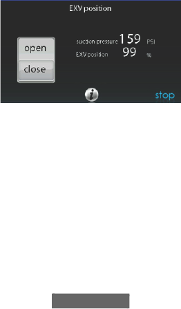
72
• Touch START on Infinity System Control or service tool to open the
valve.
• Begin evacuation or refrigerant recovery as required for the procedure
after control indicates the EXV is open. Power may be removed from
heat pump after the control indicates “READY TO EVACUATE.”
6.6.4. EXV Position
This screen allows the installer to set the EXV position and monitor the
suction pressure.
NOTE: Screen data will vary based on unit installed.
A14233
6.7. Dealer Logo for Series B
NOTE: More detailed information can be found on HVACPartners.com
under: Products and Dashboards > Product Catalog > Residential
Controls < Systems Controls > SYSTXCCITC01-C > Documents >
Marketing > Miscellaneous > Infinity SystemControl Dealer Logo
Application - Instructions.
Touch DEALER LOGO to upload the dealer logo and contact
information from a micro SD card connected to the Infinity System
Control. The “Dealer Logo Application” PC/MAC Desktop application
download available at www.MyInfinityTouch.Carrier.com is required to

73
properly format the dealer logo and contact information for use on the
wall control.
Along with the dealer logo (if any), three lines of dealer information are
provided on the wall control:
Dealer name (50 characters, max)
Dealer phone number (20 characters, max)
Dealer URL (50 characters, max)
The wall control dealer information display is 30 characters wide. Dealer
names and URLs over 30 characters will be split into two lines on the
display.
The PC/MAC Desktop application to format the dealer logo and contact
information can be found at:
www.MyInfinityTouch.Carrier.com
Download the program and follow the program instructions.
Once the dealer logo and contact information have been properly loaded
onto the micro SD card, insert the micro SD card into the bottom edge of
the Infinity System Control. The control will prompt you whether or not
to upload the dealer logo. Once complete, you will receive a confirmation
that your upload was successful. If the information was not stored
properly on the micro SD card, you will receive an error message that the
dealer logo was not found. Refer back to the PC/MAC Desktop
application instructions and try again. Once the upload is complete, touch
NEXT.
If you have problems, contact your distributor service manager for
support.

74
A170253
6.8. Utility Event Setup
The utility event setup is used to enable utility events if the home owner
is participating in a utility event program. Selecting ON will enable the
utility event icon on the main menu.
NOTE: See the Owner’s Manual for additional details regarding the
setup and configuration of the Utility Event feature.
7. Wireless Set-up
The Infinity System Control supports simultaneous connections to home
Wi-Fi® networks. If the in-home Wi-Fi network is found to be
incompatible with these models, another 2.4 GHz band wireless router
can be installed to establish Wi-Fi network connectivity.
Please call 1-800-Carrier for support network with Wi-Fi network set-up
and connection to the MyInfinity Server.
The ability to remotely access and adjust the settings of the Infinity
System Control with the Carrier® Home mobile application is dependent
on the compatibility of the user’s mobile device, the Infinity System
Control, and/or the MyInfinity web server with, and the availability of
the user’s mobile device carrier service. Carrier Corporation makes no
representations or warranties, expressed or implied, including to the
extent permitted by applicable law, any implied warranty of
merchantability or fitness for a particular purpose or use, about the

75
compatibility of the user’s mobile device, with the Infinity System
Control, and/or the MyInfinity web server, with, and the availability of,
the user’s mobile device carrier service, or that the ability to remotely
access and adjust the settings of the Infinity System Control will not be
negatively affected by the network-related modifications, upgrades, or
similar activity of the user’s Internet service provider or mobile device
carrier service.
NOTE: See the Owner’s Manual for information regarding software
upgrades.
7.1. Setup and Status Information (Homeowner’s
Router)
To establish Wi-Fi® connectivity to the Infinity System Control using the
in-home router or wireless access point, the wireless access point SSID
and password/passkey must be known for set-up.
A170241C
• Select WIRELESS from the menu screen.
• Make sure the Wi-Fi connection is enabled, by touching ENABLED.
• Touch SETUP A WI-FI CONNECTION to begin the process.
• Next, touch SCAN FOR AVAILABLE ACCESS POINTS.

76
A13235
• On the next screen look for the SSID of the router. After being
selected, it will be outlined in faint blue and indicated by a check
mark. Then select NEXT.
A150175
• The selected network will show. Choose an appropriate Wi-Fi network
security mode. Usually auto-detect will correctly identify the type of
security mode used. If the network has no security it will show as on
the left, but a secured network will prompt for the Wi-Fi security key.
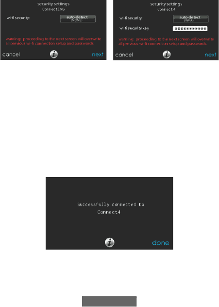
77
A13237
• If a Wi-Fi network security key is shown as on the right hand picture
above then select the white bar and enter the security key, then select
NEXT.
• Touch in the security key area, and the keyboard will appear.
– Use the on screen keyboard to enter the Wi-Fi network security key,
then touch NEXT.
• The control will inform you if the connection is successful. If so,
touch DONE.
– If the connection is unsuccessful, verify that the proper information
has been entered before you touch RETRY. The control will go
through the process again.
A13238
• After the control has connected to the network, go to
www.MyInfinityTouch.Carrier.com to register the unit or you can use
the Carrier® Home mobile app to begin remote access. This requires

78
the MAC address and serial number of the Infinity System Control. If
using the Carrier® Home mobile app you can just scan the QR Code
on the wall control and it will fill in the control information. To find
the serial number and MAC address on the Infinity System Control,
click on Menu, Down Arrow, Wireless and View MyInfinity
Registration Info. This screen will provide the information needed on
the MyInfinity website during registration or you can select the QR
code for use with the Carrier® Home mobile app.
A170285C
• If you have any issues, please contact your servicing dealer or contact
the support desk at 1-800-Carrier.
• When the connection to the MyInfinity web server has been
established, the status screen will show Connected for both Wi-Fi and
the server.

79
A13242C
A180093
Connected:
Not Connected:

80
8. Wiring Diagrams
A160107
Universal Four-Wire Connection
A
B
C
D
A
B
C
D
User Interface
Green - Data A
Yellow - Data B
White - COM
Red - 24VAC
OAT
Optional Remote
Room Sensor
HUM
COM
24V
Humidifier
Connection
S2
S1
A
B
C
D
ABCD
Connections
Communicating
AC, HP or GHP*
Green
Yellow
White
Red
OAT
Sensor
(Optional)
Variable-Speed
Furnace/ Fan Coil
127(6RPHRXWGRRUXQLWVGRQRWUHTXLUHWKHk&lDQGk'lFRQQHFWLRQV
6HHRXWGRRUXQLW,QVWDOODWLRQ,QVWUXFWLRQV
127()RU633SURGXFWV$%&'FRQQHFWLRQEHWZHHQ,QGRRUDQG2XWGRRU
FRQWUROERDUGVDUHSUHZLUHGDWWKHIDFWRU\
127()RUQHZ633LQVWDOODWLRQVLQZKLFKWKH2$76HQVRULVUHTXLUHG
SOHDVHUHIHUWRWKH633,QVWDOODWLRQ,QVWUXFWLRQV

81
A12354
Connection Diagram for Furnace or FE Fan Coil
with
1-Stage Air Conditioning
A
B
C
D
A
B
C
D
C
Y
ABCD
Connection
User Interface
1-Spd.
Non-Communicating
AC
Green - Data A
Yellow - Data B
White - COM
Red - 24VAC
Optional Remote
Room Sensor
HUM
COM
24V
Humidifier
Connection
Y/Y2
S2
S1
OAT
OAT
Sensor
Variable-Speed
Furnace/Fan Coil

82
A12355
Connection Diagram for FE Fan Coil with
Non-communication
1-Stage Heat Pump
A
B
C
D
A
B
C
D
ABCD
Connection
User Interface
1-Spd.
Non-communicating
HP
Green - Data A
Yellow - Data B
White - COM
Red - 24VAC
Optional Remote
Room Sensor
HUM
C
Humidifier
Connection
Y
S2
S1
W2
Y
O
C
R
O
R
W
OAT
OAT
Sensor
Variable-Speed
Fan Coil
G

83
A04018
Zoning Connection for Communicating Indoor
Unit with
2-Stage Communicating Outdoor Unit
NOTE: Some outdoor units do not require “C” and “D” connections.
Please see outdoor unit Installation Instructions.
A
B
C
D
Zone Control
User Interface &
Smart Sensor(s)
Green
Yellow
White
Red
OAT
HUM
COM
24V
Humidifier
Connection
A
B
C
D
OAT
Sensor
(Optional)
A B C D A B C D
Damper
Control
module
A B C D
Indoor
Unit
Communicating
AC or HP

84
A04019
Zoning Connection Diagram for Furnace or FE
Fan Coil with
Non-Communicating 1-Stage Air Conditioning
A
B
C
D
Zone Control
User Interface &
Smart Sensor(s)
Green
Yellow
White
Red
OAT
HUM
COM
24V
Humidifier
Connection
OAT
Sensor
A B C D A B C D
Damper
Control
module
A B C D
Indoor
Unit
C
Y
1-Stage AC.
Y/Y2

85
A07149
Zoning Connection Diagram for FE Fan Coil with
Non-communicating 1-Stage Heat Pump
A
B
C
D
Zone Control
User Interface &
Smart Sensor(s)
Green
Yellow
White
Red
A B C D A B C D
Damper
Control
module
A B C D
Variable-Speed
Fan Coil
1-Spd. HP
HUM
C
Y
W2
Y
O
C
R
O
R
W
OAT
OAT
Sensor
Humidifier
Connection
G

86
Zoning Connection Diagram for FE
A
B
C
D
B
G
R
Y
C
OVR
LED
12V
D-
D+
GND
12V
D-
D+
GND
W
O
Y1
R
Y2
A
B
C
D
B
G
R
Y
A
B
C
D
FUSE
YellowGreen
New ERV / HRV
Models
Translator Board
Furnace
System Wall
Control
Network Interface Module
(NIM)
A200528
Ventilator (HRV / ERV) Connection
A210310
87
Infinity® System
Control
HRV Product
Network Interface
Module
SYSTXCCNIM01
Translator Board
SYSTXXXTRB01
SYSTXCCITC01-B
SYSTXCCITC01-C
SYSTXCCWIC01-B
SYSTXCCICF01-B
SYSTXCCWIF01-B
HRVXXSVA1130 Required Required
HRVXXSHA1130 Required Required
HRVXXSVA1160 Required Required
HRVXXSHA1160 Required Required
HRVXXSVB1160 Required Required
HRVXXSHB1160 Required Required
HRVCRLHB1250 Required Not Required
Infinity® System
Control
ERV Product
Network Interface
Module
SYSTXCCNIM01
Translator Board
SYSTXXXTRB01
SYSTXCCITC01-B
SYSTXCCITC01-C
SYSTXCCWIC01-B
SYSTXCCICF01-B
SYSTXCCWIF01-B
ERVXXSVA1130 Required Required
ERVXXSHA1130 Required Required
ERVXXSVB1145 Required Required
ERVXXSHB1145 Required Required
ERVXXSVA1150 Required Required
ERVXXSHA1150 Required Required
ERVCRLHB1200 Required Not Required

88
A160170
NIM Chart
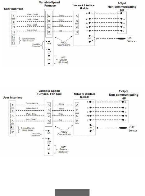
89
A160171
Wiring Diagram Single-Stage
Non-Communicating Heat Pump NIM
A160172
Wiring Diagram Two-Stage Non-Communicating
Heat Pump NIM

90
A07114
G Input Wiring for Blower Operation
R
G
FE Fan Coil or
Variable Speed Furnace

91
A07115
G Input Wiring for System Shutdown
9. Statement Information
This device complies with Part 15 of the FCC Rules. Operation is subject
to the following two conditions: (1) This device may not cause harmful
interference, and (2) This device must accept any interference received,
including interference that may cause undesired operation.
Changes or modifications not expressly approved by the party
responsible for compliance could void the user’s authority to operate the
equipment.
9.1. FCC Interference Statement
This equipment has been tested and found to comply with the limits for a
Class B digital device, pursuant to part 15 of the FCC Rules. These limits
R
G
FE Fan Coil or
Variable Speed Furnace

92
are designed to provide reasonable protection against harmful
interference in a residential installation. This equipment generates, uses
and can radiate radio frequency energy and, if not installed and used in
accordance with the instructions, may cause harmful interference to radio
communications. However, there is no guarantee that interference will
not occur in a particular installation. If this equipment does cause
harmful interference to radio or television reception, which can be
determined by turning the equipment off and on, the user is encouraged
to try to correct the interference by one or more of the following
measures:
• Reorient or relocate the receiving antenna.
• Increase the separation between the equipment and receiver.
• Connect the equipment into an outlet on a circuit different from that to
which the receiver is connected.
• Consult the dealer or an experienced radio/TV technician for help.
To comply with FCC/IC RF exposure limits for general population /
uncontrolled exposure, the antenna(s) used for this transmitter must be
installed to provide a separation distance of at least 20 cm from all
persons and must not be co-located or operating in conjunction with any
other antenna or transmitter.
Pour se conformer aux limites d’exposition RF FCC et IC pour la
population générale / l’exposition incontrôlée, l’antenne utilisée pour cet
émetteur doit être installée pour assurer une distance de séparation d’au
moins 20 cm de toutes les personnes et fonctionnant conjointement avec
toute autre antenne ou émetteur.
This Device complies with Industry Canada License-exempt RSS
standard(s). Operation is subject to the following two conditions: 1) this
device may not cause interference, and 2) this device must accept any
interference, including interference that may cause undesired operation
of the device.

93
Cet appareil est conforme avec Industrie Canada, exempts de licence
standard RSS (s). Son fonctionnement est soumis aux deux conditions
suivantes: 1) ce dispositif ne peut pas causer d’interférences, et 2) ce
dispositif doit accepter toute interférence, y compris les interférences qui
peuvent causer un mauvais fonctionnement de l’appareil.
Infinity®, True Sense, Smart Evap, and HYBRID HEAT® are trademarks or
registered trademarks of Carrier Corporation in the United States and other
countries. Other brands and product names are trademarks of their respective
holders.
Wi-Fi® is a registered trademark of Wi-Fi Alliance Corporation.
Amazon Alexa is a trademark of Amazon, Inc. or its affiliates.
The Bluetooth word mark and logos are owned by Bluetooth SIG, Inc.

© 2022 Carrier. All rights reserved.
Catalog No: SYSTXCCITC-12SI 997-017060-12-R
Edition Date: 05/22 Replaces: SYSTXCCITC-11SI
Manufacturer reserves the right to change, at any time, specifications and designs
without notice and without obligations.
94
