
CHAMPION
®
13-8-627
Version: 04
May 2, 2006
ROTORCHAMP
BASE-MOUNTED
COMPRESSORS
MODELS – EFD99A
40 & 50 HP
OPERATING AND
SERVICE MANUAL
13-8-627 Page ii
MAINTAIN COMPRESSOR RELIABILITY AND PERFORMANCE WITH
GENUINE CHAMPION
®
COMPRESSOR PARTS AND SUPPORT SERVICES
Champion Compressor genuine parts, manufactured to design tolerances, are developed for optimum dependability – specifically
for Champion compressor systems. Design and material innovations are the result of years of experience with hundreds of different
compressor applications. Reliability in materials and quality assurance are incorporated in our genuine replacement parts.
Your authorized Champion Compressor distributor offers all the backup you’ll need. A worldwide network of authorized distributors
provides the finest product support in the air compressor industry. Your local authorized distributor maintains a large inventory of
genuine parts and he is backed up for emergency parts by direct access to the Master Distribution Center (MDC) in Memphis,
Tennessee.
Your authorized distributor can support your Champion air compressor with these services:
1. Trained parts specialists to assist you in selecting the correct replacement parts.
2. Factory warranted new and remanufactured rotary screw airends. Most popular model remanufactured airends are maintained
in stock at the Remanufacturing Center in Indianapolis, IN., for purchase on an exchange basis with liberal core credit available
for the replacement unit.
3. A full line of factory tested RotorLub™ compressor lubricants specifically formulated for use in Champion compressors.
4. Repair and maintenance kits designed with the necessary parts to simplify servicing your compressor.
Authorized distributor service technicians are factory trained and skilled in compressor maintenance and repair. They are ready to
respond and assist you by providing fast, expert maintenance and repair services.
For the location of your local authorized Champion Air Compressor distributor, refer to the yellow pages of your phone
directory or contact:
Factory:
Champion
1301 N. Euclid Ave.
Princeton, IL. 61356
Phone: (815) 875-3321
Fax: (815) 872-0421
REMANUFACTURED AIRENDS
Whenever an airend requires replacement or repair, Champion offers an industry unique, factory remanufactured airend exchange
program. From its modern Remanufacturing Center in Indianapolis, IN., Champion is committed to supplying you with the highest
quality, factory remanufactured airends that are guaranteed to save you time, aggravation and money.
Immediately Available
Repair downtime costs you money, which is why there are over 200 remanufactured units in inventory at all times, ready for
immediate delivery.
Skilled Craftsmen
Our Remanufacturing assembly technicians average over 20 years experience with air compression products.
Precision Remanufacturing
All potentially usable parts are thoroughly cleaned, inspected and analyzed. Only those parts that can be brought back to original
factory specifications are remanufactured. Every remanufactured airend receives a new overhaul kit: bearings, gears, seals,
sleeves and gaskets.
Extensive Testing
Champion performs testing that repair houses just don’t do. Magnaflux and ultrasonic inspection spot cracked or stressed castings,
monochromatic light analysis exposes oil leaks, and coordinate measurement machine inspects to +/- .0001”, insuring that all
remanufactured airends meet factory performance specifications.
Warranty
Champion backs up every remanufactured airend with a new warranty…18 months from purchase, 12 months from service.
Champion remanufactured airends deliver quality without question…year in and year out.
Call Champion for information on the airend exchange program and the name of your authorized distributor.
Phone Number: (815) 875-3321
Fax: (815) 872-0421

13-8-627 Page iii
FOREWORD
Champion Rotary Screw compressors are the result of advanced engineering and skilled manufacturing.
To be assured of receiving maximum service from this machine the owner must exercise care in its
operation and maintenance. This book is written to give the operator and maintenance department
essential information for day-to-day operation, maintenance and adjustment. Careful adherence to these
instructions will result in economical operation and minimum downtime.
DANGER
Danger is used to indicate the presence of a hazard which will cause severe
personal injury, death, or substantial property damage if the warning is ignored.
WARNING
Warning is used to indicate the presence of a hazard which can cause severe
personal injury, death, or substantial property damage if the warning is ignored.
CAUTION
Caution is used to indicate the presence of a hazard which will or can cause
minor personal injury or property damage if the warning is ignored.
NOTICE
Notice is used to notify people of installation, operation or maintenance
information which is important but not hazard-related.
This book covers the following models:
HP PSI Air Cooled Parts List Controller Manual
40 & 50 100, 125, 150, 175 EFD99A 13-8-518 13-8-624
13-8-627 Page iv
TABLE OF CONTENTS
Maintain Compressor Reliability and Performance With Genuine Champion
Compressor Parts and Support Services.................................................................................................. ii
Remanufactured Airends .............................................................................................................................. ii
Foreword.......................................................................................................................................................iii
Index.............................................................................................................................................................. v
List Of Illustrations........................................................................................................................................vii
Section 1, General Information .....................................................................................................................1
Section 2, Installation....................................................................................................................................7
Section 3, Starting & Operating Procedures...............................................................................................14
Section 4, Controls & Instrumentation ........................................................................................................17
Section 5, Lubrication, Oil Cooler, Oil Filter & Separator............................................................................24
Section 6, Air Filter......................................................................................................................................35
Section 7, Belt Drive....................................................................................................................................37
Section 8, Maintenance Schedule ..............................................................................................................40
Section 9, Troubleshooting .........................................................................................................................42
13-8-627 Page v
INDEX
Air Cooled Unit...................................................8
Air Filter
Element.........................................................38
Element Life..................................................39
Section 6.......................................................38
Standard Duty...............................................38
Air Flow In Compressor System ........................1
Air Receiver
Auxiliary........................................................11
Air/Oil Separators.............................................35
Belt Drive
Checking Tension.........................................41
Replacing The Belts .....................................40
Replacing The Sheave.................................40
Section 7.......................................................40
Cold Ambient Operation...................................28
Cold Weather Operation, Installation For.........11
Compression Principle .......................................1
Compressor........................................................1
Controls & Instrumentation
Auto Sentry Operation..................................19
Changing Minimum Pressure/Check Valve
Seals.........................................................24
Control Devices ............................................21
General Description......................................19
Section 4.......................................................19
Cooler
Compressor Oil.............................................35
Cooling, Sealing And Lubrication.......................1
Daily Check......................................................18
Decals ............................................................6, 7
Discharge Service Line ....................................12
Electrical Wiring ...............................................12
Enclosure .........................................................10
Foundation .........................................................9
General Information
Section 1.........................................................1
Grounding.........................................................13
High Temperature Operation ...........................28
Inlet Line...........................................................11
Installation
General...........................................................8
Section 2.........................................................8
Lifting Unit ..........................................................8
Location..............................................................8
Lubricant
Recommended .............................................27
Upgrade Procedure......................................31
Lubrication
Motor ............................................................13
Lubrication, Cooling And Sealing.......................1
Lubrication, Oil Cooler, Oil Filter & Separator
Section 5 ......................................................27
Maintenance Schedule
Section 8 ......................................................43
Moisture Separator/Trap
Optional........................................................11
Motor Lubrication .............................................13
Oil Change Interval..........................................29
Oil Cooler
Compressor..................................................35
Oil Filter............................................................33
Oil Level
Gauge...........................................................33
Procedure For Checking ..............................28
Oil Reservoir ....................................................35
Drain...............................................................9
Filling............................................................30
Oil Separator
Inspection.....................................................36
Removal For Inspection Or Replacement....36
Oil Specifications .............................................27
Oil System
Addition Of Oil Between Changes................28
Compressor..................................................27
Draining And Cleaning .................................30
Moisture In System ......................................33
Oil System Check ............................................37
Air And Oil Discharge Temperature.............37
Compressor Oil Inlet Temperature...............37
Oil Cooler Oil Pressure Differential..............37
Oil Cooler Temperature Differential .............37
Oil Inlet Pressure..........................................37
Piping
Control..........................................................11
Pressure Differential Gauging..........................35
Prestart-Up Instructions...................................15
Air Filter........................................................15
Compressor Oil ............................................15
Electrical.......................................................15
Enclosure .....................................................16
Grounding.....................................................15
Operating Mode............................................16
Piping ...........................................................15
Rotation........................................................16
System Pressure..........................................16
Safety Precautions.............................................4
Sealing, Lubrication And Cleaning.....................1
Separators
13-8-627 Page vi
Air/Oil............................................................35
Service Check List ...........................................43
Air Filter ........................................................43
Every 1000 Hours Operation........................43
Every 125 Hours Operation..........................43
Every 4000 Hours Operation........................43
Every 8 Hours Operation..............................43
Every Year....................................................43
Motor Lubrication..........................................43
Sheave Alignment............................................41
Starting & Operating Procedures
Section 3.......................................................15
Starting The Unit ..............................................18
Unit Cold.......................................................18
Unit Hot ........................................................18
Stopping The Unit............................................18
Trouble Shooting
Section 9 ......................................................45
Troubleshooting Voltage Problems..................48
Valve
Thermal Control (Thermostatic Mixing)........35
Wiring
Electrical.......................................................12
13-8-627 Page vii
LIST OF ILLUSTRATIONS
Figure 1-1 – Compressor Cycle....................................................................................................................1
Figure 1-2 – Compressor Illustration.............................................................................................................2
Figure 2-1 – Typical Compressor Room.......................................................................................................8
Figure 2-2 – Air Flow Chart...........................................................................................................................8
Figure 2-3 – Cold Weather Installation .........................................................................................................9
Figure 4-1 – Control Schematic ..................................................................................................................17
Figure 4-2 – Key Pad ..................................................................................................................................18
Figure 4-3 – Wiring Diagram – Full Voltage................................................................................................22
Figure 4-4 – Wiring Diagram – Full Voltage................................................................................................23
Figure 5-1 – Flow Diagram..........................................................................................................................24
Figure 5-2 – Approximate Oil System Capacities.......................................................................................26
Figure 5-3 – Oil Change Interval.................................................................................................................26
Figure 5-4 – Oil Level Gauge, Oil Fill and Oil Drain....................................................................................30
Figure 5-5 – Oil Filter ..................................................................................................................................31
Figure 6-1 – Air Filter ..................................................................................................................................35
Figure 7-1 – Belt Tension – 3VX Belts........................................................................................................39

13-8-627 Page 1
SECTION 1
GENERAL INFORMATION
Figure 1-1 – COMPRESSOR CYCLE
COMPRESSOR - The rotary screw compressor is a single stage, positive displacement rotary machine
using meshing helical rotors to effect compression. Both rotors are supported between high capacity
roller bearings located outside the compression chamber. Single width cylindrical roller bearings are
used at the inlet end of the rotors to carry part of the radial loads. Ball and roller bearings at the
discharge end locate each rotor axially and carry all thrust loads and the remainder of the radial loads.
COMPRESSION PRINCIPLE (Figure 1-1) - Compression is accomplished by the main and secondary
rotors synchronously meshing in a one-piece cylinder. The main rotor has four (4) helical lobes 90° apart.
The secondary rotor has five (5) matching helical grooves 72° apart to allow meshing with main rotor
lobes.
The air inlet port is located on top of the compressor cylinder near the drive shaft end. The discharge port
is near the bottom at the opposite end of the compressor cylinder. Figure 1-1 is an inverted view to show
inlet and discharge ports. The compression cycle begins as the rotors unmesh at the inlet port and air is
drawn into the cavity between the main rotor lobes and the secondary rotor grooves (A). When the rotors
pass the inlet port cutoff, air is trapped in the interlobe cavity and flows axially with the meshing rotors (B).
As meshing continues, more of the main rotor lobe enters the secondary rotor grove, normal volume is
reduced and pressure increases.
Oil is injected into the cylinder to remove the heat of compression and seal internal clearances. Volume
reduction and pressure increase continues until the air/oil mixture trapped in the interlobe cavity by the
rotors passes the discharge port and is released to the oil reservoir (C). Each rotor cavity follows the
same “fill-compress-discharge” cycle in rapid succession to produce a discharge air flow that is
continuous, smooth and shock free.
AIR FLOW IN THE COMPRESSOR SYSTEM (Figure 5-1, page 24) - Air enters the air filter and passes
through the inlet unloader valve and on into the compression chamber where oil is injected into the air.
After compression, the air/oil mixture passes into the oil reservoir where most of the entrained oil is
removed by velocity change and impingement and drops back into the reservoir. The air and remaining
oil then passes through the air/oil separator. The air then passes through the minimum pressure/check
valve, the aftercooler and the moisture separator and into the plant air lines.
LUBRICATION, COOLING AND SEALING - Oil is forced by air pressure from the oil reservoir through
the oil cooler, thermostatic mixing valve, and oil filter and discharge into the compressor main oil gallery.
A portion of the oil is directed through internal passages to the bearings and shaft oil seal. The balance
of the oil is injected directly into the compression chamber to remove heat of compression, seal internal
clearances and lubricate the rotors.

13-8-627 Page 2
Figure 1-2 – COMPRESSOR ILLUSTRATION
300EFD797-
A
(Ref. Drawing)
13-8-627 Page 3
SAFETY PRECAUTIONS
Safety is everybody’s business and is based on your use of good common sense. All situations or
circumstances cannot always be predicted and covered by established rules. Therefore, use your past
experience, watch out for safety hazards and be cautious. Some general safety precautions are given
below:
DANGER
Failure to observe these notices could result in injury to or death of personnel.
• Keep fingers and clothing away from revolving fan, drive coupling, etc.
• Do not use the air discharge from this unit for breathing – not suitable for
human consumption.
• Do not loosen or remove the oil filler plug, drain plugs, covers, the
thermostatic mixing valve or break any connections, etc., in the compressor
air or oil system until the unit is shut down and the air pressure has been
relieved.
• Electric shock can and may be fatal.
• Perform all wiring in accordance with the National Electrical Code (NFPA-70)
and any applicable local electrical codes. Wiring and electrical service must
be performed only by qualified electricians.
• Open the main disconnect switch, lockout and tagout before working on the
control.
• Disconnect the compressor unit from its power source, lockout and tagout
before working on the unit – this machine is automatically controlled and
may start at any time.

13-8-627 Page 4
WARNING
Failure to observe these notices could result in damage to equipment.
• Stop the unit if any repairs or adjustments on or around the compressor are
required
• Disconnect the compressor unit from its power source, lockout and tagout
before working on the unit – this machine is automatically controlled and
may start at any time.
• An Excess Flow Valve should be on all compressed air supply hoses
exceeding 1/2 inch inside diameter. (OSHA Regulation, Section 1926.302, or
local regulations)
• Do not exceed the rated maximum pressure values shown on the nameplate.
• Do not operate unit if safety devices are not operating properly. Check
periodically. Never bypass safety devices.

13-8-627 Page 5
DECALS
206EAQ077
212EAQ077
218EAQ077
211EAQ077
207EAQ077

13-8-627 Page 6
DECALS
216EAQ077
217EAQ077
222EAQ077
221EAQ077
208EAQ077
13-8-627 Page 7
SECTION 2
INSTALLATION
GENERAL - On receipt of the unit, check for any damage that may have been incurred during transit.
Report any damage or missing parts as soon as possible.
CAUTION
Do not electric weld on the compressor or base; bearings can be damaged by
passing of current.
LIFTING UNIT - Proper lifting and/or transporting methods must be used to prevent damage. Unit may
be moved into location by lift truck.
CAUTION
Lift compressor unit by base only. Do not use other places such as motor,
compressor or discharge manifold piping as lifting points.
DANGER
The eyebolts or lugs provided on the motor are for lifting the motor only and
should not be used to lift any additional weight. All eyebolts must be securely
tightened. When lifting the motor the lifting angle must not exceed 15 degrees.
Failure to observe this warning may result in damage to equipment or personal
injury.
LOCATION (Figure 2-1, page 8) - The compressor should be installed where it is protected from rain,
snow and freezing temperatures, in a clean, well-lighted, well-ventilated area with ample space all
around, including above, for maintenance. If a low ceiling is encountered, the hot discharge air may need
to be ducted out to avoid recirculation. Select a location that provides a cool, clean, dry source of air. In
some cases it may be necessary to install the air filter at some distance from the compressor to obtain
proper air supply.
AIR-COOLED UNIT - A combination oil/aftercooler is supplied as standard equipment on all air-cooled
units. The air-cooled unit with the standard enclosure requires sufficient flow for the compressor
oil/aftercooling system and electric motor cooling (Figure 1-2, page 2). Air is drawn into the unit above
the motor and discharged through the cooler. Do not block the air flow to and from the unit. Allow three
and one half (3-1/2) feet to the nearest obstruction on the control box end of the unit. Allow two (2) feet to
the nearest obstruction above and on other sides of unit.
For continuous efficiency, oil cooler cores must be periodically cleaned with either vacuum or compressed
air. If wet cleaning is required, shield motor and spray on a mild soap solution and flush with clean water.

13-8-627 Page 8
WARNING
For aluminum oil coolers, do not use any cleaning solution that is not
compatible with aluminum. Use of improper solution may result in damage to
the cooler.
Figure 2-1 – TYPICAL COMPRESSOR ROOM
Minimum Air Flow* For Compressor
And Cooling (cubic Feet/Minute)
Air Cooled
All Models 4800 cfm
* 80° F Inlet Air
Figure 2-2 – AIR FLOW CHART
FOUNDATION - The rotary screw compressor requires no special foundation, but should be mounted on
a smooth, solid surface. Whenever possible install the unit near level. Temporary installation may be
made at a maximum 5° angle lengthwise or 5° sidewise. Mounting bolts are not normally required.
However, installation conditions such as piping rigidity, angle of tilt, or danger of shifting from outside
vibration or moving vehicles may require the use of mounting bolts and shims to provide uniform support
for the base. Belt alignment and tension should be checked after installation. (For information on belt
alignment and tension, see SECTION 7, page 37.
OIL RESERVOIR DRAIN - The oil drain is piped from the bottom of the reservoir to the side of the frame.
This drain is approximately 20 inches above the floor level.
13-8-627 Page 9
CAUTION
If the compressor unit base is raised above floor level, the space between the
floor and the base bottom must be closed with solid material all around to
prevent recirculation of hot air from the oil cooler end and over temperature
operation.
ENCLOSURE - The compressor, electric motor, oil cooler and aftercooler are mounted inside the
enclosure.
Service panels are provided for maintenance access. Be sure to allow enough space around the unit for
the panels to be removed. Any of the enclosure panels may be removed by opening the latch and lifting it
up slightly.
DANGER
Do not operate the compressor with the fan and belt guard removed. Exposed
fan and belts may cause injury to personnel.
CAUTION
The enclosure doors and panels must be closed and latched while the
compressor is operating. Failure to close and latch the doors and panels will
cause high temperature shutdowns.
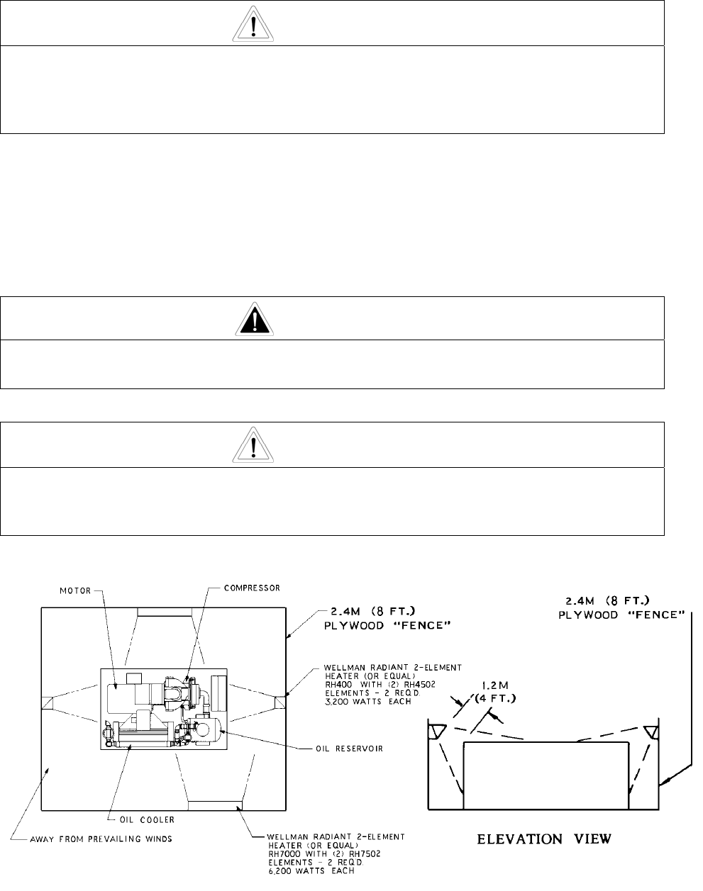
Figure 2-3 – COLD WEATHER INSTALLATION
13-8-627 Page 10
INSTALLATION FOR COLD WEATHER OPERATION (Figure 2-3, page 9) - It is recommended that the
unit be installed inside a shelter that will be heated to temperatures above freezing (32
o
F, 0
o
C). This will
eliminate many of the problems associated with operating units in cold climates, such as freezing in
control lines and downstream of the cooler.
Refer to Engineering Data Sheet 13-9-411 for the advantages of using the heat recovered from rotary
compressors. This heat recovery could easily pay for an adequate shelter for the unit.
When an outside installation must be made, the precautions required will depend on the severity of the
environment. The following are general guidelines for outside installations:
Cold Weather (Down To +10
o
F)
1. Be sure all drains, traps, and control lines, including pressure transducer lines are heated to avoid
freezing of condensate. Heat tape with thermostat control is generally satisfactory for this purpose
and can be obtained at various local plumbing or hardware outlets at nominal cost.
2. Provisions to bypass the aftercooler must be made. Since cold air contains very little moisture,
successful operation can be achieved without the aftercooler.
3. Provide at least some simple shelter such as a plywood windbreak to protect against drifting snow.
4. Use only Champion RotorLub 8000 lubricant.
5. Monitor unit carefully during start-up and operation to be sure it is functioning normally.
Remember unsheltered (outside) installations should be avoided where possible. Installation next to a
heated building where enough heat can be used to keep the compressor room above freezing will save
many complications in the operation and installation of the unit.
AUXILIARY AIR RECEIVER - An auxiliary air receiver is not required if the piping system is large and
provides sufficient storage capacity to prevent rapid cycling. When used, an air receiver should be of
adequate size, provided with a relief valve of proper setting, a pressure gauge and a means of draining
condensate
STANDARD MOISTURE SEPARATOR/TRAP - The unit is equipped with a built-in aftercooler, a
combination moisture separator and trap piped into the system down stream of the aftercooler.
CONTROL PIPING - Control piping is not necessary since the rotary screw unit is factory wired and piped
for the control system specified.
INLET LINE - Where an inlet line is used between the air filter and the compressor, it must be thoroughly
cleaned on the inside to prevent dirt or scale from entering the compressor. If welded construction is
used, the line must be shot blasted and cleaned to remove welding scale. In either case, the inlet
line must be coated internally by galvanizing or painting with a moisture and oil-proof sealing lacquer. Up
to ten (10) feet in length, the inlet line should be the full size of the inlet opening on the compressor. If an
extra-long line is necessary, the pipe size should be increased according to “Inlet Line Length Chart”,
page 11.
Accessibility for inlet air filter servicing must be considered when relocating the filters from the unit to a
remote location.

13-8-627 Page 11
INLET LINE LENGTHS
Length of Inlet Line Diameter of Pipe Size
0 to 10 Feet ............................................. Same as Compressor Inlet Opening
10 to 17 Feet ........................................... One Size Larger Than Inlet Opening
17 to 38 Feet ........................................... Two Sizes Larger Than Inlet Opening
DISCHARGE SERVICE LINE - The discharge service line connection is made at the left hand corner of
the package when viewed from the control box end. A hand operated valve, (air service valve) must be
installed between the unit and the customer’s air system. If a fast operating valve such as a ball valve is
used, it must be closed slowly to give the intake valve time to shut and keep the discharge pressure from
spiking.
WARNING
The controller has an automatic start/stop sequence built in. You do NOT need
to close the air service valve. Closing the air service valve on start-up or prior
to shutdown will cause rapid cycling, and could cause a high pressure
shutdown.
When manifolding two or more rotary screw units on the same line, each unit is isolated by the check
valve in the unit discharge line.
If a rotary screw unit is manifolded to another compressor, be sure the other compressor has a check
valve in the line between the machine and the manifold.
If a rotary screw and a reciprocating compressor are manifolded together, an air receiver must be located
between the two units.
DANGER
Discharge air used for breathing will cause severe injury or death.
Consult filtration specialists for additional filtration and treatment equipment to
meet health and safety standards.
ELECTRICAL WIRING - Standard Units - The compressor package is factory wired for all connections
from the starter to the motor, for the horsepower and voltage specified on the order. The standard unit is
supplied with open drip proof motors, and a NEMA 12 starter and controls enclosure. Totally enclosed
motors and NEMA 4 enclosures are available as factory options. See “Location” paragraph on page 7,
for distance to the nearest obstruction on the control box side of the package.
Perform all wiring in accordance with the National Electrical Code (NFPA-70) and any applicable local
electrical codes. Wiring must be performed only by qualified electricians.

13-8-627 Page 12
WARNING
Electrical shock can cause injury or death. Open main disconnect switch,
lockout and tagout before working on control box.
GROUNDING - Equipment must be grounded in accordance with Section 250 of the National Electrical
Code.
WARNING
Failure to properly ground the compressor package could result in injury or
death. Install ground wiring in accordance with the National Electrical Code
and any applicable local codes.
MOTOR LUBRICATION - Long time satisfactory operation of an electric motor depends in large measure
on proper lubrication of the bearings. The following charts show recommended grease qualities and
regreasing intervals for ball bearing motors. For additional information, refer to the motor manufacturer’s
instructions.
The following procedure should be used in regreasing:
1. Stop the unit.
2. Disconnect, lockout and tagout the unit from the power supply.
3. Remove the relief plug and free hole of hardened grease.
4. Wipe lubrication fitting clean and add grease with a hand-operated grease gun.
5. Leave the relief plug temporarily off. Reconnect unit and run for about 20 minutes to expel the
excess grease.
6. Stop the unit. Replace the relief plug.
7. Restart the unit.
WARNING
Rotating machinery can cause injury or death. Open main disconnect, lockout
and tagout power supply to starter before working on the electric motor.

13-8-627 Page 13
ELECTRIC MOTOR GREASE RECOMMENDATIONS (-30° C to 50° C)
MANUFACTURER TRADE NAME
CHEVRON SRI #2
SHELL DOLIUM R
EXXON UNIREX #2
EXXON POLYREX
ELECTRIC MOTOR REGREASING INTERVAL
Type of
Service
Typical
Rating
Relubrication Interval
Up to 150 HP (112 KW) 18 Months
Standard One or Two Shift Operation
Above 150 HP (112 KW) 12 Months
Up to 150 HP (112 KW) 9 Months
Severe Continuous Operation
Above 150 HP (112 KW) 6 Months
Up to 150 HP (112 KW) 4 Months
Very Severe
Dirty Locations, High Ambient
Temperature
Above 150 HP (112 KW) 2 Months

13-8-627 Page 14
SECTION 3
STARTING & OPERATING PROCEDURES
PRESTART-UP INSTRUCTIONS - A new unit as received from the factory has been prepared for
shipping only. Do not attempt to operate the unit until checked and serviced as follows:
1. Compressor Oil - The oil must be checked before starting the unit and every 8 hours of operation.
For instructions on checking the oil and the proper oil level, refer to “Compressor Oil Filter”, Section
5, page 24.
Do not mix different type oils. Unit is shipped filled with Champion RotorLub 4000 Lubricating
Coolant which is suitable for the first 4000 hours under normal operating conditions. RotorLub 8000
is also available. Check the decal on the reservoir to be sure which lubricant is in the machine.
REPLACE OIL FILTER EVERY 1000 HOURS.
NOTICE
Regular maintenance and replacement at required intervals of the oil filter, air
filter and air/oil separator is necessary to achieve maximum service and
extended drain intervals of RotorLub 4000 lubricant. Use only genuine
Champion filters designed and specified for this compressor.
DANGER
Always stop the unit and release air pressure before removing oil filler plug.
Failure to release pressure may result in personal injury or death.
2. Air Filter - Inspect the air filter to be sure it is clean and tightly assembled. Refer to SECTION 6,
page 35 for complete servicing instructions. Be sure the inlet line, if used, is tight and clean.
3. Piping – Refer SECTION 2, page 11 “Discharge Service Line” and make sure all piping meets all
recommendations.
4. Electrical - Check the wiring diagrams furnished with the unit to be sure it is properly wired. See
Figure 4-3, page 22 and Figure 4-4, page 23, for general wiring diagrams and page 11, for “Electrical
Wiring”.
5. Grounding - Unit must be properly grounded according to Section 250 of the National Electrical
Code.
WARNING
Failure to properly ground the compressor package could result in controller
malfunction.

13-8-627 Page 15
6. Rotation - Check for correct motor rotation by jogging the motor. See “Unit Setup Adjustments” in
the Controller Operating and Service Manual. Compressor drive shaft rotation must be clockwise,
standing facing the compressor sheave.
WARNING
Operation with incorrect motor rotation can damage equipment and cause oil
eruption from the compressor inlet. When checking motor rotation, induce
minimum rotation (less than one revolution if possible). Never allow motor to
reach full speed.
WARNING
The compressor unit’s direction of rotation must be check every time the
compressor is reconnected to the power supply.
7. System Pressure - The discharge pressure of the unit is set at the factory. To change the
discharge pressure, set the controls to the desired load pressure. DO NOT EXCEED THE
MAXIMUM OPERATING PRESSURE ON THE COMPRESSOR NAMEPLATE. See “Operation
Adjustments” in the Controller Operating and Service Manual.
WARNING
Operation at excessive discharge air pressure can cause personal injury or
damage to equipment. Do not adjust the full discharge air pressure above the
maximum stamped on the unit nameplate.
8. Operating Mode - Refer to SECTION 4, page 17 for detailed information on the control system.
9. Enclosure - Check for damaged panels or doors. Check all screws and latches for tightness. Be
sure doors are closed and latched.
DANGER
The compressor starts and stops automatically. Automatic restarting can
cause injury or death. Open, lockout and tagout main disconnect and any other
circuits before servicing the unit.
WARNING
The enclosure doors must be in place and fastened down to keep the
compressor package from overheating when the compressor is running.

13-8-627 Page 16
STARTING THE UNIT - Observe the following starting procedures:
WARNING
After an emergency stop, be sure that the pressure in the air/oil reservoir is less
than 5 psig. Wait one minute or more before restarting.
WARNING
The controller has an automatic start/stop sequence built in. You do NOT need
to close the air service valve. Closing the air service valve on start-up or prior
to shutdown will cause rapid cycling, and could cause a high pressure
shutdown.
Unit Cold:
1. Open the air service valve (customer furnished) between the main air system and the check valve on
the package.
2. Turn on power to the compressor package. To start press STOP/RESET, then press RUN.
3. Run for approximately five minutes or until the temperature stabilizes.
The unit is equipped with a minimum (70 psig) pressure/check valve. No special procedure is
required to maintain the unit reservoir pressure.
Unit Hot (No warm-up period is required):
1. Open the air service valve (customer furnished) between the main air system and the check valve on
the package.
2. Run for approximately one minute. The unit is equipped with a minimum (70 psig) pressure/check
valve, no special procedure to maintain the unit reservoir pressure is required.
DAILY CHECK - Refer to “Maintenance Schedule,” SECTION 8, page 40.
STOPPING THE UNIT:
1. To stop compressor operation, press STOP/RESET.
2. Wait approximately one minute to allow the compressor to stop. The oil reservoir will automatically
blow down as the motor stops.

13-8-627 Page 17
SECTION 4
CONTROLS & INSTRUMENTATION
GENERAL DESCRIPTION
The Champion rotary screw compressor is prewired with all controls, motor, and starter for the voltage
and horsepower at the time of ordering. It is necessary only to connect the compressor unit to the correct
power supply and to the shop air line. A standard compressor unit consists of the compressor, oil
reservoir, oil cooling system and filter, motor type as specified, NEMA 12 starter / control box, and control
components as described below.
AUTO SENTRY
®
OPERATION
Operation of the "AUTO SENTRY
®
" is dependent on selection of an operating mode from the controller
keypad. Prior to starting, the STOP/RESET key must be pressed to place the controller into its READY
state (as indicated on the display). Compressor operation may then be started by pressing the RUN key.
While in any operating mode, the display will indicate the mode, and the operating light will be on.
Press the STOP/RESET key at any time to stop the compressor under normal conditions.
AUTOMATIC is the most common selected mode of operation, as it automatically will operate the
compressor unit in the most efficient manner for the demand of the air system. Refer to the controller
manual for descriptions of other modes.
WARNING
Automatic restarting or electrical shock can cause injury or death. Disconnect,
lockout and tagout the unit from the power supply and any other circuits before
servicing unit.
Figure 4-1 – CONTROL SCHEMATIC
301EFD797-D
(Ref. Drawing)

13-8-627 Page 18
CONTROL DEVICES
Controller - This compressor unit features the "AUTO SENTRY
®
" controller, which integrates all the
control functions under microprocessor control. Its functions include safety and shutdown, compressor
regulation, operator control, and advisory/maintenance indicators. The keypad and display provide the
operator with a logical and easily operated control of the compressor and indication of its condition. The
controller is factory adjusted for the compressor package, but allows tuning for specific applications.
Detailed instructions for the controller are found in the “Auto Sentry” Controller Operating and Service
Manual.
Figure 4-2 – KEY PAD
Relief Valve - A pressure relief valve is installed in the final discharge line and set to approximately 120-
125% of the unit's full load operating pressure for protection against overpressure. Periodic checks
should be made to ensure its operation.
The relief valve should be tested for proper operation at least once every year. To test the relief valve,
raise the system operating pressure to 75% of the relief valve set pressure and manually open the valve
by turning the cap.
WARNING
When the relief valve opens, a stream of high velocity air is released, resulting
in a high noise level and possible discharge of accumulated dirt or other debris.
Always wear eye and ear protection and stand clear of the discharge port when
testing the relief valve to prevent injury.
CAUTION
Never paint, lubricate or alter a relief valve. Do not plug vent or restrict
discharge.
WARNING
Operation of the unit with improper relief valve setting can result in severe
personal injury or machine damage. Ensure properly set valves are installed
and maintained.

13-8-627 Page 19
Oil Level Gauge - This gauge is located on the oil reservoir and indicates the oil level. See “Oil Level
Gauge”, Figure 5-4, page 30, for how to read oil level.
Minimum Discharge Pressure/Check Valve - An internal spring-loaded minimum pressure valve is used
in the final discharge line to provide a positive pressure on the coolant system of the compressor even if
the air service valve is fully open to atmospheric pressure. This valve also functions as a check valve to
prevent back flow of air from the shop air line when the unit stops, unloads, or is shut down.
The valve incorporates an orifice which, when air is flowing through it, maintains pressure in the oil
reservoir. A spring-loaded piston valve senses air pressure on the upstream (reservoir) side of the valve.
When the system pressure rises, the spring is overridden and the valve opens to full porting.
Inlet Valve (Figure 4-1, page 17) - The Inlet valve restricts the inlet to control delivery and closes to
unload the compressor. At shutdown, the inlet valve closes to prevent the back flow of air.
The inlet valve position is controlled by air pressure in its piston cylinder, which is controlled by the
"AUTO SENTRY
®
" through the magnetic unloader solenoid valve. When the top of the cylinder is
pressurized, the inlet opens for full air delivery. When pressure is relieved from the cylinder, the inlet
valve closes to restrict air flow and compressor delivery.
Magnetic Unloader Solenoid Valve (Figure 4-1, page 17) - This valve controls the position of the inlet
valve in response to signals from the "AUTO SENTRY
®
". When de-energized, pressure is relieved from
the top of the inlet valve cylinder to unload the compressor. When the solenoid valve is energized,
reservoir pressure is supplied to the top of the cylinder to load the compressor.
Check Valve (Figure 4-1, page 17) - This valve is normally closed while the compressor is loaded or
stopped. While running unloaded, it opens to admit a small amount of purge air to the compressor inlet.
This reduces compressor knock, and provides enough air to pressurize the controls during startup.
Blowdown Valve (Figure 4-1, page 17) - The blowdown valve is a two-way solenoid valve which is piped
into the oil reservoir outlet ahead of the minimum pressure valve. When the solenoid is de-energized, the
valve opens and the coolant system is blown down. When the solenoid is energized, the valve closes to
allow the coolant system to pressurize.
Purge Air Valve (Figure 4-1, page 17) – The purge valve is a two-way solenoid valve that admits purge
air from the final discharge manifold to the compressor to counteract the oil knock that occurs in oil-
flooded rotary screw compressors when they are completely unloaded with pressure in the oil reservoir.
This valve is controlled by the controller which allows air into the airend whenever the inlet valve closes.
System Pressure Transducer (Figure 4-1, page 17) - This transducer is connected after the minimum
pressure valve. It converts the pressure in the plant air system into an electrical signal for use by the
"AUTO SENTRY
®
" controller for modulation and control.
Reservoir Pressure Transducer (Figure 4-1, page 17) - This transducer is connected to the coolant
system. Its signal is used to prevent loaded starts, monitor oil pressure, and to monitor the condition of
the separator.
Air Filter Vacuum Switch (Figure 4-1, page 17) - This switch is used to monitor air filter condition and
alert the user if the filter requires service or replacement.
CAUTION
Machine damage will occur if compressor is repeatedly restarted after any one
of the shutdown modes stops operation of the unit. Find and correct the
malfunction before resuming operation.

13-8-627 Page 20
Discharge Thermistor (Figure 4-1, page 17) - This sensor is located directly in the compressor
discharge. Its signal is used to monitor compressor temperature and shut down the compressor if a
coolant problem is detected.
Reservoir Thermistor (Figure 4-1, page 17) - This sensor is located in the reservoir/separator housing
and is used to monitor temperature and shut down the compressor if temperature problems occur at the
separator.
Emergency Stop Pushbutton - This is a maintained pushbutton, and removes power from the controller
outputs regardless of controller status. It is located on the upper section of the control box door, next to
the keypad. This should be used for emergency purposes only - use the keypad [STOP/RESET] for
normal controlled stopping.
WARNING
Automatic restarting or electrical shock can cause injury or death. Open and
lock main disconnect and any other circuits before servicing unit.
Control Transformer - This changes the incoming power voltage to 110-120 volts for use by all unit
control devices. Two primary and one secondary fuse are provided. Refer to adjacent labeling for
replacement information.
Terminal Strip - This provides connections for all 110-120 volt devices not contained within the
enclosure.
Main Starter - This starter is used to provide control and overload protection for the main drive motor.
Standard full voltage starters employ a single contactor and overload protection for each motor. Overload
heaters should be selected and adjusted based on the motor nameplate amps and the instructions
located inside the control box door.

13-8-627 Page 21
Changing Minimum Pressure/Check Valve Seals
DANGER
Air/oil pressure will cause severe personal injury or death. Shut down
compressor, relieve system of all pressure, disconnect, lockout and tagout
power supply to the starter before removing valves, caps, plugs, fittings, bolts
and filters.
1. Be sure the unit is completely off and that no air pressure is in the oil reservoir. Close the service
valve.
2. Disconnect, lockout and tagout the power supply to the starter.
3. Tighten the nut down on the minimum pressure/check valve cover.
4. Remove the four (4) bolts holding the cover onto the separator housing.
5. Remove the snap ring in the cover.
6. Remove the internal parts (see Parts List Book) and replace the seals in the minimum
pressure/check valve.
7. Re-assemble valve, including the snap ring.
8. Tighten the cover down to the separator housing.
9. Loosen the nut on top of the minimum pressure/check valve .05 to .08 inches.
10. Run the unit and check for leaks.

13-8-627 Page 22
Figure 4-3 – WIRING DIAGRAM – FULL VOLTAGE
300EFD546-C
(Ref. Drawing)
Page 1 of 2

13-8-627 Page 23
Figure 4-4 – WIRING DIAGRAM – FULL VOLTAGE
300EFD546-C
(Ref. Drawing)
Page 2 of 2

13-8-627 Page 24
SECTION 5
LUBRICATION
OIL COOLER, OIL FILTER & SEPARATOR
COMPRESSOR OIL SYSTEM (Figure 5-1) The compressor oil system cools the compressor, lubricates
moving parts and seals internal clearances in the compression chamber.
Air pressure in the oil reservoir forces oil through the oil cooler, thermostatic mixing valve, oil filter and into
the compressor main oil gallery.
The oil passes through internal passages for lubrication, cooling and sealing. The air-oil mixture is then
discharged to the oil reservoir where a large part of the entrained oil drops out of the air stream. The
remaining mixture then passes through the final oil separator where most of the remaining oil is removed.
The air then passes to the aftercooler. The oil separated from the air is sent to the oil cooler and
recirculated throughout the system. Oil separated at the air/oil separator is sent via an oil return line
through an orifice and back into the compressor.
RECOMMENDED LUBRICANT - Champion compressors are factory filled with RotorLub lubricants.
These lubricants are formulated to the highest quality standards and are factory authorized, tested and
approved for use in rotary screw compressors. RotorLub lubricants are available through your authorized
Champion compressor distributor.
Figure 5-1 – FLOW DIAGRAM
OIL SPECIFICATIONS - The recommended compressor lubricant is Champion RotorLub 4000
Lubricating Coolant which can be used for year-round operation except as noted in the “High
Temperature Operation” paragraph, page 25, or low temperature, see “Installation for Cold Weather
Operation,” page 10. RotorLub 4000 Lubricating Coolant is a superior petroleum base lubricant
formulated and containing additives for use in Champion compressors.
Ref.
No. Description
1 Air/oil Separators
2 Oil Scavenge Line
3 Orifice
4 Oil Filter
5 Thermostatic Mixing
Valve
6 Minimum
Pressure/Check Valve
7 Aftercooler
8 Oil Cooler
9 Moisture Separator
10 Drain
11 Pressure Relief Valve
13-8-627 Page 25
CAUTION
Specific RotorLub™ lubricants are recommended for use in this equipment.
Other lubricants may cause excessive carryover or compressor damage. Do
not mix different types of lubricants or use inferior lubricants. Check the decal
on the oil reservoir for lubricating coolant specification.
HIGH TEMPERATURE OPERATION - If the discharge temperature is sustained between 200° F-210° F.
for a period of more than four (4) hours due to continuing high ambient air temperature, use Champion
RotorLub 8000 Lubricating Coolant which is a superior synthetic lubricant. Short periods of up to four (4)
hours of sustained discharge temperatures up to 210° F. do not require a change from the recommended
year-round lubricant RotorLub 4000.
COLD AMBIENT OPERATION - See “Installation for Cold Weather Operation,” page 10 and Figure 2-3,
page 9.
PROCEDURE FOR CHECKING OIL LEVEL (Figure 5-4, page 30) - Check the oil level when the
compressor is shutdown and the oil/air mixture has separated. The oil should be visible in the white
range (a flashlight must be used) of the gauge. If there is only red showing on the gauge, the oil level is
too high and must be drained. If the oil level is in the red range below the white range, the oil level is too
low and oil must be added.
ADDITION OF OIL BETWEEN CHANGES – Oil must be added when the oil level is below the min. range
on the oil gauge. The oil must be checked with the machine shutdown, blowndown and the air/oil mixture
settled out to air and oil.
DANGER
Air/oil under pressure will cause severe personal injury or death. Shut down
compressor, relieve system of all pressure, disconnect, lockout and tagout
power supply to the starter before removing valves, caps, plugs, fittings, bolts
and filters.
DANGER
Compressor, air/oil reservoir, separation chamber and all piping and tubing
may be at high temperature during and after operation.
CAUTION
Excessive oil carryover can damage equipment. Never fill oil reservoir above
the max. range of the gauge.
To add oil, follow these steps:
1. Be sure the unit is completely off and that no air pressure is in the oil reservoir.
2. Disconnect, lockout and tagout the power supply to the starter.

13-8-627 Page 26
3. Wipe away all dirt around the oil filler plug. It is located by the oil filter.
4. Remove the oil filler plug and add oil as required to return the oil level to the max. line on the site
glass.
5. Install the oil filler plug, run and check for leaks.
DO NOT OVERFILL. The quantity required to raise the oil level from the red range to the white range is
three (3) quarts (Figure 5-2, page 26). Repeated addition of oil between oil changes may indicate
excessive oil carryover and should be investigated.
Use only CLEAN containers and funnels so no dirt enters the reservoir. Provide for clean storage of oils.
Changing the oil will be of little benefit if done in a careless manner.
40 to 50 HP (30 to 37 KW)
Refill Capacity For Normal Oil Change 3 U. S. Gallons (11 Liters)
Bottom of Site Glass to Top of Site Glass 3 U. S. Quart (3 Liters)
Figure 5-2 – APPROXIMATE OIL SYSTEM CAPACITIES
OIL CHANGE INTERVAL - Recommended oil change intervals are based on oil temperature. Figure 5-3,
shows how the change interval is affected by temperature.
When operating conditions are severe (very dusty, high humidity, etc.), it will be necessary to change the
oil more frequently. Operating conditions and the appearance of the drained oil must be surveyed and
the oil change intervals planned accordingly by the user. Champion offers a free oil analysis program
with the RotorLub lubricants and we recommend a sample be sent in at 100 hours on a new unit.
Discharge
Temperature
RotorLub™ 4000
Change Interval
RotorLub™ 8000
Change Interval
Up to 180° F (82° C)
4000 hrs. 8000 hrs.
180° F to 190° F (82° C to 88° C)
3000 hrs. 6000 hrs.
190° F to 200° F (88° C to 93° C)
2000 hrs. 4000 hrs.
200° F+ (93° C)
1000 hrs. 2000 hrs.
Figure 5-3 – OIL CHANGE INTERVAL

13-8-627 Page 27
DRAINING AND CLEANING OIL SYSTEM
DANGER
Air/oil under pressure will cause severe personal injury or death. Shut down
compressor, relieve system of all pressure, disconnect, lockout and tagout
power supply to the starter before removing valves, caps, plugs, fittings, bolts
and filters.
Always drain the complete system. Draining when the oil is hot will help to prevent varnish deposits and
carry away impurities.
To drain the system:
1. Be sure the unit is completely off and that no air pressure is in the air/oil reservoir.
2. Disconnect, lockout and tagout the power supply to the starter.
3. Stick the end of the drain tube into a suitable container, such as a 5 gallon pail.
4. Open the drain valve and allow oil to drain out of the air/oil reservoir.
5. Close the drain valve.
If the drained oil and/or the oil filter element are contaminated with dirt, flush the entire system: the
reservoir, oil cooler and lines. Inspect the air/oil separator element for dirt accumulation; replace if
necessary. If a varnish deposit exists, contact the factory for recommendations for removal of the deposit
and prevention of varnish.
FILLING OIL RESERVOIR
DANGER
Air/oil under pressure will cause severe personal injury or death. Shut down
compressor, relieve system of all pressure, disconnect, lockout and tagout
power supply to the starter before removing valves, caps, plugs, fittings, bolts
and filters.
DANGER
Compressor, air/oil reservoir, separation chamber and all piping and tubing
may be at high temperature during and after operation.
1. Be sure the unit is completely off and that no air pressure is in the oil reservoir.
2. Disconnect, lockout and tagout the power supply to the starter.

13-8-627 Page 28
3. Wipe away all dirt around the oil filler plug.
4. Remove the oil filler plug and add oil as required to return the oil level to the white range on the oil
gauge.
5. Install the oil filler plug and operate the unit for about a minute allowing oil to fill all areas of the
system. Check for leaks.
6. Shut down unit, allowing the oil to settle, and be certain all pressure is relieved.
7. Add oil, if necessary, to bring level to the white range on the oil level gauge (Figure 5-4, page 30).
DO NOT OVERFILL as oil carryover will result. The quantity of oil required to raise the oil level from the
red range to the white range on the site glass is shown in Figure 5-2, page 26. Repeated addition of oil
between oil changes may indicate excessive oil carryover and should be investigated.
Use only CLEAN containers and funnels so no dirt enters the reservoir. Provide for clean storage of oils.
Changing the oil will be of little benefit if done in a careless manner.
CAUTION
Excessive oil carryover can damage equipment. Never fill oil reservoir above
the top of the site glass.
LUBRICANT UPGRADE PROCEDURE - Upgrading to a longer life lubricant is essentially a very
worthwhile practice. The following are the primary steps to be completed when upgrading or changing
the type of lubricant.
CAUTION
Improper equipment maintenance with use of synthetic lubricants will damage
equipment. Oil filter and oil separator change intervals remain the same as for
RotorLub 4000 -- See Maintenance Schedule, Page 40 .
DANGER
Air/oil under pressure will cause severe personal injury or death. Shut down
compressor, relieve system of all pressure, disconnect, lockout and tagout
power supply to the starter before removing valves, caps, plugs, fittings, bolts
and filters.
WARNING
High temperature operation can cause damage to equipment or personal injury.
Do not repeatedly restart the unit after high temperature stops operation. Find
and correct the malfunction before resuming operation.

13-8-627 Page 29
WARNING
All materials used in Champion compressor units are compatible with RotorLub
8000 Lubricating Coolant. Use caution when selecting downstream
components such as air line lubricating bowls, gaskets and valve trim.
RotorLub 8000 Synthetic Lubricant is not compatible with low nitrile Buna N or
acrylic paints. RotorLub 8000 is compatible with most air system downstream
components.
1. Be sure the unit is completely off and that no air pressure is in the air/oil reservoir.
2. Disconnect, tag and lock out the power supply to the starter.
3. Thoroughly drain system:
• Drain oil from air end and cooler while hot.
• Break low point connections and drain oil from pipe runs.
• Dump Oil from filter and reinstall used filter.
4. Fill system with a 50 percent charge of the new lubricant:
• Start the machine and stay there to observe.
• Allow the machine to run about five minutes at temperature, or until temperature stabilizes, then
shut down
5. Thoroughly drain machine.
6. Change to a new filter and separator.
7. Fill system with a full charge of the new lubricant.
8. Machine should then be run normally; however, total run time after the initial changeouts should be
50 percent of normal anticipated service life of the new lubricant.
• Drain all lubricant from system, change filter and separator, and replace with full charge of the
new lubricant.
9. Subsequent lubricant changeouts should be at normal intervals. See ”Oil Change Interval”, Figure 5-
3, page 26.
Material Safety Data Sheets (MSDS) are available for all RotorLub lubricants from your authorized
Champion distributor or by calling (815) 875-3321.

13-8-627 Page 30
OIL LEVEL GAUGE (Figure 5-4, page 30) - The oil level gauge indicates the amount of oil in the air/oil
reservoir. Read oil level only when the unit is shut down and the air/oil mixture has separated. Add oil
only when the oil level is in the bottom red range, below the white range on the gauge (you must use a
flashlight). Drain oil only when the oil level is in the upper red range above the white range on the gauge
(you must use a flashlight).
Figure 5-4 – OIL LEVEL GAUGE, OIL FILL AND OIL DRAIN
MOISTURE IN THE OIL SYSTEM - In normal humidity and with normal operating temperatures and
pressures, the thermal mixing valve controls the oil temperature and prevents moisture contamination of
the oil. Unusual cooling of the oil reservoir, short loaded cycle in high humidity or malfunctions of the
thermal valve may result in moisture in the oil system which is detrimental to compressor lubrication and
could cause oil carryover. If moisture is observed in the oil reservoir, drain the moisture and correct the
condition causing the accumulation.
See “Compressor Oil System Check”, page 34 and “Thermal Control (Thermostatic Mixing) Valve”, page
32.
COMPRESSOR OIL FILTER (Figure 1-2, page 2 and Figure 5-5, page 31) - This replaceable element
filter is a vital part in maintaining a trouble-free compressor, since it removes dirt and abrasives from the
circulated oil.
CAUTION
Improper oil filter maintenance will cause damage to equipment. Replace filter
element every 1000 hours of operation. More frequent replacement could be
required depending on operating conditions. A filter element left in service too
long may damage equipment.

13-8-627 Page 31
Use only the replacement element shown on the filter tag or refer to the parts list for the part number. Use
the following procedure to replace the filter element. Do not disturb the piping.
DANGER
Air/oil under pressure will cause severe personal injury or death. Shut down
compressor, relieve system of all pressure, disconnect, lockout and tagout
power supply to the starter before removing valves, caps, plugs, fittings, bolts
and filters.
DANGER
Compressor, air/oil reservoir, separation chamber and all piping and tubing
may be at high temperature during and after operation.
1. Stop unit and be sure no air pressure is in the oil reservoir.
2. Disconnect, lockout and tagout the power supply to the starter.
3. Remove the spin-on element.
4. Clean the gasket face of the filter body.
5. Coat the new element gasket with clean lubricant used in the unit.
6. Screw new element on filter body and tighten clockwise by hand 3/4 turn after contact. DO NOT
OVERTIGHTEN ELEMENT.
7. Reset the filter life setting to 1000 hours, see “Maintenance Adjustments” in the Controller Operating
and Service Manual.
8. Run the unit and check for leaks.
Figure 5-5 – OIL FILTER

13-8-627 Page 32
COMPRESSOR OIL COOLER - The cooler fan is mounted on the compressor motor shaft; air is
exhausted through the oil cooler and away from the unit. Do not obstruct air flow to and from the oil
cooler. Allow a minimum of two (2) feet (.6M) clearance around the cooler. Keep both faces of the cooler
core clean for efficient cooling of compressor oil.
THERMAL CONTROL (THERMOSTATIC MIXING) VALVE (Figure 5-1 page 24) - is installed in the
system. This valve is used to control the temperature of the oil. On start-up with unit cold, the element is
open to bypass, allowing oil to pass directly from the reservoir to the compressor during warm-up. As oil
warms, the element gradually closes to the bypass allowing more of the oil from the cooler to mix with oil
from the bypass.
After the unit is warmed up, the mixing valve maintains oil injection temperature into the compressor at a
minimum of 150° F (66° C). This system provides proper compressor warm-up and prevents moisture
contamination of the oil.
To check the element, heat it in oil - it should be fully extended at 150° F (66° C). If the unit shuts down
due to high air discharge temperature, the cause may be that the element is stuck open to the bypass.
When flushing the oil system, remove the mixing valve and clean all parts thoroughly.
OIL RESERVOIR - The oil reservoir-separator combines multiple functions into one vessel. The lower
half is the oil reservoir, providing oil storage capacity for the system and the top portion, a primary oil
separation means. The reservoir also provides limited air storage for control and gauge actuation.
COMPRESSOR AIR/OIL SEPARATOR - Located in a separate housing, consists of a renewable
cartridge-type separator element and provides the final removal of oil from the air stream.
Oil impinging on the inside of the separator element drains directly back into the oil reservoir by gravity.
Oil collected outside the element is returned through tubing to the compressor cylinder.
Oil carryover through the service lines may be caused by a faulty oil separator, overfilling of the oil
reservoir, oil that foams, oil return line malfunction, or water condensate in the oil. If oil carryover occurs,
inspect the separator only after it is determined that the oil level is not too high, the oil is not foaming
excessively, the oil return tube from the bottom of the separator to the compressor cylinder is not clogged
or pinched off, the check valve in the oil return is functioning properly, and there is not water or an
oil/water emulsion in the oil.
Oil carryover malfunctions of the oil separator are usually due to using elements too long, heavy dirt or
varnish deposits caused by inadequate air filter service, use of improper oil, or using oil too long for
existing conditions. Excessive tilt angle of the unit will also hamper separation and cause oil carryover.
Oil separator element life cannot be predicted; it will vary greatly depending on the conditions of
operation, the quality of the oil used and the maintenance of the oil and air filters. The condition of the
separator can be determined by pressure differential or by inspection.
Pressure Differential Gauging – The “CHANGE SEPARATOR” advisory will flash when the pressure
differential across the oil separator reaches approximately 8 PSID (.55 Bar). Replace the oil separator
element at this time. If ignored, the unit will shutdown and the advisory will illuminate steadily when the
pressure differential reaches 15 PSID (1 Bar).
CAUTION
Using an oil separator element at excessive pressure differential can cause
damage to equipment. Replace the separator when the differential pressure is
greater than 8 psi or every 4,000 hours (at least once a year).

13-8-627 Page 33
NOTICE
A sudden drop of zero pressure differential or sudden heavy oil carryover may
indicate a ruptured element.
Inspection - After removal of separator element, shine a light inside the element to reveal areas of heavy
dirt or varnish deposits or breaks (ruptures) in element media.
Removal of Oil Separator For Inspection or Replacement:
DANGER
Air/oil under pressure will cause severe personal injury or death. Shut down
compressor, relieve system of all pressure, disconnect, lockout and tagout
power supply to the starter before removing valves, caps, plugs, fittings, bolts
and filters.
DANGER
Compressor, air/oil reservoir, separation chamber and all piping and tubing
may be at high temperature during and after operation.
1. Be certain the unit is off and that no air pressure is in the oil reservoir. The compressor package will
automatically blowdown in about 2 minutes.
2. Close the air service valve located after the compressor package discharge.
3. Disconnect, lockout and tagout the power supply to the starter.
4. Remove the minimum pressure/check valve (air/oil separator housing) cover.
5. Lift out the air/oil separator elements. See Item 1, Figure 5-1, page 24.
6. Inspect and/or replace the separator as necessary.
7. Clean the sealing surfaces on the air/oil separator and the minimum pressure/check valve.
8. Clean the orifice, Item 3, Figure 5-1, page 24, in the oil return line, the strainer in the oil return line,
and if necessary, the air/oil separator housing.
9. Grease the O-Ring on the separator element and install the separator into the housing.
10. Replace the O-Ring between the minimum pressure/check valve and the air/oil separator housing.
11. Replace the sealing kit in the minimum pressure/check valve. After the assembling of the valve,
leave about .08 inch gap between the nut and the cover of the valve. See “Changing Minimum
Pressure/Check Valve Seals,” Section 4, page 21.
12. Install the minimum pressure/check valve assembly and tighten the bolts alternately for even
tightness.
13-8-627 Page 34
13. Open the air service valve.
14. Run the unit and check for leaks.
COMPRESSOR OIL SYSTEM CHECK - The following readings are based on ambient temperature of
80° F (27° C) with the system in good condition. The compressor should be at operating temperature at
the time of the checks. One-half hour of loaded operation is usually sufficient to reach level-out
operating temperatures.
Air and Oil Discharge Temperature - 160° F to 180° F (71° C to 82° C) - Check with a thermometer at
the discharge housing.
Compressor Oil Inlet Temperature - 150° F to 165° F (66° C to 74° C) - Install a tee at the oil filter outlet
and check with a thermometer.
Oil Inlet Pressure - Check at the fitting in the line near the compressor oil inlet. With air receiver
pressure at 100 psi (6.9 bar), oil inlet pressure should be 80 to 90 psig (5.5 to 6.2 bar).
Oil Cooler Oil Pressure Differential - Check differential across the oil system by measuring oil inlet
pressure as described above.
Oil Cooler Temperature Differential - The oil temperature differential depends on the temperature of the
air at the oil cooler fan and cleanliness of the core faces. As ambient temperatures and core restrictions
increase, the oil cooler outlet temperature will increase. The oil inlet temperature is approximately the
same as the air discharge temperature.

13-8-627 Page 35
SECTION 6
AIR FILTER
Figure 6-1 – AIR FILTER
STANDARD DUTY AIR FILTER (Figure 6-1) - Replacement instructions are given in the following
sections:
DANGER
Compressor, air/oil reservoir, separation chamber and all piping and tubing
may be at high temperature during and after operation.
WARNING
The air filter element can not be cleaned or reused.
Filter Element - The element should be replaced when inspection indicates an accumulation of dirt on
the outside of the element. Inspect every few days until experience determines the proper time interval
for servicing.
To Service:
1. Be certain the unit is off and that no air pressure is in the air/oil reservoir. The compressor package
will automatically blow down in about 2 minutes.
2. Close the air service valve located after the compressor package discharge.
3. Disconnect, lockout and tagout the power supply to the starter.
4. Remove the air filter cover (Figure 6-1) and remove the old filter elements.
5. Clean the inside of the air filter housing.

13-8-627 Page 36
6. Install new air filter element and the air filter cover.
7. Open the air service valve.
Filter Element Life - The element should be replaced if visual inspection indicates an accumulation of
dirt, or a rupture, crack or pin holes in the pleated media. Inspection should be done by placing a bright
light inside the element.
WARNING
Do not oil this element. Never operate unit without element. Never use
elements that are damaged or ruptured. Never use elements that won’t seal.
Keep spare elements on hand to reduce downtime. Store elements in a
protected area free from damage, dirt and moisture. Handle filter parts with
care.

13-8-627 Page 37
SECTION 7
BELT DRIVE
Proper drive belt tension and alignment are provided at the factory, however, good practice dictates
checking the drive alignment and tension after shipment and before initial start-up.
Sheaves should align straight across the front with a straight edge. The best tension is just enough
tension to keep belts from “squealing” on start-up.
CAUTION
Excessive belt tension can damage the equipment. Tension the belts as shown
on Figure 7-1, page 39.
REPLACING THE COMPRESSOR BELTS
1. Disconnect, lockout and tagout the power supply to the starter.
2. Remove the belt guards.
3. Using adjusting screws, jack the motor base up to loosen the belt tension. Remove the belts.
4. Install new belts, tighten belts using the adjust screws. Check for correct belt tension.
5. Check sheave alignment. (See “SHEAVE ALIGNMENT”, page 38).
6. Assemble the guards.
CAUTION
Interference between the fan and the orifice can damage equipment. Be certain
the orifice has even clearance around the fan before starting the unit.
REPLACING THE COMPRESSOR SHEAVE
1. Disconnect, lockout and tagout the power supply to the starter.
2. Remove the guards.
3. Using the adjusting screws, jack the motor base up to loosen the belt tension, Remove the belts.
4. Remove bolts from tapered bushing.
5. Pull the sheave off the rotor shaft with a gear puller, if necessary.
6. Install new sheave and tapered bushing.
7. Install new belts. Check for correct belt tension and reattach the wire guard.

13-8-627 Page 38
8. Align sheaves with a straight edge. (See “SHEAVE ALIGNMENT”).
9. Assemble the guards.
SHEAVE ALIGNMENT
The sheave alignment and belt tightening system consists of a hinged plate for the motor which is
supported between (2) posts and a slotted platform for the Tempest units. To achieve proper sheave
alignment the sheaves must be adjusted for both parallel and angular alignment. The alignment between
the motor and air-end sheaves should be confirmed with the use of a straight edge. If the sheaves are
properly aligned, the straight edge should touch the two outer edges of each sheave for a total of four
points of contact. Gaps between the outer edges of either of the sheaves and the straight edge indicate
sheave misalignment.
The airend sheave is set in the parallel and angular direction by mounting it on the air-end shaft that is
part of the Tempest unit that is bolted to the platform. The platform has been set in the parallel and
angular directions by its inherent design. The motor sheave is set in the parallel direction by sliding it on
the motor shaft to position it in line with the airend sheave. (Check for alignment with straight edge.)
Note: It may be necessary to loosen the Tempest unit and slide it in the platform mounting slots to keep
the motor sheave fan blades in the correct position in the cooler orifice ring.
The motor sheave is set in the angular direction by means of (2) jack bolts and the hinged plate. To start
the angular alignment process check to make sure the locking nuts on the jack bolts are loose. The
motor sheave can be aligned in the angular direction to the same plane as the airend sheave by turning
down the jack bolts on one side or the other of the hinged plate. (Check for alignment with straight edge.)
It also may be necessary to use the nuts that are on the jack bolts to push up on one side or the other of
the hinged plate. Note: At this point it may also be necessary to make minor adjustments of the position
of the sheave on the motor shaft to get proper alignment. Once proper alignment has been obtained, lock
the sheave in place on the motor shaft; then the jack bolt lock nuts must be tightened. One set of nuts is
tightened down against the base to lock the jack bolts in place. The second set is locked down to
sandwich the hinged plate against the jack bolt heads. When lock nuts are in place, a final alignment
check should be made with the straight edge.
Note: Any of the following actions will require the sheave alignment be checked and any or all of the
above steps repeated. (Initial start up at customer site, compressor change, motor change, unit
relocation, or when the belts are replaced.)
It’s important to note that the belts should not be over tightened. To check belt tension use a Gardner
Denver Belt Tension Gauge, Part Number 00543217. V-belt tension will drop after the first 8-24 hrs of
unit run time. Failure to check and re-tension the belts after the initial run-in period will result in belt
slippage and premature belt failure. Please see Figure 7-1, for proper belt tension.
CHECKING BELT TENSION - Using a spring scale, apply a perpendicular force to each belt at the
midpoint of the span and measure the deflection. Correct deflection force and deflection are shown in
Figure 7-1. To tighten belts, merely increase the center distance.
NOTICE
When a new set of belts is installed on a drive, the initial deflection force should
be 1/3 greater than shown in Figure 7-1. Recheck tension frequently during the
first 24 hours of operation

13-8-627 Page 39
Motor H.P.
No. of Belts
Deflection
Force Pounds
Deflection In Inches
40 6 6 – 8.5 3/8
50 6 6 – 8.5 3/8
Figure 7-1 – BELT TENSION – 3VX BELTS

13-8-627 Page 40
SECTION 8
MAINTENANCE SCHEDULE
SERVICE CHECK LIST –
Air Filter - Operating conditions determine frequency of service. See “Air Filter,” SECTION 6, page 35.
Motor Lubrication - Refer to SECTION 2, page 12.
Every 8 Hours Operation
1. Check the reservoir oil level - add oil if required. See Section 5, page 24. If oil consumption is high,
refer to “Excessive Oil Consumption,” page 43.
2. Observe if the unit loads and unloads properly.
3. Check discharge pressure and temperature.
Every 125 Hours Operation
1. Check for dirt accumulation on oil/aftercooler core faces and the cooling fan. If cleaning is required,
clean the exterior fin surfaces of the cores by blowing compressed air carrying a nonflammable
safety solvent in a direction opposite that of the cooling fan air flow. This cleaning operation will
keep the exterior cooling surfaces clean and ensure effective heat dissipation.
Every 1000 Hours Operation
1. Change oil filter element.
Every 4000 Hours Operation
1. Change the compressor lubricant. UNDER ADVERSE CONDITIONS, CHANGE MORE
FREQUENTLY (refer to “Oil Change Interval”, Figure 5-3, page 26). Flush system if required.
Every Year
1. Check the relief valve for proper operation. See Section 4, page 17.
2. Change oil separator, see “Removal of Oil Separator for Inspection or Replacement”, Section 5,
page 24, for further details (or when 8 psid pressure differential across the element).

13-8-627 Page 41
MAINTENANCE SCHEDULE (See Detail Notes above)
Maintenance Action
As Indicated by
Auto Sentry
Controller
Every 8
Hours
Every
125
Hours
Every
1000
Hours
Every
4000
Hours
Every
Year
Check/Change Air Filter.....................................................
•
Change Oil Separator .......................................................
• •
Check Reservoir Oil Level **..............................................
•
Check for Proper Load/Unload...........................................
•
Check Dirt Accumulation on Cooler ...................................
•
Change Oil Filter Element & Clean Oil Return Strainer .....
•
Change Compressor Lubricant (RotorLub 4000) *.............
•
Check Relief Valve.............................................................
•
Check Condition of Hoses..................................................
• •
Check Operation of Condensate Removal Solenoid Valve
•
Change Inlet Valve Seals...................................................
•
* See “Oil Change Interval Chart”, Figure 5-3, page 26, for specific lubricant life.
** Must be checked when the compressor is stopped and the air/oil mixture is separated.

13-8-627 Page 42
SECTION 9
TROUBLESHOOTING
SYMPTOM POSSIBLE CAUSE REMEDY
Compressor fails to start
1. Wrong lead connections. 1. Change leads.
2. Blown fuses in control
box.
2. Replace fuse.
3. Motor starter overload
heaters tripped .
3. Reset and investigate
cause of overload.
4. Pressure in reservoir. 4. Inspect blowdown valve.
5. Emergency stop
depressed.
5. Release button.
Compressor starts but
stops after a short time
1. High discharge
temperature.
1. See “High Discharge Air
Temperature,” this
section.
2. High separator/ high
compressor temperature
light on.
2. See “High Discharge Air
Temperature”, this
section.
3. Blown fuse in starter/
control box.
3. Replace fuse (investigate
if fuses continue to blow).
4. Motor starter overload
heaters trip.
4. Reset and investigate
cause of overload.
Compressor does not
unload (or load)
1. Improperly adjusted
control.
1. Refer to SECTION 4,
page 17 and adjust
control.
2. Air leak in control lines. 2. Determine source of leak
and correct.
3. Restricted control line. 3. Clean control lines.
4. Faulty inlet valve solenoid. 4 Replace solenoid valve.
Compressor cycles from
load to unload
excessively
1. Insufficient receiver
capacity.
1. Increase receiver size.
2. Restriction in service
piping.
2. Inspect and clean service
piping.
3. Restriction in control
tubing.
3. Inspect and clean control
tubing.
4. Plugged aftercooler. 4. Inspect and clean
aftercooler.
Compressor runs
unloaded too often
1. Volume of compressed air
system too small.
1. Check the volume of the
piping and air receivers.
An additional air receiver
may be required.
2. Pressure range too
narrow.
2. Extend pressure range.
13-8-627 Page 43
SYMPTOM POSSIBLE CAUSE REMEDY
Compressor starts too
slowly
1. Wye Delta switch time set
too long.
1. Contact your Champion
distributor.
2. Minimum Pressure/Check
Valve is faulty.
2. Repair or replace.
3. Supply voltage is too low. 3. Check the supply voltage.
Compressor is low on
delivery and pressure
1. Restricted air filter. 1. Clean or replace filter.
2. Sticking inlet valve. 2. Inspect and clean inlet
valve.
3. Minimum pressure valve
stuck closed.
3. Replace valve.
4. Oil separator clogged. 4. Replace.
5. Intervals of moisture
separator drainage
incorrectly set.
5. Check the setting in the
Air Pilot controller.
6. Condensate drain
solenoid valve is faulty.
6. Replace.
7. Leaks in the compressed
air system.
7. Check for leaks, fix any
leaks found.
8. V-Belts broken. 8. Replace.
9. V-Belts slipping. 9. Test belt tensioning.
10. Pressure limits incorrectly
set.
10. Check/correct pressure
limits in the Air Pilot
Controller.
11. Aftercooler is frozen 11. Thaw out. This machine
cannot operate in
temperatures below 32° F
(0° C).
High discharge air
temperature
1. Dirty or clogged cooler
face.
1. Clean cooler.
2. Insufficient cooling air
flow.
2. Provide unrestricted
supply of cooling air.
3. Clogged oil filter or cooler
(interior).
3. Replace filter or clean
cooler.
4. Low compressor oil. 4. Add oil to proper level.
5. Faulty temperature
sensor.
5. Replace sensor.
6. Thermostatic mixing valve
stuck open.
6. Repair or replace valve.
Excessive oil
consumption
1. Oil carryover through
lines.
1. See “Oil Carryover”, in this
section.
2. Oil leaks at all fittings and
gaskets.
2. Tighten or replace fittings
or gaskets.

13-8-627 Page 44
SYMPTOM POSSIBLE CAUSE REMEDY
3. Shaft seal leaking. 3. Replace shaft seal.
Oil carryover
1. Overfilling the reservoir. 1. Drain excess oil from
system.
2. Clogged, broken or loose
oil return lines.
2. Tighten or replace faulty
lines.
3. Ruptured oil separator
element.
3. Replace element.
4. Loose assembly. 4. Tighten all fittings and
gaskets.
5. Foam caused by use of
incorrect oil.
5. Use Champion RotorLub
2000, 4000 or 8000
lubricating coolant.
6. Inoperative minimum
pressure valve.
6. Replace seals in valve.
7. Operation at elevated
discharge temperatures.
7. Reduce temperature. See
“High Discharge Air
Temperature”, this
section.
8. Scavenge line check valve
failure.
8. Replace check valve.
9. Water condensate in oil. 9. Check oil reservoir
temperature and if low,
change thermal mixing
valve element to higher
temperature.
DANGER
Air/oil under pressure will cause severe personal injury or death. Shut down
compressor, relieve system of all pressure, disconnect, lockout and tagout
power supply to the starter before removing valves, caps, plugs, fittings, bolts
and filters

13-8-627 Page 45
TROUBLESHOOTING VOLTAGE PROBLEMS
The compressor package has been designed, built, and tested to operate within one of the following
standard ranges:
200-208 Volts, 60 Hertz
230-240 Volts, 60 Hertz
460-480 Volts, 60 Hertz
575-600 Volts, 60 Hertz
Connection to higher voltages will reduce the life of electrical devices within the compressor package. As
voltages get further above the design range, other symptoms may show up.
High voltages may lead to high motor currents. The overload relay will sense these and shut down the
compressor to protect the motor.
If the control transformer primary fuses blow, check that the transformer is properly connected for the
incoming line voltage.
Operation with lower voltages will reduce motor life and load capacity. As voltages get further below the
design range, other symptoms may show up.
Low voltages may lead to high motor currents. The overload relay will sense these and shut down the
compressor to protect the motor. If voltage is low while the compressor is off, locate and correct the
cause. If the voltage drops low only while the compressor is running, look for poor connections or
undersized wiring.
If any of the starters or contactors within the box chatter, or if the electronic controller drops out while
attempting to start, it is a clear indication that the wiring is inadequate for the compressor. Look for poor
connections or undersized wiring.
NOTICE
Champion factory remanufactured replacement compressor airend units are
available from your authorized distributor, on an exchange basis, for all rotary
screw compressor units.

WARRANTY
ROTARY SCREW COMPRESSORS AND VACUUM PACKAGES
OIL INJECTED – OIL FREE
GENERAL PROVISIONS AND LIMITATIONS
Champion (the “Company”) warrants to each original retail purchaser (“Purchaser”) of its new products from the Company or its authorized
distributor that such products are, at the time of delivery to the Purchaser, made with good material and workmanship. No warranty is made
with respect to:
1. Any product which has been repaired or altered in such a way, in the Company’s judgment, as to affect the product adversely.
2. Any product which has, in the Company’s judgment been subject to negligence, accident, improper storage, or improper installation or
application.
3. Any product which has not been operated or maintained in accordance with the recommendations of the Company.
4. Components or accessories manufactured, warranted and serviced by others.
5. Any reconditioned or prior owned product.
Claims for items described in (4) above should be submitted directly to the manufacturer.
WARRANTY PERIOD
The Company’s obligation under this warranty is limited to repairing or, at its option, replacing, during normal business hours at an authorized
service facility of the Company, and part which in its judgment proved not to be as warranted within the applicable Warranty Period as
follows.
COMPRESSOR AIRENDS
Compressor airends, consisting of all parts within and including the compressor cylinder and gear housing, are warranted for 24 months from
date of initial use or 27 months from date of shipment to the purchaser, whichever occurs first.
Any disassembly or partial disassembly of the airend, or failure to return the “unopened” airend per Company instructions, will be cause for
denial of warranty.
MAJOR COMPRESSOR PACKAGE COMPONENTS
The drive motor, air or water cooled coolers and the AutoSentry Controller are warranted for 24 months from date of initial use or 27 months
from date of shipment to the first purchaser, whichever occurs first.
OTHER COMPONENTS
All other components are warranted for 12 months from date of initial use or 15 months from date of shipment to first purchaser, whichever
occurs first.
LABOR TRANSPORTATION AND INSPECTION
The Company will provide labor, by Company representative or authorized service personnel, for repair or replacement of any product or part
thereof which in the Company’s judgment is proved not to be as warranted. Labor shall be limited to the amount specified in the Company’s
labor rate schedule.
Labor costs in excess of the Company rate schedule amounts or labor provided by unauthorized service personnel is not provided for by this
warranty.
All costs of transportation of product, labor or parts claimed not to be as warranted and, of repaired or replacement parts to or from such
service facilities shall be borne by the Purchaser. The Company may require the return of any part claimed not to be as warranted to one of
its facilities as designated by Company, transportation prepaid by Purchaser, to establish a claim under this warranty.
Replacement parts provided under the terms of the warranty are warranted for the remainder of the Warranty Period of the product upon
which installed to the same extent as if such parts were original components.
DISCLAIMER
THE FOREGOING WARRANTY IS EXCLUSIVE AND IT IS EXPRESSLY AGREED THAT, EXCEPT AS TO TITLE, THE COMPANY MAKES
NO OTHER WARRANTIES, EXPRESSED, IMPLIED OR STATUTORY, INCLUDING ANY IMPLIED WARRANTY OF MERCHANTABILITY.
THE REMEDY PROVIDED UNDER THIS WARRANTY SHALL BE THE SOLE, EXCLUSIVE AND ONLY REMEDY AVAILABLE TO
PURCHASER AND IN NO CASE SHALL THE COMPANY BE SUBJECT TO ANY OTHER OBLIGATIONS OR LIABILITIES. UNDER NO
CIRCUMSTANCES SHALL THE COMPANY BE LIABLE FOR SPECIAL, INDIRECT, INCIDENTAL OR CONSEQUENTIAL DAMAGES,
EXPENSES, LOSSES OR DELAYS HOWSOEVER CAUSED.
No statement, representation, agreement, or understanding, oral or written, made by any agent, distributor, representative, or employee of
the Company which is not contained in this Warranty will be binding upon the Company unless made in writing and executed by an officer of
the Company.
This warranty shall not be effective as to any claim which is not presented within 30 days after the date upon which the product is claimed not
to have been as warranted. Any action for breach of this warranty must be commenced within one year after the date upon which the cause
of action occurred.
Any adjustment made pursuant to this warranty shall not be construed as an admission by the Company that any product was not as
warranted.
BN-7 R 10/04
COPYRIGHT
©
2000 Gardner Denver, Inc.

©
2000 Gardner Denver, Inc.
Litho in U.S.A.
www.championpneumatic.com
Champion
1301 North Euclid Avenue
Princeton, Illinois 63156 USA
Phone: (815) 875-3321
Fax: 815-872-0421
E-mail:
champion@championpneumatic.com
Plants in Princeton IL, and Manteca, CA
Due to Champion’s continuing product development program,
specification and materials are subject to change without
notice.
