
NCH Software
DreamPlan Home Design Software
This user guide has been created for use with
DreamPlan Home Design Software Version 9.xx
©NCH Software

Technical Support
If you have difficulties using DreamPlan Home Design Software please read the applicable
topic before requesting support. If your problem is not covered in this user guide please view
the up-to-date DreamPlan Home Design Software Online Technical Support at
www.nchsoftware.com/design/support.html
.
If that does not solve your problem, you can contact us using the technical support contacts
listed on that page.
Software Suggestions
If you have any suggestions for improvements to DreamPlan Home Design Software, or
suggestions for other related software that you might need, please post it on our Suggestions
page at
www.nch.com.au/suggestions/index.html
.
Many of our software projects have been undertaken after suggestions from users like you.
You get a free upgrade if we follow your suggestion.
DreamPlan Home Design Software
Contents
Flickr Authorization
.........................................................................................................................
3
NCH Software Suite
.......................................................................................................................
4
Google Authorization Process on Windows XP and Vista
..............................................................
5
Software License Terms
.................................................................................................................
6
Getting Started
Introduction
.....................................................................................................................................
9
Start Screen
....................................................................................................................................
10
Imperial and Metric Units
................................................................................................................
11
Keyboard Shortcuts
........................................................................................................................
12
Tabs
File Tab
..........................................................................................................................................
14
Building Tab
....................................................................................................................................
15
Exterior Tab
....................................................................................................................................
16
Interior Tab
.....................................................................................................................................
17
Deck Tab
........................................................................................................................................
18
Landscaping Tab
............................................................................................................................
19
Tools Tab
........................................................................................................................................
21
Camera and Views
Controlling the Camera
...................................................................................................................
22
Change View Mode
........................................................................................................................
23
Image Settings
JPEG Compression Settings
..........................................................................................................
24
BMP Encoding Settings
..................................................................................................................
25
PNG Encoding Settings
..................................................................................................................
26
PNM Encoding Settings
..................................................................................................................
27
TIFF Encoding Settings
..................................................................................................................
28
PDF Encoding Settings
..................................................................................................................
29
WebP Compression Settings
..........................................................................................................
30
SVG Encoding Settings
..................................................................................................................
31
GIF Encoding Settings
....................................................................................................................
32
Tasks
Building Walls
.................................................................................................................................
33
Adding Premade Rooms
................................................................................................................
35
Building Floors
................................................................................................................................
36
Building a Roof
...............................................................................................................................
37
Building Ceilings
.............................................................................................................................
38
Building Windows and Doors
..........................................................................................................
39
1
Building a Path
................................................................................................................................
40
Building Decking
.............................................................................................................................
41
Building Stairs
.................................................................................................................................
42
Building Ramps
...............................................................................................................................
44
Building Railings/Fences
................................................................................................................
45
Building Exterior Paths
...................................................................................................................
47
Building a Pool
................................................................................................................................
48
Painting Walls
.................................................................................................................................
49
Measuring Distances and Lengths
.................................................................................................
50
Placing Objects
...............................................................................................................................
51
Creating a New Story
.....................................................................................................................
52
Editing a Story
................................................................................................................................
53
Importing 3D Models
......................................................................................................................
54
Exporting 3D Models
......................................................................................................................
55
Tools
Tool Panel
.......................................................................................................................................
56
Text Labels
.....................................................................................................................................
58
Add Symbols
...................................................................................................................................
60
Picking Textures
.............................................................................................................................
61
Paint Calculator
..............................................................................................................................
62
Trace Wizard
..................................................................................................................................
63
Searching Catalogs
........................................................................................................................
66
Block Drawing Tool
.........................................................................................................................
68
Printing
...........................................................................................................................................
69
Screen References
Color Picker Dialog
.........................................................................................................................
70
Send Email Dialog
..........................................................................................................................
71
Sample Project Download Dialog
...................................................................................................
72
Create New Wall Type
....................................................................................................................
73
Screen Capture
...............................................................................................................................
74
Import Texture
................................................................................................................................
75
App Search Dialog
..........................................................................................................................
76
Options ~ General
..........................................................................................................................
77
Options ~ Display
...........................................................................................................................
78
Options ~ Terrain
............................................................................................................................
79
Options ~ Social Media
...................................................................................................................
80
2
Flickr Authorization
DreamPlan can make it easy and convenient to upload your photos or videos to Flickr.
However, it needs your permission before you use it.
If you click the Authorize... button, the Flickr website will open in your web browser. If the
Flickr website shows a login page, please log in. The website will then ask if you want to link
DreamPlan to your Flickr account. Please click
OK, I'll authorize it. The website will then
show a nine digit verification code. Please type or copy and paste the code from the website
into DreamPlan and click
Continue.
Flickr Authorization
If DreamPlan has the authorization of a Flickr's user, the Authorize... button will be disabled
and the
Remove Authorization button will be enabled so that you can delete the
authorization. Otherwise, you click the
Authorize... button to authorize DreamPlan for
uploading photos or videos to Flickr.
3
NCH Software Suite
This is a useful way to browse all the software available from NCH Software
You can see a set of products by type like Audio, Video and so on and view the product. From
there you can try out the product and it will download and install it for you to trial. If you already
have the product installed then you can click "Run It Now" and the program will be launched for
you.
There is also a list of features for products in the category. Click on a feature, such as "Edit a
Video File", to install a product with that ability.
Search
Search our website for products matching any keywords you type.
See more of our software
Browse our website for more software.
Subscribe to our newsletter
You can subscribe to our newsletter for announcements of new releases and discounts. You
can unsubscribe at any time.
See the latest discounts for purchase
See the latest discounts we are offering for purchasing our products.
4
Google Authorization Process on Windows XP
and Vista
Extra steps are required to give DreamPlan authorization to upload to Google Drive and/or
YouTube when running on Windows XP or Windows Vista:
1. Click Authorize... in the Authorization dialog.
2. In the web page that opens, sign in to your Google account, if required.
3. Confirm that you authorize DreamPlan to access the requested features.
4. Copy the Authorization Code provided by Google and paste it in the Authorization
confirm
dialog in DreamPlan.
5. Click Ready to confirm that authorization is complete.
5
Software License Terms
Our goal is for every user to have a successful experience with our software. We offer it to you
on the basis that you accept our End User License Agreement (EULA).
This EULA limits our liability and is governed by an arbitration agreement and venue
agreement. Please read below as these terms affect your rights.
1. The copyrights in this software and any visual or audio work distributed with the software
belong to NCH Software and others listed in the about box. All rights are reserved. Installation
of this software and any software bundled with or installed-on-demand from this software,
including shortcuts and start menu folders, is licensed only in accordance with these terms.
These copyrights do not apply to any creative work made by you, the user.
2. By installing, using or distributing the software you, on your own behalf and on behalf of your
employer or principal, agree to these terms. If you do not agree to any of these terms, you may
not use, copy, transmit, distribute, nor install this software - return it to the place of purchase
within 14 days to receive a full refund.
3. This software, and all accompanying files, data and materials, are distributed "as is" and with
no warranties of any kind, whether express or implied except as required by law. If you intend
to rely on this software for critical purposes you must test it fully prior to using it, install
redundant systems and assume any risk.
4. We will not be liable for any loss arising out of the use of this software including, but not
limited to, any special, incidental or consequential loss. Your entire remedy against us for all
claims is limited to receiving a full refund for the amount you paid for the software.
5. You may not use this software in any circumstances where there is any risk that failure of
this software might result in a physical injury or loss of life. You may not use this software if you
do not regularly backup your computer, or do not have antivirus and firewall software installed
on the computer, or keep sensitive data unencrypted on your computer. You agree to
indemnify us from any claims relating to such use.
6. You may copy or distribute the installation file of this software in its complete unaltered form
but you may not, under any circumstances, distribute any software registration code for any of
our programs without written permission. In the event that you do distribute a software
registration code, you will be liable to pay the full purchase price for each location where the
unauthorized use occurs.
7. If you use any YouTube upload feature of this software you are agreeing to the YouTube
Terms of Service (https://www.youtube.com/t/terms).
8. Use of data collected by the software is subject to the NCH Software Privacy Statement
which allows automatic anonymized collection of usage statistics in limited circumstances.
9. Choice of Law. If you reside in the United States, your relationship is with NCH Software,
Inc, a United States company, and this agreement is governed by the laws and courts of
Colorado. If you reside anywhere in the world outside of the United States, your relationship is
with NCH Software Pty Ltd, an Australian company, and this agreement is governed by the
laws and courts of the Australian Capital Territory. Such courts have continuing and exclusive
jurisdiction over any dispute between you and us, regardless of the nature of the dispute.
10. U.S. Customers Only: Arbitration Agreement and Class Action Waiver: PLEASE READ
THIS CAREFULLY. IT MAY AFFECT YOUR RIGHTS.
6
If you reside in the United States, NCH Software and you agree to arbitrate all disputes and
claims between us. This agreement to arbitrate is intended to be broadly interpreted.
References to "NCH" "you," and "us" include our respective subsidiaries, affiliates, agents,
employees, predecessors in interest, successors, and assigns. This arbitration agreement
does not preclude you from bringing issues to the attention of U.S. federal, state, or local
agencies. Such agencies can, if the law allows, seek relief against us on your behalf. This
Agreement evidences a transaction in interstate commerce, and thus the Federal Arbitration
Act governs the interpretation and enforcement of this provision. This arbitration provision shall
survive termination of this Agreement.
A party who intends to seek arbitration must first send to the other, by certified mail, a written
Notice of Dispute ("Notice"). The Notice to NCH should be addressed to:
Legal Department
NCH Software, Inc.
6120 Greenwood Plaza Blvd, Ste 120
Greenwood Village CO, 80111
USA
("Notice Address"). The Notice must (a) describe the nature and basis of the claim or dispute;
and (b) set forth the specific relief sought ("Demand"). If NCH and you do not reach an
agreement to resolve the claim within 30 days after the Notice is received, you or NCH may
commence an arbitration proceeding. The amount of any settlement offer made by NCH or you
shall not be disclosed to the arbitrator.
A. The arbitration will be governed by the Commercial Arbitration Rules and the Supplementary
Procedures for Consumer Related Disputes (collectively, "AAA Rules") of the American
Arbitration Association ("AAA"), as modified by this Agreement, and will be administered by the
AAA. The AAA Rules are available online at adr.org, by calling the AAA at 1-800-778-7879, or
by writing to the Notice Address. The arbitrator is bound by the terms of this Agreement. All
issues are for the arbitrator to decide, including issues relating to the scope and enforceability
of the arbitration provision. Unless NCH and you agree otherwise, any arbitration hearings will
take place in Greenwood Village Colorado. If your claim is for $10,000 or less, we agree that
you may choose whether the arbitration will be conducted solely on the basis of documents
submitted to the arbitrator, through a telephonic hearing, or by an in-person hearing as
established by the AAA Rules. If your claim exceeds $10,000, the right to a hearing will be
determined by the AAA Rules. Regardless of the manner in which the arbitration is conducted,
the arbitrator shall issue a reasoned written decision. NCH will pay all AAA filing,
administration, and arbitrator fees for any arbitration initiated in accordance with the notice
requirements above. If, however, the arbitrator finds that either the substance of your claim or
the relief sought in the Demand is frivolous or brought for an improper purpose then the
payment of all such fees will be governed by the AAA Rules. In such case, you agree to
reimburse NCH for all monies previously disbursed by it that are otherwise your obligation to
pay under the AAA Rules. In addition, if you initiate an arbitration in which you seek more than
$75,000 in damages, the payment of these fees will be governed by the AAA rules.
B. The arbitrator may award declaratory or injunctive relief only in favor of the individual party
seeking relief and only to the extent necessary to provide relief warranted by that party's
individual claim. YOU AND NCH AGREE THAT EACH MAY BRING CLAIMS AGAINST THE
OTHER ONLY IN YOUR OR ITS INDIVIDUAL CAPACITY, AND NOT AS A PLAINTIFF OR
CLASS MEMBER IN ANY PURPORTED CLASS OR REPRESENTATIVE PROCEEDING.
Further, unless both you and NCH agree otherwise, the arbitrator may not consolidate more
than one person's claims, and may not otherwise preside over any form of a representative or
class proceeding. If this specific provision is found to be unenforceable, then the entirety of this
arbitration provision shall be null and void.
7
C. Notwithstanding any provision in this Agreement to the contrary, we agree that if NCH
makes any future change to this arbitration provision (other than a change to the Notice
Address) you may reject any such change by sending us written notice within 30 days of the
change to the Arbitration Notice Address provided above. By rejecting any future change, you
are agreeing that you will arbitrate any dispute between us in accordance with the language of
this provision.
D. To opt out of this Arbitration Agreement and class action waiver send an Opt Out notice to
the Notice Address stating "I am electing to opt out of the Arbitration Agreement and class
action waiver contained in the Legal Terms applicable to my purchase of an NCH product."
Your Opt Out Notice must include the date and proof of purchase. The Opt Out Notice must be
postmarked no later than thirty (30) days after the date of purchase. A separate Opt Out Notice
must be sent for each product purchased.
8
Getting Started - Introduction
DreamPlan Home Design software is an easy to use tool for visualizing your floor plans,
landscaping, and decks. With DreamPlan, you can:
●
Easily design 3D floor plans of your home
●
Create walls, multiple stories, decks and roofs
●
Add furniture, fixtures, appliances and other decorations to rooms
●
Build the terrain of outdoor landscaping areas
●
Plant trees and gardens
●
Switch between 3D, 2D, and blueprint view modes
System Requirements
●
Works on Windows 11, 10, XP, Vista, 7, 8 and 8.1
●
Works on 64 bit Windows
●
Mac OS X 10.5 or above
●
64 MB Video Card with Pixel Shader 2.0 support
9
Getting Started - Start Screen
When first started, DreamPlan will present a start screen with several menu options available
to make getting started easy.
●
Start Blank Project: Select this menu option to begin a new project.
●
View Sample Project: Select this menu option to view a sample project that is included
with DreamPlan.
●
Open Saved Project: Select this menu option to load a previously created project.
●
Trace Floor Plan: Starts a new project with the Trace Wizard started. A floor plan can be
loaded and traced using the wizard.
●
Watch Online Tutorials: Opens a web page containing video tutorials for various
DreamPlan tools.
10
Getting Started - Imperial and Metric Units
DreamPlan supports the use of Imperial and Metric units. Imperial units are typically used in
The United States, The United Kingdom, parts of Canada and a few other places. Metric units
are used throughout most of the world.
DreamPlan will attempt to determine which units make the most sense based on the computer
settings. However, unit types can be changed at any time through the Options dialog.
Imperial Units: Imperial units are expressed in feet and inches. Feet are denoted by a single
tick (') and inches are denoted with a double tick ("). Large measurements (e.g. wall length) will
be displayed in feet and inches while small measurements (e.g. wall width) will be displayed in
only inches.
Entering Imperial Units: Imperial units can be entered in a variety of ways using the single
tick (') to denote feet and the double tick (") to denote inches. Fractions and decimals can also
be entered. Fractions are rounded to the nearest 1/16". Some examples of entering Imperial
measurements:
Value Entered Large Measurement Small Measurement
1' 1' 12"
1' 6" 1'-6" 18"
1.5' 1'-6" 18"
1' 6 1/2" 1'-6 1/2" 18 1/2"
1' 6.5" 1'-6 1/2" 18 1/2"
144" 12' 144"
4 2/3" 0'-4 11/16" 4 11/16"
Metric Units: Metric units are expressed in meters and millimeters. Meters are denoted by 'm'
and millimeters are denoted by 'mm'. Large measurements (e.g. wall length) will be displayed
as meters while small measurements (e.g. wall width) are displayed in millimeters.
Entering Metric Units: Metric units can be entered by denoting meters (m) or millimeters.
Some examples of entering metric units:
Value Entered Large Measurement Small Measurement
4m 4m 4000mm
4.5m 4.5m 4500mm
500mm 0.5m 500mm
11
Getting Started - Keyboard Shortcuts
DreamPlan utilizes the following keyboard shortcuts:
-Toolbar Selection:
-
●
Alt: Open File Menu
●
Alt + F: File Tab
●
Alt + B: Building Tab
●
Alt + I: Interior Tab
●
Alt + D: Decks Tab
●
Alt + L: Landscape Tab
●
Alt + T: Tools Tab
-Navigation Controls:
-
●
Arrow Keys: Move (pan) the camera
●
Shift + Arrow Keys: Orbit the camera
●
Page Up/Page Down: Move the camera up and down
●
Home/End: Zoom the camera in and out
-Model Control:
-
●
Q: Rotate the model to the left by 15 degrees.
●
E: Rotate the model to the right by 15 degrees.
●
Z: Increase the model's size by 1/20th.
●
C: Decrease the model's size by 1/20th.
-Shortcuts:
-
●
Spacebar: Toggle in and out of Select Mode
●
Delete: Delete the currently selected object
●
Esc: Stop the current operation
●
Ctrl+C: Copy the selected object (if object can be copied)
●
Ctrl + O: Open the Options window
●
Ctrl + S: Save the current project
●
Shift + Ctrl + S: Save the current project with a new name (Save As)
●
Ctrl + L: Load a saved project
●
Ctrl + N: Start a new project
●
Ctrl + P: Print
●
Ctrl + Z: Undo the last action
●
Ctrl + Y: Redo the last undo
●
Ctrl + 1: Switch to 3D view
●
Ctrl + 2: Switch to 2D Blueprint view
●
Ctrl + 3: Switch to 2D Rendered view
●
Ctrl + F: Toggle showing scene objects on/off
●
Ctrl + T: Add text label
●
Ctrl + [ or ]: Move up or down one story
●
Ctrl + R: Reset the camera to its default position
●
Ctrl + H: Set the camera to overhead view
●
Ctrl + Shift + Q: Start typing in the search bar (if available)
●
F1: Open help menu
●
F3: Open the catalog search window
12
●
F8: Save Screenshot
13
Tabs - File Tab
The File tab contains options for working with your project files.
-
-
●
New Project (Ctrl + N): Select this option to begin a new project.
●
Recent Projects: Shows a list of recently opened or saved projects.
●
Load Project (Ctrl + L): Select this option to open a previously created project.
●
Load Sample Project: Select this option to open a sample project which comes pre-built
with DreamPlan.
●
Save Project (Ctrl + S): Select this option to save the project you are currently working on.
●
Save Project As (Ctrl + Shift + S): Select this option to save another instance of the
project you are currently working on with a new name and/or save location.
●
Print (Ctrl + P): Select this option to print the current scene.
●
Save Screenshot (F8): Select this option to save a screenshot as an image.
●
Import Texture: Select this option to import your own textures to be used on objects.
●
Import 3D Model: Select this option to import your own 3D models.
●
Export 3D Model: Select this option to export a 3D model of your house plan.
●
Options (Ctrl + O): Select this option to choose between measurement units.
●
Exit (Alt + F4): Select this option to exit DreamPlan.
14

Tabs - Building Tab
The Building Tab is used for tools that relate to building a house or structure.
Select: Toggles select mode on and off. Use select mode to select objects in the scene.
-
-
●
Walls:
This tool is used for drawing walls.
●
Rooms:
This tool is used for adding premade room into the scene.
●
Windows:
This tool is used for adding windows to a house.
●
Doors:
This tool is used for adding doors to a house.
●
Floors:
This tool is used for painting floors and adding floor paths.
●
Ceilings:
This tool is used for painting ceilings.
●
Roof:
This tool is used for building a roof.
●
Stairs:
This tool is used for placing stairs and ramps.
●
Railings:
This tool is used for drawing railings.
●
Blocks:
This tool is used for drawing custom shaped blocks.
●
Paint:
This tool is used for painting walls.
●
Measure:
This tool is used to measure distance between two points on the scene.
●
AddContent: This tool is used for importing
3D models
or
textures
.
Import: Options for importing custom 3D models or textures.
15

Tabs - Exterior Tab
The exterior tab is for placing objects that are typically found outdoors, such as trees and
sidewalks.
Select: Toggles select mode on and off. Use select mode to select objects in the scene.
-
-
●
Plants:
This tool is used for placing plants, flowers and trees.
●
Lighting:
This tool is used for placing exterior lighting objects.
●
Path:
This tool is used for placing exterior paths, like patches of dirt, sidewalks and
driveways, patios, etc.
●
Pools:
This tool is used for drawing pools.
●
Fencing:
This tool is used for drawing fences.
●
Furniture:
This tool is used for placing exterior furniture.
●
Accessories:
This tool is used for placing exterior accessories.
●
Misc:
This tool is used for placing miscellaneous exterior items.
●
Paint:
This tool is used for painting walls.
●
Measure:
This tool is used to measure distance between two points on the scene.
●
AddContent: This tool is used for importing
3D models
or
textures
.
Import: Options for importing custom 3D models or textures.
16

Tabs - Interior Tab
The interior tab is for placing object that are typically found indoors, such as furniture and
appliances.
Select: Toggles select mode on and off. Use select mode to select objects in the scene.
-
-
●
Cabinets:
This tool is for placing cabinets, bookshelves, and shelving.
●
Furniture:
This tool is for placing furniture, such as chairs, tables, and bedding.
●
Appliances:
This tool is for placing major appliances such as refrigerators and stoves.
●
Electronics:
This tool is for placing electronic devices, such as TVs, computers and
stereos.
●
Lighting:
This tool is for placing all types of lighting.
●
Plumbing:
This tool is for placing plumbing objects, such as showers, sinks, and toilets.
●
Misc:
This tool is for placing miscellaneous and decorative items.
●
Paint:
This tool is used for painting walls and adding wall texture.
●
Measure:
This tool is used to measure distance between two points on the scene.
●
AddContent: This tool is used for importing
3D models
or
textures
.
Import: Options for importing custom 3D models or textures.
17

Tabs - Deck Tab
This tab contains the tools for building and modifying decks.
Select: Toggles select mode on and off. Use select mode to select objects in the scene.
-
-
●
Decking:
This tool is for drawing decking. Decking consists of the floor boards, fascia,
joists, and (optionally) deck skirting.
●
Railing:
This tool is for adding railing to decks.
●
Stairs:
This tool is for adding stairs to decks.
●
Footing:
This tool is for drawing deck footings. Footings are vertical elements which
support decking.
●
Measure:
This tool is used to measure distance between two points on the scene.
●
AddContent: This tool is used for importing
3D models
or
textures
.
Import: Options for importing custom 3D models or textures.
18
Tabs - Landscaping Tab
This tab contains the tools for modifying the landscape.
Select: Toggles select mode on and off. Use select mode to select objects in the scene.
To modify the landscape, choose one of the brushes listed below and set the brush properties.
A green circle will be displayed when the cursor is moved over the scene. This describes the
area that will be modified. Click and hold the left mouse button and then move the mouse to
modify the terrain, similar to using a paint program.
There are several tools to aid in modifying the landscape. Based on system settings, one of
two sets of terrain editing tools are available:
Basic Tools:
Basic Brushes:
-
-
●
Raise: This brush will raise the terrain around the cursor.
●
Lower: This brush will lower the terrain around the cursor.
●
Level: This brush will level the terrain to the height of the terrain that was under the cursor
when the left mouse button was clicked. This brush has a "plateau" effect on the terrain.
●
Erase: This brush will move the terrain towards the original height. E.g., if the terrain
around the cursor is above the original height, it will move down. The terrain will not move
after it reaches the original height.
Basic Brush Properties: There are two brush properties which can be set.
-
-
●
Radius: This property affects how much terrain is edited when the mouse is moved.
●
Magnitude: This property affects how quickly the terrain is altered when the mouse is
moved.
Advanced tools:
Advanced Brushes:
-
-
●
Modify: This brush is used to set a selection of the terrain to a specified elevation.
●
Smooth: This brush will smooth a selection of terrain with varying elevations.
●
Slope: This brush is used to create a section of sloping terrain.
●
Paint: This brush will apply new textures over the terrain.
Advanced Brush Properties: There are several properties that can be used for the terrain
brushes. Not all properties are available for all brushes.
-
-
●
Elevation (Modify, Slope): This is the elevation to set or modify the terrain to. Zero is the
default elevation for all terrain.
●
Freehand (Modify, Smooth, Paint): Terrain modification is done in freehand style by moving
the mouse over the terrain to be modified while holding the left mouse button.
●
Area (Modify, Smooth, Paint): Terrain modifaction is done by highlighting a region of the
terrain with the mouse.
●
Round Brush (Modify, Smooth, Paint): The affected region is a circle for Freehand brushes
or elliptical for Area brushes.
●
Square Brush (Modify, Smooth, Paint): The affected region is a square for Freehand
brushes or rectangular for Area brushes.
19

●
Brush Size (Freehand brushes): The diameter or width of a Freehand brush.
●
Softness (Modify): How smooth or rough the edges of a selection are. A softer brush will
●
Texture (Paint): The texture to apply to the terrain.
●
Opacity (Paint): How opaque or transparent the texture will be applied.
Measure:
This tool is used to measure distance between two points on the scene.
20

Tabs - Tools Tab
This tab contains the tools for enhancing DreamPlan projects.
Select: Toggles select mode on and off. Use select mode to select objects in the scene.
Text Label:
Tool for adding text labels onto a project.
Add Symbols:
Tool for adding architectural symbols onto a project.
Start Trace Wizard:
The Trace Wizard will guide you through setting up an image to trace
over. Any JPG or PNG image file can be used for tracing. Also PDF format is appropriate.
Paint Calculator:
Tool for calculating the amount of paint needed for a room.
Hide/Show Trace Image: Hide or show the trace image after it has been loaded. Note: The
trace image is only displayed when DreamPlan is in 2D Blueprint mode.
Measure:
This tool is used to measure distance between two points on the scene.
AddContent: This tool is used for importing
3D models
or
textures
.
Import: Options for importing custom 3D models or textures.
21

Camera and Views - Controlling the Camera
The camera can be controlled in a number of ways to get the exact view needed.
-Using the mouse:
-The easiest way to control the camera is using the mouse.
●
The camera can be panned by clicking and holding the right mouse button.
●
Drag the mouse to pan the camera to the desired look-at point.
●
The camera can be zoomed in and out by scrolling the mouse wheel up or down.
●
The camera can be moved by holding down the middle mouse button (the scroll wheel) and
moving the mouse.
On-Screen Navigation Controls: In the lower left corner of the screen are the on-screen
navigation controls. Clicking on the buttons located here gives the ability to pan (rotate), move,
and zoom the camera. For moving and panning, clicking and holding the left mouse button will
repeat the desired action.
-Using the keyboard:
-The following keys perform camera actions:
●
Arrow Keys: Move the camera in the direction of the arrow key
●
Shift+Arrow Keys: Rotate the camera in the direction of the arrow key
●
Ctrl+R: Reset the camera to its default position
●
Page Up: Raise the elevation of the camera
●
Page Down: Lower the elevation of the camera
●
Home: Zoom the camera in
●
End: Zoom the camera out
-Additional Camera Navigation Tips:
-
●
When first learning how to navigate the interior rooms of your project using the mouse,
save often. Accidentally using a left-click instead of a right-click may move a perfectly
placed wall or piece of furniture. Undo is always there for you in the caption bar.
●
To view a room as if you were standing inside of it, you will need to zoom in until you go
through the walls and into the room.
●
Using the mouse to navigate is really the easiest method, try it out!
-Camera Modes:
-
●
Orbit Mode: When in Orbit Mode, the camera will move around the look-at point when
rotated, keeping the look-at point in the center of the screen.
●
Rotate Mode: When in Rotate Mode, the camera will remain in a fixed position and
rotate towards the rotation direction.
22

Camera and Views - Change View Mode
The Change View Mode dialog is used to change the rendering mode:
The project will be rendered in full 3D.
●
2D Blueprint: The project will be rendered from the top-down in 2D, as if it were a
blueprint drawing.
●
2D Rendeded: The project will be rendered from the top-down in 2D, but fully rendered.
●
Isometric (If Available): The project will be rendered top-down as with the 2D views, but
in 3D.
23
Image Settings - JPEG Compression Settings
Quality
Choose between a smaller file with lower quality, or a larger file with higher quality.
24
Image Settings - BMP Encoding Settings
Pixel Format
Choose between a file with 8, 24 or 32 bits per pixel. You must select 32 bits per pixel if you
wish to have any transparency in the picture.
25
Image Settings - PNG Encoding Settings
256 color
You can check this option to 256-color palette PNG which is smaller than true color PNG.
26
Image Settings - PNM Encoding Settings
Portable Anymap Format
Choose either monochrome (portable pixmap), grayscale (portable graymap) or RGB
(portable bitmap) format. Each of them can be saved as plain (ASCII) or binary files.
Binary threshold
Set the threshold for converting image to binary image. It is only used with monochrome
formats.
27
Image Settings - TIFF Encoding Settings
256 color
You can check this option to 256-color palette TIFF which is smaller than true color TIFF.
28
Image Settings - PDF Encoding Settings
Paper Size
Select the paper size you would like to use for the target PDF document.
Orientation
Select the paper orientation you would like to use for the target PDF document.
Margin
Input the margin value in millimeter as top, left, bottom and right margin.
Scaling Mode
Select the mode to decide how to scale images in PDF page.
●
None: keep the original size of the image. If images do not have resolution description,
the default value (e.g. 72DPI) will be used.
●
Fit to Printable Area: reduce or enlarge each image to the paper size except the
margins and keep the same aspect ratio in width and height.
●
Stretch to Printable Area: stretch the image to be full of the entire page except the
margins.
●
Auto Fit by Image Size: scale the image to a reasonable size
Positioning Mode
Select the positioning mode to decide how to place images in PDF page.
Image quality
Select the image quality when embed it into a PDF file. The higher the value, the better the
embedded image quality is.
Auto Rotation
Adjusts the image’s orientation to match the selected paper size and orientation.
29
Image Settings - WebP Compression Settings
WebP is a new image format developed by Google and supported in Chrome, Opera and
Android that is optimized to enable faster and smaller images on the Web. WebP images are
about 30% smaller in size compared to PNG and JPEG images at equivalent visual quality.
Lossy Compression
Saves a smaller file than lossless compression, but causes some reduction in image quality.
Quality
Choose between a smaller file with lower quality, or a larger file with higher quality.
30
Image Settings - SVG Encoding Settings
Scalable Vector Graphics (SVG) SVG is developed and maintained by W3C SVG Working
Group. It is a popular format for charts, illustrations and 2D graphics. It is a web-friendly vector
file format.
Embed Image
Retains the quality of image and converts into SVG format like XML
Convert to traced SVG (used in electronic cutting machine)
The result is an outlined, black-on-white image. Common applications are for logos, t-shirt
printing, etc.
31
Image Settings - GIF Encoding Settings
Multi-page GIF (animated GIF)
You can tick this option to create an animated GIF file. You can specify the delay of each
frame by checking in the
"Set frame delay in seconds" input box and putting a time delay.
Multiple GIF Files
You can tick this option to create separate GIF files for each frame.
Check "Prompt when converting multi-page images" if you want the GIF encoding settings
to pop-up when converting multi-page images.
32

Tasks - Building Walls
Wall building lies at the heart of any project. Walls are grouped together into rooms, which are
then grouped together to create a house (or houses). There are two ways to draw walls, "Free
Draw" and "Fixed Draw".
-Free Draw:
-To begin drawing walls, select the Walls button located on the
Building Tab
. When a new
project is started, the wall tool is automatically selected.
With the Wall tool selected, a stylus will appear under the mouse cursor when the mouse is
moved over the scene. The stylus will point to the location on the ground where the wall will be
drawn. The height of the stylus matches which story is being edited, e.g., the top of the stylus
corresponds to the top of the wall.
To start a wall, left click on the desired starting location. Drag the mouse to the desired end
point and left-click again to complete the wall. The length of the wall is displayed on the
property panel.
After a wall is complete a new wall is started automatically. Walls can continue to be created,
one after another, in this fashion. To stop drawing walls, press the
Esc key or switch to a
different tool.
Non-Orthogonal Walls: By default, walls are drawn along the North-South or East-West axes
and will form right angles to each other. While this is desirable for most walls, non-right angled
walls can be created by holding the
Shift key while building the wall.
-Fixed Draw:
-
To place a fixed wall, start by entering the wall length and angle. DreamPlan will then create a
wall with these dimensions. Use the mouse to position the wall and left-click to place the wall.
The same wall can be placed multiple times. Note that the wall length and angle can be
changed at any time.
When walls come together to form a closed space, a new room will be created with a floor and
ceiling.
-Wall Style:
-
Wall style can be either "straight" or "curved", determined by which option is selected when
creating a wall. When you draw a curved wall, it will initially appear to be straight. After drawing
the wall, use the Select tool to select it. You will see a pink pin in the middle of the wall. Click
and drag on this pin to curve the wall.
-Snap points:
-
"Snap points" are places, such as corners, when the engine detects a logical place to begin or
end a wall. For instance, when a wall is drawn close to the end of another wall, the stylus will
snap the walls together. This ensures walls are correctly aligned. However, this can sometimes
get in the way when walls are close to each other but not actually connected. To disable
snapping, hold the
Ctrl key while moving the stylus. But do so with caution, because walls that
appear to be connected may not be if snapping is disabled.
-Wall types:
-
On the wall control panel, a list of wall types is presented. For each story in the project, a
default wall type is created. A wall type has the following properties:
●
Display Name: The name of the wall type.
●
Height: The height of walls drawn when using this wall type.
33
●
Width: The width of walls drawn when using this wall type.
●
Room: Denotes if the wall is used to construct rooms. If marked "No", the wall is only
decorative.
34
Tasks - Adding Premade Rooms
Premade rooms can be added to the project.
Currently, there are two types of premade rooms: square and rectangle. Premade rooms have
three pre-defined sizes - small, normal, and large.
Dimension and rotation can be set before adding a premade room to the scene.
Dimension can be specified in the length and width text boxes.
Rotation can be changed by clicking on the rotate buttons or by clicking on the numeric
updown.
A premade room can be snapped to an existing wall. Wall snapping can be turned off by
pressing the
Ctrl key while positioning the premade room.
35

Tasks - Building Floors
Floors can be customized in a variety of ways.
To start designing floors, click the Floors button on the
Building Tab
toolbar. The property
panel will display options for Floor Style and Floor Color. Style and color combine to provide a
highly customizable floor texture. Click on the Eyedropper button to change the style or color.
The texture can be scaled or rotated with the corresponding input boxes.
There are two options for designing floors: Fill and Path.
●
Fill: This option is used to fill an entire room with the selected style and color. Click on a
floor to change its texture to the selected style and color.
●
Path: This option is used to draw an area of the floor that is to be filled in. See
building a path
for more information.
36
Tasks - Building a Roof
Roofs can be added to a design in two ways:
●
Auto Create: With this option, a roof can be added to a completed structure (e.g. a house).
The roof is placed by hovering the mouse over the structure and clicking.
●
Draw Path: With this option, a roof path (outline) can be drawn. The roof will be generated
once the path is completed.
Once the roof path is complete, the sides of the roof can be toggled between hip and gable
styles by clicking the arrow on the roof side.
Roofs can be customized in a number of ways:
●
Style: This is used to select the roof covering, such as wood shingles, clay tile, etc.
●
Color: This is used to select the color of the roof covering.
●
Slope: This sets the slope of the roof.
●
Eave Size: This set how far the roof is extended from the house.
●
Roof Elevation (Path roofs only): This is the height of the roof base measured from ground
level.
●
Fascia: This toggles whether or not a fascia is added to the roof. If enabled, the fascia
dimensions and color can be changed with the Height, Depth, and Style controls.
37

Tasks - Building Ceilings
Designing a ceiling is very easy.
To start designing ceilings, click on the Ceiling button on the
Building Tab
toolbar. The
property panel will display options for Ceiling Style, Ceiling Color and Ceiling elevation. Style
and color are combined to provide a highly customizable ceiling texture. Click on the
Eyedropper button to change the style or color.
After the desired texture is selected, click on the ceiling to change its texture. Note: To make
designing interiors easier, ceilings are only displayed when the camera is pointed up at them.
They are not displayed when the camera is looking down into a room.
Ceiling elevation is the height above the ground that the ceiling will be placed.
38

Tasks - Building Windows and Doors
Doors and windows can easily be added to a wall once it is created.
To begin adding doors and windows, select either the Doors or the Windows button on the
Building Tab
toolbar. The property panel (the left panel) will display a catalog of available
doors or windows and some properties that can be set.
To place a door or window, select the desired door or window from the catalog. Once selected,
place the mouse cursor over a desired location on a wall and left-click to add the door or
window. The same door or window can be placed multiple times in different locations.
Note: Doors and windows must be placed on a currently existing wall.
Properties: Various properties of doors and windows can be set before placing them.
●
Width: The width of the object being placed
●
Height: How tall the object is going to be
●
Sill height (windows only): The height from the floor the window will be placed
39

Tasks - Building a Path
Path is used in
building floors
and
building exterior paths
.
Paths are created as a set of points. To start building a path, left-click on the ground or floor in
the desired location. Continue placing path points in this manner until the entire path is
outlined. A path is completed by placing a new point over an existing point.
Paths must have a minimum of three points. Paths cannot self-intersect, which is when one
side of a path crosses over a different side of the path.
By default, sides of a path are drawn at cardinal directions (90 degree increments). To draw
the path side in free form, hold the
Shift key while placing the path points.
Pressing Esc will cancel the current path. Pressing Delete will delete the previous path point.
40
Tasks - Building Decking
This tool is used to create decking. Decking consists of the deck floor boards, joists, fascia,
and (optionally) deck skirting.
Joists are the boards that are usually supported by the footing beams, and in turn support the
deck floor boards.
The fascia are boards which go along the edge of a deck and usually serve to hide the joists,
support deck railings, etc.
The skirting is some type of covering for the sides of the deck that hides the underneath of a
deck. Skirting is typically found on front porches and can consist of siding, lattice, stone or
many other materials.
Deck Floor: Set the properties for the deck flooring here.
●
Deck Height: This is the distance from the ground to the bottom edge of the floor joists.
This setting also applies to footings.
●
Decking Style: This is the style to apply to the deck floor.
●
Decking Color: This is the color of the deck floor.
●
Rotation: This is the rotation of the deck floor boards.
Fascia & Skirting:
●
Fascia Thickness: The height of the fascia measured from the bottom of the decking to the
top.
●
Fascia Style: This is the style that is applied to the fascia.
●
Fascia Color: This is the color that is applied to the fascia.
●
Add deck skirt: This check box is used to add skirting to the deck.
●
Skirt Style: This is the style that is applied to the deck skirting (if present).
●
Skirt Color: This is the color that is applied to the deck skirting (if present).
To draw decking, use the stylus to draw the outline of the deck area. To begin, place the stylus
over the point where the deck starts. Move the stylus to create a deck edge and click to
complete the edge. Continue creating deck edges until the deck path is closed by connecting
back to the starting point (or any pervious deck point).
The deck path cannot intersect itself. To create angled deck edges, hold the Shift key while
drawing the edge. To cancel a deck path, press the Esc key.
Once the deck path is complete, the decking, joists, fascia and skirting will be generated
automatically.
Footing:
This tool is for placing deck footings. Footings consist of a foundation, footing posts, and the
beams. Footings are the structural elements which support the rest of the deck elements.
●
Deck Height: This is the distance from the ground to the bottom edge of the floor joists.
This setting also applies to deckings.
●
Foot (Width X Depth): This is the size of the footing posts.
●
Foot Spacing: This is the maximum distance between posts as measured from the center
of each post. Spacing is variable, depending on the span being created. DreamPlan will
create enough posts to evenly cover the span, but will not exceed this distance.
●
Footing Style: This is the style that is applied to the footings.
●
Footing Color: This is the color that is applied to the footings.
To begin placing footings, select the start location on the ground and left-click. Move the
mouse to the end point of the footings and left-click to place the footing.
Unlike other deck elements, footing are completely independent from deckings and can be
place anywhere (or not at all).
41
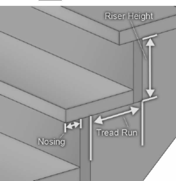

●
Stair style: Select "Straight" to draw classic stairs. Select "Ramp" to
draw a ramp
, instead.
●
Stair Height: This is the overall height of the stairs.
●
Stair Width: This is the overall width of the stairs.
●
Tread Run: This is the length of the tread, minus the tread nose.
●
Tread Nose: This is the length of the tread nose. The nose is the part of the tread that
overhangs the risers.
●
Rise: This is the overall height of a single step.
●
Tread Color: This is the color that is applied to the treads.
●
Include Risers: Check this box to include stair risers.
●
Riser Color: This is the color that is applied to the step risers (if present).
●
Include Railing: Check this box to include the railing when building stairs.
●
Rotation: This is the direction the stairs lead, measured in degrees clockwise from North.
To place stairs, select the stairs tool and hover the mouse over a floor or the ground. If the
location is valid, a preview of the stairs will be shown. Left click to place the stairs.
-Carriage Types:
-The stair carriage is the supporting element of the stair tread. DreamPlan allows the
following carriage types:
-None:
-
The support structure is not visible or the stairs are suspended.
-Closed Stringers:
-
The stairs are supported by stringers and the stringers are encased in a covering (such as
drywall).
●
Stringer Color: This is the color that is applied to the stringers.
-Open Stringers:
-The stairs are supported by one or more visible stringers.
●
Stringer Width: This is the thickness of each stringer.
●
Stringer Count: The number of stringers that will support the stairs.
-Knee Wall:
-The stairs are supported by and encased in a knee wall.
●
Wall Width: This is the thickness of walls on each side.
●
Wall Height: This is how tall each walls will be.
●
Build Left/Right/Back Wall: Which sides of the stairs to attach the walls.
●
Include Cap: Put an additional layer on the top of the walls.
●
Cap Width: This is the width of the additional layer.
●
Cap Height: This is the height of the additional layer.
●
Cap Style: This is the texture that is applied to the additional layer.
●
Cap Color: This is the color that is applied to the additional layer.
43

Tasks - Building Ramps
The
stairs tool
can also be used to draw a ramp. A ramp consists of the base, the slope, and
the landing.
-Ramp Width
-This is the overall width of the ramp.
-Ramp Height
-This is the height of the bottom of the landing. Or, the overall height, not including the
thickness of the ramp.
-Ramp Length
-This is the length of the ramp, not including the base or the landing.
-Base Length
-This is the length of the base of the ramp.
-Landing Length
-This is the length of the landing at the top of the ramp.
-Rotation
-This is the direction the ramp leads, measured in degrees clockwise from North.
-Ramp Slope
-This is the slope of the ramp, as determined by the ramp length and ramp height. The base
of the ramp may be sloped at a different angle.
To place a ramp, select the stairs tool, check the "ramp" radio button, and hover the mouse
over a floor or the ground. If the location is valid, a preview of the ramp will be shown. Left click
to place the ramp.
44

Tasks - Building Railings/Fences
This tool is for creating railings or fences. Railings and fences can only be placed on the
ground or on existing floors, decking, and stairs.
Anatomy of railings and fences:
R
ailing Posts:
The railing posts are the structural support elements of railings. DreamPlan
considers the railing rails to be part of the railing posts.
45
●
Rail Height: This is the height of the railing posts. Consult with local building codes on the
minimum height of railing in your jurisdiction.
●
Post (Width X Depth): This is the width and depth of the railing posts.
●
Post Spacing: This is the maximum distance between posts, measured from the center of
each post. Rail spacing is variable depending on the length of the span being created.
DreamPlan will generate enough posts to cover the span and will not exceed this setting,
although a smaller spacing value may be used to evenly space posts.
●
Post Style: This is the style that is applied to the railing posts and rail boards.
●
Post Color: This is the style that is applied to the railing posts and rail boards.
Railing Infill: The railing infill refers to the design elements between the railing posts and rails.
●
Infill Type: The type of infill applied to the railing.
Railing Cap: The railing cap refers to two parts of the railing. First, a decorative cap can be
placed on top of railing posts and can be used to contain deck lighting. Second, a board laid
horizontally across the railing rails is useful for placing plates, beverages and other items. Both
of these are optional.
●
Cap Type: This is the style of rail capping for the railing.
●
Rail Cap Width: This is the width of the rail cap board.
●
Cap Style: This is the style of the post cap (if selected).
Railings can be drawn in several different ways:
●
The Ground: Railings can be placed on open ground (terrain). To begin drawing a railing,
place the stylus over the desired spot and left-click. Move the stylus to where the railing
ends and left-click again. After a railing is complete, a new railing will automatically start
from the end of the last railing. To stop drawing the current railing and start a new railing,
press the Esc key.
●
Floors: Railings can be placed on interior floors in the same way that railings are placed on
terrain. The start and end points of the railing must be on the same floor.
●
Decking: Railings can be placed on deck flooring in the same way that railings are placed
on interior floors. The start and end points of the railing must be on the same deck. In
addition, the stylus will automatically snap to corners of the deck.
●
Stairs: Railings can be placed on stairs by hovering the mouse over the stairs. The railing
will be placed to the side of the stairs which is closer to the mouse.
46

Tasks - Building Exterior Paths
Exterior paths can be placed outdoors to represent things like flower beds, driveways and
sidewalks, patios, etc.
To begin placing exterior paths, click the Path button found on the
Exterior Tab
toolbar. Path
Style and Path Color will be displayed on the property panel. Style and Color are combined to
create a highly customizable path surface. Click on the Eyedropper button to change the style
or color.
After the style and color have been selected,
a path can be drawn.
After the path is created,
the path can be reshaped by dragging the path studs.
47
Tasks - Building a Pool
Pools can be built using the pool tool. After selecting the pool tool, a pool path can be drawn.
While drawing the pool path, holding down the Shift key will allow drawing diagonal pool
edges. Pressing the Esc key while drawing a pool will cancel the current pool path.
After the pool path is complete, the pool edges can be shaped using the pool studs. Note that
the pool path cannot self-intersect.
Properties: Various properties of pools can be set before creating a pool or if a pool is
selected.
●
Pool Depth: Represents how deep the pool is relative to the default ground height.
●
Wall Color/Style: This is the color and style of the walls of the pool tub.
●
Bottom Color/Style: This is the color and style of the bottom of the pool tub.
●
Coping Width: This is the width of the coping (the edge around the pool).
●
Coping Height: The is the height of the coping relative to the top of the pool tub.
●
Coping Color/Style: This is the color and style of the coping.
●
Water Elevation: Represents the height of the water relative to the default ground height.
●
Corner Style: This is the shape of the pool's corners.
48
Tasks - Painting Walls
Walls, roof walls, and knee walls can be painted quickly and easily. To start painting walls, click
the Paint button on the toolbar.
The property panel will display options for Wall Style and Wall Color. Style and Color are
combined to create a highly customizable wall surface. Click on the Eyedropper button to
change the style or color.
The size of the style texture can be scaled with the Texture Scale option.
After the desired style and color are set, click on the wall to change its texture. Note that walls
are two sided and different textures can be applied to each side of the wall.
Paint Regions (if available): Parts of walls can be painted with the Paint Region tool. To begin,
select the "Add Paint Region" option and select the texture and color. Regions of the wall can
be then painted by clicking on the wall to start the region. After the desired region is
highlighted, click to complete the region. Region colors and textures can be changed with the
paint tool or deleted with the "Remove Paint Region" option.
49
Tasks - Measuring Distances and Lengths
This tool would allow us to measure distance between two points. Measuring tool is available
on all view modes: 3D View, 2D Blueprint, and 2D Rendered.
Measuring points are orthogonal by default. To allow measurement between two points that
are diagonal, hold the SHIFT key while dragging the mouse.
Whenever a measurement point is set to a wall, it will snap to the wall with some offset
distance. To prevent snapping to a wall, press the
Ctrl key.
To terminate the current measurement operation, press the ESCAPE key. Once terminated,
measurement information, including measurement line and measurement label is removed
from the scene.
Switching to another operation would also terminate the current measurement operation.
50
Tasks - Placing Objects
A wide variety of objects can be placed in a scene, from flowers and trees to refrigerators and
stoves.
To begin placing objects, select the category of object to be placed:
-Exterior:
-
●
Plants: Flowers, grasses and trees.
●
Lighting: Exterior lighting objects.
●
Furniture: Furniture which is typically found outdoors.
●
Accessories: Accessories which are typically found outdoors.
●
Misc: Miscellaneous items which are typically found outdoors.
-Interior:
-
●
Cabinets: Cabinets, bookcases and shelving.
●
Furniture: Tables, chairs, bedding, etc.
●
Appliances: Major appliances, such as refrigerators and stoves.
●
Electronics: TVs, radios, computers.
●
Lighting: Indoor lamps and other lighting.
●
Plumbing: Sinks, showers and toilets.
●
Misc: Miscellaneous indoor items.
Each category will have a unique catalog of items associated with it. Select the desired item
from the catalog found on the property panel. Move the mouse over the scene to the desired
location and click the left mouse button. The item can be placed multiple times in this manner.
Note: Objects can only be placed on the story currently being edited.
Each object has its own rules on where it can be placed. For instance, a tree can only be
placed over the ground and curtains can only be placed on a wall.
-Properties:
-Each object has various properties which can be set before placing the object or while the
object is selected.
●
Height: Sets how tall the object is.
●
Width: Sets how wide the object is.
●
Depth: Sets how deep the object is.
●
Radius: Sets how big around the object is.
●
Rotation: Sets the orientation of the object in the scene.
-Materials:
-Each object is made of various materials or colors. Each material is listed in the material
panel and can be changed by clicking on the color picker icon.
-Lighting (if available):
-Some objects have lighting properties associated with them. Note that lighting is not
available on all systems.
●
Enable Light:
●
Color:
●
Intensity:
51
Tasks - Creating a New Story
Creating new stories is done through the New Story window. The window can be opened with
the "New Story..." button at the bottom of the story selection panel.
The New Story window contains fields for creating a new story:
●
Story Name: A name such as "Basement" or "3rd Floor" that identifies the purpose of the
story. Any name can be entered, however duplicate names are not allowed.
●
Wall Height: The height of the walls for the new story.
●
Elevation: The elevation for the new story. If the new story is to be below ground level,
such as a basement or garden level, enter a negative number for elevation.
Story Templates: A list of story templates is provided as an example of how to create stories.
The templates can be used as a base for the new story.
Attaching to a Story: A new story can be attached to an existing story to automatically adjust
the new story's elevation. The current stories is provided in a list to select from.
To attach the new story to a current story:
●
Select the story from the list to attach to the new story to.
●
Select the button "Add Above" or "Add Below" and the new story elevation will be
adjusted to match the selected story.
●
Select "NONE" in the list to detach the new story from any current story.
52
Tasks - Editing a Story
Editing stories is done through the Edit Story window. The window can be opened with the
"Edit" button at the bottom of the story selection panel.
The Edit Story window contains fields for editing story properties:
●
Story Name: A name such as "Basement" or "3rd Floor" that identifies the purpose of the
story. Any name can be entered, however duplicate names are not allowed.
●
Wall Height: The height of the walls for the story. The wall height cannot be changed if
there are currently any walls placed on the story.
●
Elevation: The elevation for the story. If the story is to be below ground level, such as a
basement or garden level, enter a negative number for elevation. The elevation cannot be
changed if there are any objects placed on the story.
53

Tasks - Importing 3D Models
DreamPlan allows for the import of additional 3rd party or user created 3D models through the
Import 3D Model wizard. Select "Import 3D Model..." from the File menu or the Add Content
button on the toolbar.
When the Import 3D Model wizard is first opening, it will prompt for a 3D
model file to import. The following file types are supported:
●
.3DS (3DStudio Max)
●
.STL (Stereo Lithography)
●
.PLY (Polygon File Format)
Preview Window: After a file has been successfully loaded, a preview of the model will be
shown in the preview window. The model can be rotated by holding the left or right mouse
button down on the preview and then moving the mouse. The model can be zoomed in or out
using the mouse wheel.
The preview window also displays the alignment of the model. The green line shows the Y-Axis
(up direction), the red line shows the X-Axis (front direction) and the blue line shows the Z-Axis
(left direction).
Use the "Load 3D Model..." button to load a different model.
-Model Properties:
-The following properties for an imported model can be set: -Display Name:
-
This is the name that will be displayed in the model category catalog. Each model must have a
unique display name within its category.
-Object Category:
-
This is the category that the model will be placed for selection. For instance, if the model is a
new door it could be placed in the "Building - Doors" category so it can be easily found.
-Object Type:
-
These are the rules that govern the model when placing it (Note: Doors and windows do not
have an object type and are always bound to walls):
●
Standard: The object has no special rules and will always be placed on the floor or ground.
●
Surface: The object, e.g. a table or counter, can have other objects placed on top of it. The
object will be placed on the floor or ground.
●
Floating: The object can be placed on top of Surface objects, e.g. a table. Otherwise, it will
be placed on the floor or ground.
●
Ceiling: The object will always be attached to the ceiling.
●
Wall: The object will always be attached to a wall.
-Rotation:
-The default rotation of the model. This is especially useful for door and window facings that
do not align with the X-Axis (the red line in the preview).
-Measurements:
-
The measurements are used to scale the model to the appropriate size. Entering one
measurement will scale the other measurements automatically. The unit inputs can be set to
small (millimeters or inches) or large (meters or feet) using the radio buttons.
Conversion Notes: The conversion notes show potential problems with importing the model,
including any issues that will prevent a model from being imported. It may be desirable or
necessary to edit the model with 3D editing software before importing the model.
See also:
Where can I download 3D models to import into DreamPlan?
54
Tasks - Exporting 3D Models
Use the Export 3D Model tool to export a 3D model of your house plan. The following file types
are supported:
●
.OBJ (Wavefront)
●
.STL (Stereo Lithography)
Select "Export 3D Model..." from the File menu. The Export Model dialog will open. For
exported 3D model, you can:
●
Include or exclude terrain, roofs, pools, exterior paths
●
Choose stories of your house plan
Enter the output folder name where the exported files will be placed (the project name is used
by default) and select the output folder location. Make sure that .obj or .stl is selected as the
output format and click "Export".
The OBJ file format is one of the most important file formats in
3D printing and 3D graphics applications. It is the preferred format for multi-color 3D printing
and is widely used as a neutral interchange format for non-animated 3D models in graphics
applications.
STL (binary representation) files describe only the surface geometry of a three-dimensional
object without any representation of color, texture or other common model attributes.
Your 3D model may be loaded into any 3D software that will open Wavefront OBJ or Stereo
Lithography STL files.
55

Tools - Tool Panel
The tool panel contains various tools that are used when editing a scene. It is located to the
right of the scene.
-
Select Mode On/Off:
-This button is to switch between drawing mode and select mode. When in select mode, this
arrow is displayed as green. In select mode, objects can be selected, edited and deleted.
-
Undo:
-This will undo the action taken in the project.
-
Redo:
-This will redo the last undo.
-
Delete:
-This will delete the currently selected object from the scene.
-
Copy:
-This will copy the currently selected object. This will also turn off select mode.
-
Walls On/Off:
-This will toggle the walls to display at their full height or lowered. Lowering the walls can
make it easier to draw interiors.
-
Roof On/Off:
-This will toggle the roof display.
-
Show scene objects On/Off:
-This will toggle the display of scene objects. Scene objects are those objects that are not
structural or permanent.
-
56

Change View:
-Clicking the View button will open a dialog to change the display mode of DreamPlan
between full 3D rendering, rendering as a 2D blueprint, or rendering as a 2D image.
-
Grid:
-This button will toggle the grid display.
-
Snap:
-This button will toggle terrain snapping on and off.
-
Guides:
-This button will toggle showing cursor guide lines when in 2D modes.
-
Show Navigation Controls On/Off:
-This button will toggle showing the navigation controls when the mouse is not hovering over
them. If turned off, the controls can still be accessed by hovering the mouse over the control
area.
-
Show Text Labels On/Off:
-This button will toggle display of text labels.
57
Tools - Text Labels
The Text Label tool allows you to add text to a project when it is viewed in 2D Blueprint or
Rendered mode.
Text labels come in two modes.
●
Generic: This is a blank label that can be placed anywhere in the project.
●
Room: This label is placed over a room. It will be positioned at the geometric center of the
room and will automatically include the room area in the label's text. After placement, the
room label will function like a normal text label. It will not be updated or removed if the room
changes.
Text Label: The text label you would like to insert. You can also edit it from the label on the
project.
58
-Font Attributes:
-
●
Style: The font to display the text label in.
●
Bold: The font will be bolded if this button is checked.
●
Italics: The font will be italicized if this button is checked.
●
Underline: The font will be underlined if this button is check.
●
Left Justify: The label's text will be left aligned.
●
Centered: The label's text will be centered within the label.
●
Right Justify: The label's text will be right aligned.
-Font Size:
-The size of the text in the label. The font size can be selected from the pull down list or a
custom size can be entered with the keyboard.
-Rotation:
-
The angle of rotation of the text label. You can use the rotate icons to snap the text label to 90,
180, 270 or 360°.
-View Label in:
-
●
Blueprint and Rendered: The label will be shown in both 2D Blueprint and 2D Rendered
view modes.
●
Blueprint only: The label will only be shown when the view mode is set to 2D Blueprint.
●
Rendered only: The label will only be shown when the view mode is set to 2D Rendered.
NOTE: Text labels are not shown in 3D view mode.
-Text Color:
-
The color of the text, per the view mode. Colors for 2D Blueprint and 2D Rendered can be
assigned independently.
-Text Label Use:
-
To place a text label, begin by selecting the Text Label tool on the Tools tab. Text labels can
only be placed while in 2D Blueprint or 2D Rendered view modes (Text labels are not available
in 3D view mode).
Click the desired location for the text label on the scene and the text label will be created and
selected. The text label can then be edited, moved, or have its attributes changed. To delete
the label, click the trash icon or delete button.
59
Tools - Add Symbols
The Add Symbols tool allows you to add architectural symbols to a project when it is viewed in
2D Blueprint.
Architectural symbols allows us to specify important information pertaining to locations of
common connections such as power outlets, telephone, cable. We can also specify location of
wi-fi, keypad, security camera, etc.
Currently, there are 14 symbols available:
1. Cable - cable connection symbol
2. Camera - security camera symbol
3. Exterior door - exterior door symbol
4. French door - French door symbol
5. Gas - gas tap symbol
6. High voltage outlet - high voltage outlet symbol
7. Interior door - interior door symbol
8. Internet - internet symbol
9. Keypad - keypad symbol
10. Oil - oil tap symbol
11. Sliding - sliding door symbol
12. Standard outlet - standard outlet symbol
13. Telephone - telephone connection symbol
14. Wifi - wifi symbol
-Symbol Properties
-
-Scale Attribute:
-The scale of a symbol with respect to its original size. Symbols may be resize from 25% up
to 300% of the original symbol size.
-Rotation Attribute:
-
The angle of rotation of a symbol. Symbols can be rotated from 0° to 360°.
-Color Attribute:
-
The color of the symbol. Symbol colors may be assigned by pre-defined and custom colors.
-Adding symbols:
-
Begin by selecting a symbol from the treeview and then moving the mouse cursor onto the
scene. Once the mouse cursor is positioned on the desired location click on the left mouse
button to add the symbol.
A symbol can be added consecutively into the scene without clicking on the symbol again from
the treeview. This can be performed by clicking on the left mouse button while holding the Shift
key. Releasing the Shift key will end the consecutive symbol add operation.
60
Tools - Picking Textures
The texture picker window is used to select the texture style to be applied to many objects,
such as walls, blocks and railings.
To select a texture, click the desired texture in the image list then click the "Select Texture"
button. The currently selected texture is shown in the preview window.
Import Texture: Use this button to import a custom texture into DreamPlan.
Remove Texture: Use this button to remove a custom texture from DreamPlan.
61
Tools - Paint Calculator
The Paint Calculator tool is used to quickly estimate the amount of paint needed to paint a
room.
To get started, select Paint Calculator from the Tools tab. Once the tool is selected, use the
mouse to highlight the room in the drawing to calculate.
After selecting a room, the Paint Calculator window will open with several options for
calculating the amount of paint needed. The selected room is previewed on the right panel.
●
Total Wall Area: The is the paint area of the wall which make up the room, with door and
window areas subtracted.
●
Include Ceiling: If checked, the ceiling is included in the final calculation for the amount of
paint.
●
Include Doors and Windows: If checked, the door and window area is included in the final
calculation for the amount of paint.
●
Total Paint Area: The sum of all selected paint surfaces.
●
Number of Coats: How many coats of paint will be applied in the paint calculation.
●
Square feet per gallon/Square meters per liter: How much surface area one gallon or liter is
expected to cover in one coat of paint. Paint manufacturers often provide this information
for their various products.
●
Total gallons/liters: The amount of paint needed to cover this room.
62

Tools - Trace Wizard
The Trace Wizard is used to set up an image for tracing. The image must be in PNG or JPG
format. Also PDF format is appropriate.
63

Tracing requires DreamPlan to be in 2D Blueprint rendering mode. DreamPlan will
automatically switch to 2D Blueprint mode when the Trace Wizard is started.
-Step 1: Loading the trace image
-
The first step in the Trace Wizard is selecting the image to trace over. Typically, images that
contain floor plans or lot layouts are used for the trace image. These can be obtained from
home builders, web searches or even scanned blueprints.
Generally, the larger an image is size (pixels) the easier it is to work with.
Click the Browse for file... button to select a trace image.
Choose the name of the Story from the drop down list that you would like to add a Trace
image and start the Trace wizard.
When the image is loaded and the correct story is selected, click the Next button to continue
with the Trace Wizard.
-Step 2: Calibrating the trace image
-
After the image is loaded, it must be calibrated to match DreamPlan. To do this, find a feature
(e.g. wall, property line, size graph) on the trace image with a known length.
To begin the calibration step, click the Start Calibration button. Click the starting point of the
feature on the trace image. A red calibration line will appear. Move the line to the end point of
the feature and click again.
After the end point is
selected, enter the length of the feature:
64

After a valid length is entered, the trace image will be
resized to match the scale used by DreamPlan. NOTE: The maximum size of a project is 328'
X 328' (100m X 100m).
Click the Finish button to complete the Trace Wizard.
Click the Cancel button to return the Start Trace Mode.
65

Tools - Searching Catalogs
The search tool can be used to find objects in the many catalogs found across DreamPlan.
To open the search window, click the "Search for Models..." button found under each of the
catalog lists for by pressing the F3 key. The search window is modeless, and you can continue
to work on your project while it is open.
The search window:
Search Keywords: Enter
one or more terms to search for. If the model name, category or catalog contains the search
term, the model will show up in the search results.
66
Search button:Click to start search for the entered keywords.
Search Results: A list of all models which meet the search criteria. Clicking on a model in the
list will activate the model for use.
Search Online: Conducts on online search with the website 3DArchive.net using the
keywords. NOTE: 3DArchive.net is not affiliated with NCH Software in any way.
Watch Import Model Tutorial: Opens the tutorial showing how to import 3D models into
DreamPlan.
67
Tools - Block Drawing Tool
The Block drawing tool allows the creation of custom shaped, colored and textured objects.
Blocks can be used to create surfaces not available with other tools such as counter tops,
landings, flower beds, etc. Other objects can be placed on top of or on the edges of Blocks.
To create a block, select the Block tool to start drawing a block path. Add as many points to the
path as needed. Closing the path will complete the block. While drawing the path, holding
down the shift key will allow diagonal edges. Pressing the ESC key will cancel the current path.
After the block is created, the block can be reshaped by dragging the path studs.
Properties:
●
Elevation: The elevation, as measured from the terrain to the bottom of the block.
●
Height: The height of the block, as measured from the bottom of the block.
●
Edge Style/Color: The style (texture) and color of the sides of the block.
●
Top Style/Color: The style and color of the top of the block.
●
Bottom Style/Color: The style and color of the bottom of the block.
●
Style Texture Scale: The size of the style texture of the block.
●
Rotation: The angle of the block in degrees, compared to when it was originally drawn.
68
Tools - Printing
The Print Preview window shows a preview of the image to be printed along with paper
settings.
●
Paper Size: Choose the paper size from a list of available U.S. and A paper sizes. Paper
dimensions will be shown in the units (Imperial or metric) which is currently being used by
the application.
●
Orientation: Sets the orientation of the print to Landscape (wide) or Portrait (tall).
●
Margins: Sets the region around the border of the paper which will not be printed on.
Represents both the left/right and top/bottom margins.
69
Screen References - Color Picker Dialog
Color Picker Dialog
The color picker is divided into multiple parts, with several ways available to choose a color:
Visually Adjusting Color
The top half of the dialog consists of 2 colored boxes, one that lets you pick any point in a
256 x 256 square and the other that works as a long slider. Which colors are displayed in
these two boxes depends on which radio button is selected (see below), but in all cases the
position of the slider will change the colors available in the square box. Which ever point is
selected in that square box is the selected color.
Adjusting by RGB or HSV
Underneath the square colored box, there is a series of 6 options (1 each for hue,
saturation, value, red, green, and blue) that each contains a radio button, a slider, and an
up-down number control. If one of the 3 HSV radio buttons is selected, that value will be
represented by the visual slider (see above) while the other two values will be the axes of
the square color box. The controls work the same way if one of the RGB radio buttons is
selected. You can also adjust these values with the sliders provided next to the labels, as
well as the up/down controls next to the sliders. Any adjustment of these values will update
the visual controls, and any adjustment of those visual controls will update these values.
Selected Color
The selected color is displayed to the right of the RGB and HSV controls. The box is split
diagonally, with the upper left section labeled New (the color you are creating), and the
bottom right section labeled Current (the color that already exists, and will continue to be
selected if you Cancel the dialog). Beneath that is the Hex Value of the selected color (you
can also enter any valid hex value there to update the selected color). There is an
eyedropper button to the right of the selected color that will allow you to set the selected
color by sampling anywhere on the desktop.
User-defined Color Palette
At the bottom of the dialog you will find a series of 12 colored rectangles alongside a button
titled Set to Swatch. These comprise the user-defined color palette, and allow you create
and save (these will persist even when DreamPlan is closed) your own custom colors. To
set a swatch's color, first select that swatch by clicking it. Then choose your desired color,
and finally click the Set to Swatch button. You can then load any of the saved colors by
simply clicking on that swatch.
70
Screen References - Send Email Dialog
Send An Email
The Send Email Dialog sends an email automatically. Email settings will need to be set up
before an email can be sent. If you have not already done so, you will be prompted for your
email settings before proceeding.
Email Options
-Send To
-Enter the email address(es) of the recipient(s). Put a comma between each email address.
-Subject
-Any text entered into this field will appear as the subject of the email.
-Body
-Any text entered into this box will appear as the body of the email.
-Footer
-Any text entered into this box will appear at the very end of the email. This may require a
purchase to enable changing it.
-Settings
-Clicking this button will open the Email Settings dialog window, where changes can be
made to the email server, sending address, etc.
71
Screen References - Sample Project Download
Dialog
The sample project download dialog appears when DreamPlan is downloading the sample
projects.
If you see that the sample project you want to open is marked complete, you can use the
Cancel button to skip downloading other projects. The download will resume next time you use
the "View/Load Sample Project" option.
72
Screen References - Create New Wall Type
Create New Wall Type:
Display Name: Enter the name that will be displayed in the wall list.
Wall Height: Enter the height of the walls when using this wall type.
Wall Width: Enter the width of the walls when using this wall type.
This wall type is used to create rooms: If checked, this wall type will create a room if it is
used to make an enclosed space with other walls.
73

Screen References - Screen Capture
Screen Capture:
A screen capture can be saved locally or shared online in a number of ways.
●
Save to Disk: This option will save the screen capture to a local disk, USB, or other
storage device attached to the computer.
●
Share on Flickr: This option will post the screen capture to a Flickr account (an active
account is required).
●
Save to Google Drive: This option will save the screen capture to a Google Drive account
(an active account is required).
●
Save to OneDrive: This option will save the screen capture to a OneDrive account (an
active Microsoft account is required).
●
Share on Twitter: This option will post the screen capture to a Twitter account (an active
account is required) as a tweet.
Note: For sharing screen captures on social media sites (Flickr, Twitter, etc.), an account must
be created prior to sharing. DreamPlan will prompt for the account user name and password
before sharing. Some social media platforms require DreamPlan be authorized access to the
account before sharing. Once an account has been authorized, DreamPlan will continue to use
that account without further authorization.
Reset Account Credentials: The option will allow resetting of credentials if they are incorrect,
no longer valid, or a different account is desired.
For more information on account authorization, see:
Flickr authorization
Google Drive authorization
74
Screen References - Import Texture
Custom textures can be imported into DreamPlan and used anywhere that packaged textures
are used. Textures can be found on many websites or can be hand made using a drawing
application.
DreamPlan can use PNG (.png) or JPEG (.jpg or .jpeg) images as textures.
To import a texture, click on the "Import Texture..." menu item found under the File tab. The
Import Texture dialog will open.
Import Texture Wizard:
●
Texture File: This is the image file that will be imported.
●
Display Name: This is the name that will be displayed in the Texture Picker dialogs.
●
Restrictions: Some video cards have more limited capabilities than other, such as the size
of textures that can be use. And restrictions on textures will be listed here.
●
Categories: This is a list of all of the individual categories that the texture will be imported
to. Multiple categories can be selected to use the texture.
Restrictions:
●
Texture Size: All video cards have a limit on the size (in pixels) of textures they can display.
Although newer video cards can display textures that are quite large, it is recommended
that texture be limited to under 1024x1024.
●
Power of 2: Some video cards require that texture sizes be in powers of 2. For instance,
the width and height must be 2, 4, 8, 16, 32, 64, etc. pixels. However, the height and width
may be different sizes.
●
Square: Some older video cards require that textures be square. This means the texture
width and height in pixels must be equal.
Hints for Textures:
Textures can be images of anything, but some images are better than others for producing
realistic rendering. Generally, the larger the texture the better the quality.
Textures applied to most surfaces are tiled (repeated) if they are not large enough to cover the
entire surface. Some textures are specifically made to be tiled so they look like a single texture.
If textures are not made to be tiled, seams will appear in the places where the tiling occurs.
When downloading textures from websites, look for textures that have a "Tileable" property.
75
Screen References - App Search Dialog
The App Search Dialog lets you search for various tools, models, and menu options in
DreamPlan. You can open the App Search Dialog (if available) by pressing
Ctrl + Shift + Q ,
or by clicking the searchbar in the upper right, typing a few letters of what you're searching for,
and clicking "See more results..."
Find Effect or Tool
Type a keyword you want to find or type a few letters of what you're searching for.
Search Button
Click the button to start searching.
Search Results
All related items to the search keyword will be displayed here. Sort the columns by clicking on
the column headers. Click an item to automatically use it and know where to access it.
Feature - Name of tool, model or menu option.
Location - Feature's location within DreamPlan.
●
Menu items have locations which look like "Menu - [submenus]". Click the menu button in
the top left and follow the listed submenus to find a menu item.
●
Tools have locations which look like "Toolbar - [tab]". Switch to the indicated tab at the top
of the screen to find a tool. Clicking a tool will switch to its tab and switch to the tool, unless
it is disabled.
●
Catalog items have locations which look like "Catalog - [tool] - [category]". Switch to the
indicated tool and expand the indicated category to find a catalog item. Clicking the result
will do all that and also select the item for placement.
76
Screen References - Options ~ General
Measurement Units: This option is used to set the dimension display as Imperial (US/UK) or
Metric.
When Metric is selected as Measurement Unit, options for Minor Unit will be enabled. There
are two options for minor unit -
Centimeter (cm) and Millimeter (mm).
77
Screen References - Options ~ Display
Display camera controls: This option will add a camera controller at the bottom-left side of
the screen.
Display Model Preview: This option will show a preview when browsing the model library.
Show on-screen tool instructions: This option will show hotkeys and information for the
current tool.
Show human figure on new project: Place human figure when creating a new project.
Display Shadows: Render shadows on the scene (if available). Disabling this option can
speed up rendering on older systems.
78
Screen References - Options ~ Terrain
Terrain Texture: This option is used to set the style of the terrain as either Grass or Cement
(concrete)
.
79
Screen References - Options ~ Social Media
Reset Credentials: This button will open a dialog which lets you unlink DreamPlan from your
social media accounts, if they are linked.
80
