
Department of Defense
Systems Engineering Plan (SEP)
Outline
Version 4.1
May 2023
Office of the Under Secretary of Defense for Research and Engineering
Washington, D.C.
Distribution Statement A. Approved for public release. Distribution is unlimited.

Department of Defense Systems Engineering Plan (SEP) Outline, Version 4.1
Please direct questions or comments to the Office of Primary Responsibility:
Office of the Under Secretary of Defense for Research and Engineering
3030 Defense Pentagon
Washington, DC 20301
https://www.cto.mil
Distribution Statement A. Approved for public release. Distribution is unlimited.
DOPSR Case # 23-S-1904

Approved by
Thomas W. Simms
Acting Principal Deputy Director for Systems Engineering and Architecture
Office of the Under Secretary of Defense for Research and Engineering
Department of Defense Systems Engineering Plan (SEP) Outline Change Record
Date Change Rationale
May 2023
Added section 3.2.7 on
corrosion prevention and
control.
Requested by Deputy’s Management
Action Group (DMAG) and required by
DoD Instruction 5000.88, Engineering
of Defense Systems.
iv
Preface
The Department of Defense (DoD) Office of the Under Secretary of Defense for Research and
Engineering (OUSD(R&E)) prepared this Systems Engineering Plan (SEP) Outline for DoD
acquisition programs to use in preparing their SEPs. In accordance with DoD Instruction (DoDI)
5000.88, Engineering of Defense Systems, the SEPs for Major Defense Acquisition Programs,
Acquisition Category (ACAT) II, and ACAT III programs will contain the content described in this
outline unless the SEP approval authority waives the requirement.
Although the outline indicates required SEP content, the format is not prescribed. The
Component may use this document as a template or establish a SEP template that includes the
required content.
Passages labeled Expectation: indicate activities or content that the SEP approval authority will
evaluate as part of their review in approving or not approving the SEP. For example,
Expectation: At the start of the program, PMs will prepare a SEP to manage systems
engineering activities in accordance with DoDI 5000.88, Engineering of Defense
Systems.
Expectations passages stating the program “will . . . ” indicate the expectation is grounded in
and required by policy. Expectations stating the program “should . . . ” indicate OUSD(R&E)
highly recommends the item as a best practice even if it is not explicitly required by DoD policy.

CLASSIFICATION
1
[Program Name]
SYSTEMS ENGINEERING PLAN (SEP)
[DATE]
Publishing Organization
Distribution Statements as Needed

CLASSIFICATION
2
Office of Primary Responsibility (OPR):
Name
Address
Email

CLASSIFICATION
Contents
3
Contents
1 Introduction ............................................................................................................................. 8
2 Program Technical Definition .................................................................................................. 9
2.1 Requirements Development .............................................................................................. 9
2.2 Architectures and Interface Control ................................................................................. 11
2.3 Specialty Engineering ..................................................................................................... 12
2.4 Modeling Strategy ........................................................................................................... 13
2.5 Design Considerations .................................................................................................... 13
2.6 Technical Certifications ................................................................................................... 17
3 Program Technical Management .......................................................................................... 18
3.1 Technical Planning .......................................................................................................... 18
Technical Schedule ................................................................................................ 18
3.1.1.1 Schedule Management ...................................................................................... 19
3.1.1.2 Family of Systems/System of Systems Management ........................................ 20
Maturity Assessment Planning ............................................................................... 22
Technical Structure and Organization .................................................................... 22
3.1.3.1 Work Breakdown Structure ................................................................................ 22
3.1.3.2 Government Program Office Organization ........................................................ 22
3.1.3.3 Program Office Technical Staffing Levels .......................................................... 23
3.1.3.4 Engineering Team Organization and Staffing .................................................... 26
3.2 Technical Tracking .......................................................................................................... 31
Technical Risk, Issue, and Opportunity Management ............................................ 31
Technical Performance Measures .......................................................................... 34
Reliability and Maintainability Engineering ............................................................. 39
3.2.3.1 Reliability and Maintainability Requirements and Engineering Activities ........... 39
3.2.3.2 Reliability Growth Planning ................................................................................ 40
Manufacturing and Quality Engineering ................................................................. 41
3.2.4.1 Manufacturing and Quality Requirements and Engineering Activities ............... 41
3.2.4.2 Manufacturing Maturity ...................................................................................... 42
Human Systems Integration ................................................................................... 42
System Safety ........................................................................................................ 43
Corrosion Prevention and Control .......................................................................... 45
Software Engineering ............................................................................................. 45
3.2.8.1 Software Engineering Overview ........................................................................ 45

CLASSIFICATION
Contents
4
3.2.8.2 Software Planning Phase .................................................................................. 46
3.2.8.3 Software Execution Phase ................................................................................. 47
3.2.8.4 Software Obsolescence ..................................................................................... 48
Technology Insertion and Refresh ......................................................................... 48
Configuration and Change Management ............................................................... 49
Technical Data Management ................................................................................. 51
System Security Engineering ................................................................................. 51
Technical Reviews, Audits and Activities ............................................................... 52
Appendix A – Acronyms .............................................................................................................. 54
Appendix B – Item Unique Identification Implementation Plan ................................................... 54
Appendix C – Agile and Development Security and Operations Software Development Metrics
54
Appendix D – Concept of Operations Description ...................................................................... 55
Appendix E – Digital Engineering Implementation Plan .............................................................. 56
References .................................................................................................................................. 58
Tables
Table 2.1-1 Requirements Traceability Matrix (mandatory) (sample) ......................................... 11
Table 2.5-1 Design Considerations (mandatory) (sample) ......................................................... 14
Table 2.6-1 Certification Requirements (mandatory) (sample) ................................................... 17
Table 3.1-1 Integrated Product Team Details (mandatory unless charters are submitted)
(sample) ................................................................................................................................ 28
Table 3.2-1 Technical Performance Measures (mandatory) (sample) ........................................ 36
Figures
Figure 2.1-1 Specification Tree Illustrating Requirements Decomposition and Technical
Baselines............................................................................................................................... 10
Figure 3.1-1 System Technical Schedule as of [Date] (mandatory) (sample) ............................ 19
Figure 3.1-2 System-of-Systems Schedule as of [Date] (mandatory) (sample) .......................... 21
Figure 3.1-3 Program Office Organization as of [Date] (mandatory) (sample) ........................... 23
Figure 3.1-4 Program Technical Staffing (mandatory) (sample) ................................................. 25
Figure 3.1-5 SEPM Budget (mandatory) (sample) ...................................................................... 26
Figure 3.1-6 IPT/WG Hierarchy (mandatory) (sample) ............................................................... 27
Figure 3.2-1 Risk Reporting Matrix as of [Date] (mandatory) (sample) ...................................... 32
Figure 3.2-2 Risk Burn-Down Plan as of [Date] (mandatory for high risks; others optional)
(sample) ................................................................................................................................ 33
Figure 3.2-3 Technical Performance Measure or Metric Graph (recommended) (sample) ........ 38
Figure 3.2-4 TPM Contingency Definitions ................................................................................. 39
Note: Additional tables and figures may be included at the Component or Program Manager’s
discretion.

CLASSIFICATION
5
[MANDATORY APPROVAL PAGE CONTENT]
PROGRAM NAME – ACAT LEVEL___
[ACQUISITION PATHWAY]
SYSTEMS ENGINEERING PLAN
VERSION ___
SUPPORTING ______DECISION
AND
SUPPORTING TRANSITION INTO______PHASE
[DATE]
*************************************************************************************
SEP APPROVAL AUTHORITY APPROVAL
______________________________________________
Approval Authority Name
Approval Authority Signature Block
__________________________
Date

CLASSIFICATION
6
SUBMITTED BY
__________________________
Name
Program Lead Systems Engineer
__________
Date
__________________________
Name
Program Manager
_________
Date
CONCURRENCE
__________________________
Name
Lead/Chief Systems Engineer
(System Center or Command)
__________
Date
__________________________
Name
Program Executive Officer or
Equivalent
_________
Date
COMPONENT APPROVAL
__________________________
Name
Title, Office
Component SEP Approval
Authority
__________
Date

CLASSIFICATION
1 Introduction
7
Expectation: The following expectations apply to the Systems Engineering Plan (SEP) as a
whole:
• The Lead Systems Engineer/Chief Engineer (LSE/CE), under the direction of the Program
Manager (PM), will prepare a SEP to manage the systems engineering (SE) activities
starting at Milestone A (Department of Defense Instruction (DoDI) 5000.88, Engineering of
Defense Systems). The SEP should be a “living,” “go-to” technical planning document and
should serve as the blueprint for the conduct, management, and control of the technical
aspects of the government’s program from concept to disposal.
• The SEP is a planning and management tool, specific to the program and tailored to meet
program needs. Although the SEP Outline employs terminology mainly applicable to DoDI
5000.02, Operation of the Adaptive Acquisition Framework (e.g., DoDI 5000.85, Major
Capability Acquisition), the principles and practices described herein should be applied, as
appropriate, to all DoD programs.
• The SEP defines the methods for implementing all system requirements having technical
content, technical staffing, and technical management.
• The SEP will include the engineering management approach to include technical baseline
management; requirements traceability; linkage to the system architecture; configuration
management (CM); risk, issue, and opportunity management; and technical trades and
evaluation criteria (DoDI 5000.88, Para 3.4.a.(3).(b, d and l)).
• The SEP should include a digital ecosystem implementation plan that addresses the DoD
Digital Engineering Strategy goals and defines six key digital engineering ecosystem
attributes: infrastructure, environment, data, security, collaboration, and innovation. Applied
elements of these attributes (requirements, models, digital artifacts, network
hardware/software tools, data accessibility, and compatibility, etc.) will be evident in the
planning of the digital ecosystem implementation that results in the authoritative source of
truth (ASoT) for the program (DoDI 5000.88, Para 3.4.a.(3).(m)).
• The SEP will describe a data management approach consistent with the DoD Data Strategy.
The approach should support maximizing the technical coherency of data as it is shared
across engineering disciplines (DoDI 5000.88, Para 3.4.a.(3).(s)). Additional approaches to
data management should at a minimum describe:
o The government’s ownership in, or intellectual property (IP) license rights it has acquired
to, data it created or a contractor delivered to it, respectively;
o Digital artifact generation for reporting and distribution purposes;
o Expected data and method of delivery to the government, from all models, simulations,
designs, reviews, audits, analysis, formal contract deliverables, and expected level of
data rights (DoDI 5000.88, Para 3.4.a.(3).(j)); and
o Sufficient data to support system testing and assessment of the system.
• Upon approval by the Milestone Decision Authority (MDA), the SEP provides authority and
empowers the LSE/CE to execute the program’s technical plan.
• The SEP should be updated following a technical review, before milestones or the
Development Request for Proposal (RFP) Release Decision Point, or as a result of SE
planning changes.

CLASSIFICATION
1 Introduction
8
• The SEP should be updated after contract award to reflect (1) the winning contractor(s)’
technical approach reflected in the Systems Engineering Management Plan (SEMP) and
(2) details not available before contract award. This post-award update should be
completed within 120 days of contract award or no later than 30 days before the next
technical review. The program should define and justify this update as either a minor or
major update as a way to influence related staffing and approval risk.
1 Introduction
The introduction should:
• Summarize the program (ensure the description aligns with the program Acquisition
Strategy (AS)).
• Describe how the Program Management Office (PMO) has tailored the SEP to execute
the AS.
• Describe the program’s plan to align the Prime Contractor’s SEMP with the PMO SEP.
• Summarize how and when the SEP is updated and the criteria for doing so.
• Identify the phase of the program, its entry and exit criteria, and approval and updating
authority(ies).

CLASSIFICATION
2 Program Technical Definition
9
2 Program Technical Definition
2.1 Requirements Development
Describe how technical requirements are defined, derived, and refined from the Joint
Capabilities Integration and Development System (JCIDS) or other applicable capability
requirements documents down to configuration item (CI) build-to specifications and verification
plans. (See SE Guidebook (2022), Requirements Analysis Process, for additional guidance).
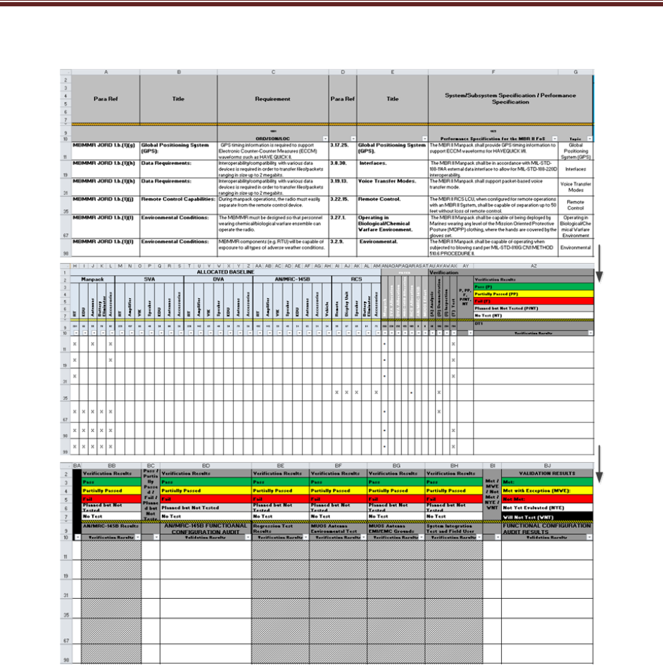
Expectation: Program should maximize traceability and the use of models as an integral part of
the mission, concept, and technical baseline to trace measures of effectiveness, measures of
performance, and all requirements throughout the life cycle from JCIDS (or equivalent
requirements authoritative source(s)) into a verification matrix, equivalent artifact, or tool that
provides contiguous requirements traceability digitally. A decomposition/specification tree
provides a summary of the requirements traceability and technical baselines. The requirements
trace should not contain any orphan requirements. The requirements trace should identify
those requirements that were identified in the JCIDS documents as expected to change over the
life of the program due to evolution of the threat or technology so that they may be considered in
the modular open systems approach (MOSA). Figure 2.1-1 shows a sample Requirements
Decomposition/Specification Tree/Baseline (DoDI 5000.88, Para 3.4.a.(3).(l)).
Expectation: Program requirements documents for all acquisition programs with digital
components and interoperability requirements will have program protection, cybersecurity, cyber
survivability, and operational resilience requirements defined in the requirements source (see
DoDI 5000.82, Acquisition of Information Technology (IT)). Cybersecurity requirements are
usually related to the Risk Management Framework (DoDI 8510.01, Risk Management
Framework for DoDEA Information Technology) and federal laws. Cyber survivability
requirements are specified using the Joint Staff Cyber Survivability Endorsement
Implementation Guide and are threshold requirements in addition to the System Survivability
(SS) Key Performance Parameter (KPP), even if the program does not have an SS KPP.
Operational resilience is a specified requirement in the DoDI 8500.01. Implied and derived
cyber requirements (security, survivability, resilience) should be considered if the requirements
source is lacking these cyber requirements, as all digital acquisitions are susceptible to some
cyber threats. Traceability and models should trace the cyber requirements through
decomposition as with all other requirements.
Expectation: System safety engineering principles and analyses are part of all requirements
development. Brief justification should be provided if system safety engineering principles and
analyses are not part of a requirement.

CLASSIFICATION
2 Program Technical Definition
10
CLASSIFICATION
Source: Name Year if applicable. CLASSIFICATION
Figure 2.1-1 Specification Tree Illustrating Requirements Decomposition and Technical Baselines
(mandatory) (sample)
Expectation: Program should trace all requirements from the highest level (JCIDS or equivalent
requirements sources) to the lowest level (e.g., component specification or user story). This
traceability should be captured and maintained in digital requirements management tools or
within model(s). The system Requirements Traceability Matrix (RTM) should be a model output
that can be embedded in or attached to the SEP, or the SEP should contain a tool reference
location. This matrix will grow as the system matures. The matrix should include the
verification method for each of the identified requirements and an indication whether each
requirement is expected to change over the life of the program. Table 2.1-1 shows a sample
RTM. If applicable, provide a link to a location where the current RTM is maintained that will
meet the expectation for requirements traceability.
Expectation: Program cyber requirements trace should also flow to the lowest level (e.g.,
component specification for passive sensing or user story for software automated resilience
approaches). Use early and repeated or updated Mission-Based Cyber Risk Assessments
(MBCRAs) supported by cyber test representatives (contractor and government) to inform cyber
requirement flow down.
CLASSIFICATION
2 Program Technical Definition
11
Table 2.1-1 Requirements Traceability Matrix (mandatory) (sample)
Source: Name Year if applicable. Classification: UNCLASSIFIED.
2.2 Architectures and Interface Control
Describe the architecture products, including the mandatory JCIDS architecture artifacts and
any additional architecture views or diagrams, the program will develop. Explain how those
mandatory architecture artifacts and additional architecture products are related to requirements
definition or how they support other SE activities. (See SE Guidebook (2022), Architecture
Design Process, for additional guidance).
The LSE should have all interfaces (including temporary interfaces related to mission
requirements) and dependencies clearly identified and accounted for in functional and physical
architectures (including but not limited to mechanical, electrical, thermal, data, control,
procedural, and other interactions). (See SE Guidebook (2022), Interface Management Process,
for additional guidance). Include as appropriate the following:
• List of the program’s planned suite of architecture products with status of each.

CLASSIFICATION
2 Program Technical Definition
12
• Architecture diagrams and models (e.g., physical, functional, behavior model and software).
• All hardware-defined modular system interfaces that define shared boundaries between the
major system platform and major system components, modular systems, or both, residing
within that platform; or between those major system components, modular systems, or both,
and between major system platforms (e.g., Interface Control Documents (ICDs), Interface
Requirements Specification (IRS), Interface Design Description (IDD), and functional
descriptions of software-defined interfaces conveying semantic meaning of interface
elements (e.g., the function of a given interface field)).
• All software-defined modular system interfaces that define interface syntax and properties
specifically governing how values are validly passed and received between major
subsystems and components in machine-readable format and a machine-readable definition
of the relationship among the delivered interface and existing common standards or
interface repositories (e.g., Application Program Interfaces (APL), Dynamic Link Libraries
(DLL).
• The contractor’s Software Architecture Description.
• List of major external system (outside the authority/control of the program) interfaces (attach
or embed separate ICD).
• List of modular system interfaces with the interface requirement specifications necessary for
system operation, interface standards and standards profiles, and other documentation that
fully describe the physical and functional interfaces needed to ensure compatibility between
interfacing components, systems, and platforms.
• List and reference of all program Component-specific, joint, and coalition mission threads
(JMT and CMT). (Department of Defense Acquisition Framework (DoDAF CV-6 (Capability
to Operational Activities Mapping) provides list of JMTs).
• Consistent with the program's acquisition strategy and Life Cycle Sustainment Plan, the
level(s) of indenture of the WBS (see section 3.1.3.1) and Software Architecture Description
(see section 3.2.3.2) for specific modular systems and major system components into which
functionality will be partitioned in discrete, cohesive, and self-contained units.
Expectation: Architectures are generated to describe and understand the system and how the
subsystems join together, including internal and external interfaces (e.g. human-machine
interactions, role-based access), to form the system and also to inform interoperability and
cyber testing.
2.3 Specialty Engineering
Provide a summary of the program approach for the integration of Specialty Engineering (SpE)
disciplines (e.g., Reliability and Maintainability, Manufacturing and Quality, Human Systems
Integration (HSI), and System Safety) throughout systems engineering planning (e.g.,
requirements, schedule, staffing, Technical Performance Measures (TPMs), and technical
reviews and activities) (DoDI 5000.88, Para 3.4.a.(3).(t)). Summarize critical elements of the
SpE sections in 3.2. Technical Tracking. As part of the program’s digital engineering approach,
describe how models, simulations, the digital ecosystem, and digital artifacts will be used as
part of an integrated approach to supporting SpE activities and deliverables. (See
https://ac.cto.mil/specialty-engineering/).

CLASSIFICATION
2 Program Technical Definition
13
2.4 Modeling Strategy
Define the modeling strategy to be used (model-supported, model-integrated, or model-centric).
Describe why the modeling strategy was chosen. Describe basic model components. The
modeling strategy may be included in the Digital Engineering Implementation Plan (See
Appendix E).
2.5 Design Considerations
As shown in Table 2.5-1, identify the design considerations that are critical to achieving the
program’s technical requirements. Ensure the design and architectural factors from DoDI
5000.88 are addressed. If additional documentation is required, those documents may need to
be embedded/attached in the SEP or located within the program’s digital ecosystem. (See SE
Guidebook (2022), Design Considerations, for a partial list of design considerations.) Not all are
equally relevant or critical to a given program, but all should be examined for relevance.
CLASSIFICATION
2 Program Technical Definition
14
Table 2.5-1 Design Considerations (mandatory) (sample)
Mapping Key Design Considerations into Contracts
Name (Reference)
Cognizant
PMO
Org
Certification
Documentation
(embedded or
reference
attached)
Contractual
Requirements
(CDRL #)
Describe how the program captures,
integrates, and uses technology, models,
simulations and data to support life cycle
activities within a digital ecosystem
Chemical, Biological,
Radiological, and Nuclear
(CBRN) Survivability
Describe how the design incorporates the
CBRN survivability requirements and how
progress toward these requirements is tracked
and documented over the life cycle.
For additional information on CBRN
Survivability, see
https://www.dodtechipedia.mil/dodwiki/display/t
echipedia/Chemical%2C+Biological%2C+Radi
ological%2C+and+Nuclear+Survivability
(Defense Technical Information Center (DTIC)
account required).
Modular Open Systems
Approach (MOSA)
List of applicable
MOSA/Interface
Standards and
Reference
Architectures |
Describe how the program uses MOSA in the
system design to enable affordable change,
evolutionary acquisition, and interoperability.
Describe how the system design considers the
evolution of requirements identified in the
capability documents. Describe how the
architectural design accommodates the
requirements. Provide rationale if MOSA is not
feasible or cost-effective. List known key
interfaces (with identification of spec),
known/desired severable modules and modular
system interfaces. Name MOSA-related
controlling or guiding reference architectures
and standards.
Digital Ecosystem Describe how the program uses the digital
ecosystem in the system’s design of life cycle
activities to establish system performance
validation capability through models,
simulations, or digital twin instantiations.
Describe how the digital ecosystem will be
maintained through the sustainment phase of

CLASSIFICATION
2 Program Technical Definition
15
Mapping Key Design Considerations into Contracts
Name (Reference)
Cognizant
PMO
Org
Certification
Documentation
(embedded or
reference
attached)
Contractual
Requirements
(CDRL #)
Describe how the program captures,
integrates, and uses technology, models,
simulations and data to support life cycle
activities within a digital ecosystem
the system to facilitate enhancements,
updates, and changes.
Describe how the digital ecosystem or parts of
it will be required to stay updated and
maintained in order to support quick software
updates and fast delivery to the field. Identify
design considerations that (i) leverage the
digital engineering implementation and digital
representations of design products (e.g., digital
threads, digital twin) and (ii) the program plans
to use to support development activities,
manufacturing activities, operations, and
sustainment activities.
System Security
Engineering
Program
Protection Plan
(PPP)
Describe how the design addresses protection,
survivability, and resilience of DoD warfighting
capability from foreign intelligence collection;
from hardware (HW), software (SW), and
firmware (FW) vulnerabilities, cyberspace
attacks, cyber events, and supply chain
exploitation; and from battlefield loss
throughout the system life cycle, balancing
security requirements, designs, testing,
sustainment activities, and risk management in
the respective trade spaces.
Diminishing
Manufacturing Sources
and Material Shortages
(DMSMS)
DMSMS
Management
Contract
Language
Describe how the design seeks to exhibit
DMSMS resiliency by both minimizing the
occurrence of obsolescence and enabling
quicker, lower cost resolutions when
obsolescence does occur. Describe how the
design is adapted to meet any contract
requirement so the product will have no
DMSMS issues for a specified period of time.
Describe how the part selection process avoids
items with projected near-term obsolescence.

CLASSIFICATION
2 Program Technical Definition
16
Mapping Key Design Considerations into Contracts
Name (Reference)
Cognizant
PMO
Org
Certification
Documentation
(embedded or
reference
attached)
Contractual
Requirements
(CDRL #)
Describe how the program captures,
integrates, and uses technology, models,
simulations and data to support life cycle
activities within a digital ecosystem
Describe how the program is conducting
monitoring and surveillance to identify issues
as early as possible as well as the processes
the program uses to mitigate those issues by
changing the design before production.
Parts Management Parts
Management
Contract
language
Describe how the program implements
contracts for standardization and parts
management to reduce the costly proliferation
of parts and equipment; enhance reliability,
availability and maintainability; and mitigate
counterfeit and DMSMS occurrences in
support of life cycle management and
sustainability through integrated program
planning and systems engineering throughout
the acquisition life cycle.
Intelligence
Life-Cycle
Mission Data
Plan (LMDP)
(MS A, Dev RFP
Rel, B, & C)
(if program is
Intelligence
Mission Data
(IMD)
dependent)
Validated Online
Lifecycle Threat
(VOLT) Report
Summarize the plans to identify IMD
requirements and need dates. Describe how
the program plans to address the risk of
unavailable IMD. Also, describe how the
design will address current and future threat
capabilities, specifically highlighting what will
be done to manage risk to system performance
in the event of a Critical Intelligence Parameter
(CIP) breach.

CLASSIFICATION
2 Program Technical Definition
17
Expectation: SEP demonstrates necessary design considerations as an integral part of the
design decision process, including trade study criteria.
2.6 Technical Certifications
Summarize in table format (Table 2.6-1) the system-level technical certifications obtained during
the program’s life cycle. Review the following references and add and delete certifications
to/from table 2.6-1 as applicable to your program. (See AFPAM 63-128, Attachment 14, AFI 63-
101/20-101, para 5.1.5).
Table 2.6-1 Certification Requirements (mandatory) (sample)
Certification
PMO
Team/POC
Activities to Obtain
Certification
1
Certification
Authority
Expected
Certification
Date
Airworthiness Airframe
Integrated
Product Team
(IPT)
?Q FY?
Joint
Interoperability
Test Command
(JITC)
Systems
Engineering
Integration and
Test (SEIT)
Operational test demonstrates
the system:
• Is able to support military
operations
• Is able to be entered and
managed on the network
• Effectively exchanges
information
JITC system
interoperabilit
y test
certification
memorandu
m
?Q FY?
Joint Weapons
Safety Working
Group
Any weapon or laser systems
used by two or more DoD
components must be reviewed
by the JWSWG
Weapon System
Explosives
Safety Review
Board
(WSESRB)
SEIT ?Q FY?
Transportability
?Q FY?
Insensitive
Munitions (IM)
Manufacturing
IPT
Reference Document: Program
Executive Office (PEO) IM
Strategic Plan
?Q FY?
Etc. ?Q FY?
1
Note: This entry should be specific, such as a specification compliance matrix; test, inspection,
or analysis; or a combination. It can also reference a document such as the Test and
Evaluation Master Plan (TEMP) for more information.
Expectation: Program should include the plans for required technical certification activities and
timing in the program Integrated Master Plan (IMP) and the Integrated Master Schedule (IMS).

CLASSIFICATION
3 Program Technical Management
18
3 Program Technical Management
3.1 Technical Planning
Technical Schedule
• List scheduling/planning assumptions and describe schedule risk assessment methodology
and frequency ((DoDI 5000.88, Para 3.4.a.(3).(e)).
• Describe how the IMP is maintained, where it is stored, and how to obtain access to it.
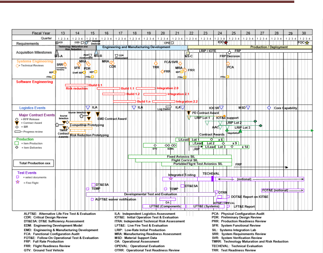
• Provide the current technical schedule derived from the IMP/IMS (Figure 3.1-1) for the
program, including activities/tasks and event milestones such as:
o SE technical reviews and audits
o Program protection activities
o Technology on/off-ramps
o RFP release dates
o SW builds/releases
o Minimum Viable Product
(MVP)/Minimum Viable Capability
Release (MVCR)
o Hardware/Software (HW/SW)
Integration phases
o Contract award (including bridge
contracts)
o Testing events/phases
o System-level certifications
o Technology Readiness
Assessments (TRAs)
o Manufacturing Readiness
Assessments (MRAs)
o Logistics/sustainment events
o System Diminishing Manufacturing
Sources and Material Shortages
(DMSMS) health assessments
o Long-lead or advanced
procurements
o Technology development efforts to
include prototyping
o Production lot/phases
o Need dates for government-
furnished equipment (GFE)
deliveries
o HSI domain and management
activities (e.g., HSI Plan, task
analysis)
o Production Readiness Reviews
(PRRs)
o Independent Technical Risk
Assessments (ITRAs)
o Developmental Test and Evaluation
Sufficiency Assessments
o Reliability growth testing
o Key modeling activities
o Model release dates
CLASSIFICATION
3 Program Technical Management
19
Source: Name Year [if applicable]. Classification: UNCLASSIFIED.
Figure 3.1-1 System Technical Schedule as of [Date] (mandatory) (sample)
Expectation: Program should properly phase activities and key events (competitive and risk
reduction prototyping, TRA, Preliminary Design Review (PDR), Critical Design Review (CDR),
etc.) to ensure a strong basis for financial commitments. Program schedules are event driven
and reflect adequate time for SE, integration, test, corrective actions, and contingencies. SEPs
for approval should include a current schedule, no more than 3 months old.
3.1.1.1 Schedule Management
• Provide a description of the program’s IMP and IMS process, to include definitions, updated
schedules, audits, baseline control, and the integration between program-level and
contractor detailed schedules (DoDI 5000.88, Para 3.4.a.(3).(f)).
• Provide the program-level IMP as an attachment to the SEP.
• Discuss the relationship of the program’s IMP to the contractor(s) IMS, how they are
linked/interfaced, and what the primary data elements are.

CLASSIFICATION
3 Program Technical Management
20
• Identify who or what team (e.g., Integrated Product Team/Working Group (IPT/WG)) is
responsible for developing the IMP, when it is required, and whether it is a part of the
contract.
• Describe how identified technical risks are incorporated and tracked into the program’s IMP,
IMS, and digital ecosystem.
• If used, discuss how the program uses Earned Value Management (EVM) cost reporting to
track/monitor the status of IMS execution and performance to plan.
• If EVM is not used, state how often and discuss how the IMS is tracked according to
contract requirements and how performance is tracked to budget.
• Summarize the program’s planned schedule risk analysis (SRA) products. Describe how
each product will help determine the level of risk associated with various tasks, determine
the readiness for technical reviews, and inform acquisition decisions. Identify who will
perform SRAs, methodologies used, and periodicity.
• Discuss how often the program conducts Defense Contract Management Agency (DCMA)
14-point schedule health checks on the IMS (Earned Value Management System (EVMS)
Program Analysis Pamphlet (PAP) (DCMA-EA PAM 200.1) October 2012:
http://www.dcma.mil/LinkClick.aspx?fileticket=0CBjAarXWZA%3d&portalid=31).
• Describe the process to resolve/correct deficiencies identified by the DCMA health check.
• Describe the impact of schedule constraints and dependencies.
• Describe initiated, completed, or planned actions to mitigate schedule drivers.
• Describe the periodicity for performing critical path analysis, identifying items on the critical
path with any risks and mitigations to meet schedule objectives.
• Describe how the PM will substantiate HW/SW schedule realism and the rigorous basis of
estimate used to develop the detailed hardware/software activities.
Expectation: Program should regularly check IMS health and conduct SRAs to inform program
decisions.
3.1.1.2 Family of Systems/System of Systems Management
As part of the digital ecosystem implementation and within the ecosystem, describe the external
organization integration plan. Identify the organization responsible for coordinating SE and
ecosystem integration efforts associated with FoS/SoS and its authority to reallocate resources
(funding and manpower). Describe methods used to document, facilitate, and manage
interaction among SE team(s) and external-to-program government organizations (e.g.,
OUSD(R&E) on technical tasks, activities, and responsibilities (e.g., requirements, technical
baselines, and technical reviews). Address the following:
• Resolution of issues that cross PM, PEO, and Component lines
• Digital engineering implementation and how it interfaces with new starts and legacy
programs. Include how the digital ecosystem will be implemented to track and highlight
integration issues within the program and with other programs (SoS)
• ICDs and any interface control WGs (ICWGs)

CLASSIFICATION
3 Program Technical Management
21
• “Triggers” that require a FoS/SoS member to inform the others if there is a cost, schedule, or
performance deviation
• Description of who or what team (e.g., IPT/WG) is responsible for maintaining the alignment
of the IMP and IMS across the interdependent programs
• Planned linkage between HW and SW upgrade programs within the FoS/SoS, to include
modeling
• Any required GFE/government-furnished property/information (GFP/GFI) (e.g., test ranges,
integration laboratories, and special equipment)
• Any major system components and modular system interfaces shared from or used by other
programs (MOSA)
Include an SoS schedule (Figure 3.1-2) that shows FoS/SoS dependencies such as alignment
of technical reviews, major milestones, test phases, GFE/GFP/GFI, etc.
Note: If the system neither has nor will have any relationship with any external organization, the
program may omit the content of 3.1.1.2 FoS/SoS Management and the associated Figure 3.1-
2 SoS Schedule.
Source: Name Year if applicable. Classification: UNCLASSIFIED.
Figure 3.1-2 System-of-Systems Schedule as of [Date] (mandatory) (sample)
Expectation: Program should
• Manage the internal program schedule and synchronize it with external program schedules.

CLASSIFICATION
3 Program Technical Management
22
• Identify external interfaces and clearly define dependencies. This information should
include interface control specifications or documents, which should be confirmed early on
and placed under strict configuration control. Compatibility with other interfacing systems
and common architectures should be maintained throughout the development/design
process.
• Identify any major system components, major system platforms, and modular system
interfaces (MOSA) with dependencies clearly defined (DoDI 5000.88, Para 3.4.a.(3).(r)).
This description should include all technical data and computer software (see Section 3.2.9)
that will be delivered with appropriate IP rights.
• Develop Memorandums of Agreement with interfacing organizations that include:
o Tripwires and notification to FoS/SoS members of any significant (nominally >10%)
variance in cost, schedule, or performance
o Mechanisms for FoS/SoS members to comment on proposed interface changes to
include program’s digital engineering implementation
o Fast-track issue identification and resolution process
Maturity Assessment Planning
Identify how the program will assess and document the technology maturity of all critical
technologies and manufacturing processes consistent with the USD(R&E) guidance for
technology readiness and Manufacturing Readiness Level (MRL) assessments. Identify the test
results, including any early cyber testing and artifacts that have been conducted or are planned,
that provide the documentation of the technology and manufacturing process maturity.
Expectation: Programs will develop all critical technologies consistent with the USD(R&E)
guidance for assessing technology readiness and MRL and document the maturity of those
critical technologies and manufacturing processes. This documentation will be made available
to support Office of the Secretary of Defense (OSD)- and Service-conducted reviews and
assessments.
Technical Structure and Organization
3.1.3.1 Work Breakdown Structure
If a WBS exists, embed or attach it to the SEP. In addition, provide:
• WBS dictionary that is traceable from the IMS
• Explanation of the traceability between the system’s technical requirements and the WBS
• (Optional) A digital ecosystem support IPT that is resourced or is part of the SEIT IPT or
LSE/CE
3.1.3.2 Government Program Office Organization
Provide the planned program office organizational structure (i.e., wiring diagram to illustrate
hierarchy and identify any positions that are not filled) with an as-of date, and include the
following elements (Figure 3.1-3):
• Organization to which the program office reports

CLASSIFICATION
3 Program Technical Management
23
• PM
• LSE/CE
• Functional Leads (e.g., test and evaluation (T&E), logistics, DMSMS, risk, production/quality,
reliability, SW, digital ecosystem, system safety).
FFRDC: Federally Funded Research and Development Center; KLP: Key Leadership Position
Source: Name Year if applicable. Classification: UNCLASSIFIED.
Figure 3.1-3 Program Office Organization as of [Date] (mandatory) (sample)
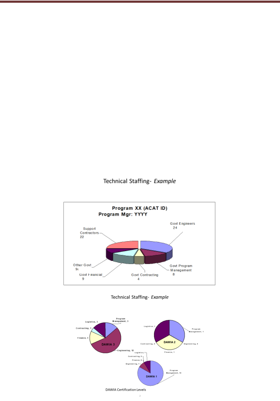
3.1.3.3 Program Office Technical Staffing Levels
Summarize the program’s technical staffing plan, to include:
• Risks and increased demands on existing resources if staffing requirements are not met
• A figure (e.g., sand chart, Figure 3.1-4) to show the number of required PMO full-time
equivalent (FTE) positions (e.g., organic, matrix support, and contractor support) over time,
by key program events (e.g., milestones and technical reviews)
• Description of the basis of estimate for the staffing sand chart
• A figure to show the program’s budget for SE and program management (SEPM) over time
as a percentage of total program budget (Figure 3.1-5)
• Description of the adequacy of SW development staffing resources
CLASSIFICATION
3 Program Technical Management
24
o
Describe the key PMO and contractor SWE position experience and qualification
requirements (e.g., quantity and experience level).
• Description of the adequacy of staffing resources for the digital ecosystem
o Describe the key digital ecosystem position experience to include the skill set,
experience and qualification requirements applicable for model-based systems
engineering, simulation, software engineering (SWE), and information technology
positions (e.g., quantity and experience level).
• For programs still under competition, the approaches used to manage flow of information in
the competitive environment
• Description of the adequacy of cyber engineering development staffing resources
o The key PMO and contractor cyber engineering position experience and qualification
requirements (e.g., quantity and experience level), to include adversarial testing
• Description of the adequacy of system safety staffing resources
Expectation: Program should use a workload analysis tool to determine the adequate level of
staffing, appropriate skill mix, and required amount of experience to properly staff, manage, and
execute successfully.

CLASSIFICATION
3 Program Technical Management
25
Source: Name Year if applicable. Classification: UNCLASSIFIED.
Figure 3.1-4 Program Technical Staffing (mandatory) (sample)

CLASSIFICATION
3 Program Technical Management
26
Source: Name Year if applicable. Classification: UNCLASSIFIED.
Figure 3.1-5 SEPM Budget (mandatory) (sample)
3.1.3.4 Engineering Team Organization and Staffing
• Integrated Product Team (IPT) Organization – Provide diagrams that show the
government and contractor (when available) IPTs and their associated working-level IPTs
(WIPTs) and WGs that illustrate the hierarchy and relationship among them (Figure 3.1-6).
Identify the government leadership for all teams.
• IPT Details – For government and contractor(s) (when available) IPTs and other key teams
(e.g., Level 1 and 2 IPTs and WGs), include the following details either by attaching
approved charters or in a table (Table 3.1-1, mandatory unless charters attached):
o IPT name
o Functional team membership (to include external program members, and representation
from all SpE disciplines (Section 2.3) and design consideration areas (Section 2.4))
o IPT roles, responsibilities, and authorities
o WBS tasks assigned to IPT
o IPT products (e.g., updated baselines, risks, etc.)
o IPT-specific TPMs and other metrics.

CLASSIFICATION
3 Program Technical Management
27
Source: Name Year if applicable. Classification: UNCLASSIFIED.
Figure 3.1-6 IPT/WG Hierarchy (mandatory) (sample)
Expectation: Program should integrate SE activities with all appropriate functional and
stakeholder organizations within the digital ecosystem. In addition, IPTs should include
personnel responsible for each of the design consideration areas in Table 2.5-1. Note: Ensure
the IPTs in Figure 3.1-6 match the IPTs in Table 3.1-1.
Systems
Engineering IPT
Digital
Engineering WG
Air Vehicle IPT
Airframe WG
Propulsion WG
Software WG
Security WG
Airworthiness
WG
E3 WG
Flight Systems
WG
T&E IPT
Live Fire WG
Survivability
WG
Interoperabity
WG
R&M WG
Mission
Equipment IPT
CNS/ATM
Mission
Planning
Defensive
Systems WG
Cyber WG

CLASSIFICATION
3 Program Technical Management
28
Table 3.1-1 Integrated Product Team Details (mandatory unless charters are submitted) (sample)
Team
Name
Chair
Team Membership
(by Function or Organization)
Team Role, Responsibility, and Authority
Products and
Metrics
SE IPT Lead SE
• Program Office
o Platform Lead
o Mission Equipment Lead
o Weapons Lead
o Test Lead
o Logistics Manager
o DMSMS Lead
o SW Lead
o Production/Quality Manager
o System Safety Lead
o Interoperability Lead
o R&M Lead
o System Security Engineering Lead
o Cyber Lead
• PEO and PM
• Service Representative
• OSD SE
• Key Subcontractor or Suppliers
• External programs
• Digital Ecosystem Lead
• Intelligence Lead
• Environmental Lead
• DCMA Engineers
Role: IPT Purpose (e.g., Aircraft Design and Development)
Responsibilities: Integrate all technical efforts throughout
the life cycle within an end-to-end digital ecosystem
• Manage and oversee design activities
• Oversee configuration management of requirements and
their traceability
• System Safety
• Manage specialty engineering activities including the
following disciplines: survivability/vulnerability, human
systems, integration, electromagnetic environmental
effects (E3), reliability and maintainability (including
availability), system security, and environmental impacts
to system/subsystem performance
• Evaluate and mitigate counterfeit and DMSMS risk in
design, production, and sustainment
• Manage safety and certification requirements
• Ensure compliance with applicable international, federal,
state, and local environment, safety, and occupational
health (ESOH) laws, regulations, and treaties
• Manage system manufacturing assessments, weight,
and facilities management (System Integration
Laboratory) planning
• Perform functional allocations and translate the system
definition into WBS
• Ensure compliance with all specialty engineering
specification requirements
• Support the Program Protection IPT and Program
Protection System Engineering
• Manage SEIT performance through digital ecosystem,
EVMS, TPMs, and other metrics and risk assessments
Products:
SEP/SEP
updates
WBS, IMP/IMS
input
Specifications
Digital
Ecosystem
Architecture and
Design
Description
Metrics tracked
by IPT:
• Cost
• Performance
• Schedule
• Engineering
Infrastructure
and
Environment
Utilization and
Performance
Metrics

CLASSIFICATION
3 Program Technical Management
29
Team
Name
Chair
Team Membership
(by Function or Organization)
Team Role, Responsibility, and Authority
Products and
Metrics
• Identify and communicate SEIT issues to leadership
• Evaluate technical and performance content and
cost/schedule impacts to support the Configuration
Control Board (CCB) process
• Support test plan development and execution
• Support the T&E IPT in system verification requirements
• Support the Product Support IPT WGs and other
Technical Interchange Meetings (TIMs)
• Develop and support the SEIT part of the incremental
development and technology refresh processes
• Support Program Management Reviews (PMRs)
• Support program technical reviews and audits
• Perform SEIT trade studies to support affordability
goals/caps
• Perform FAR mandatory engineering surveillance
• Ensure minimum essential data is acquired and
managed.
Schedule and frequency of meetings
Date of signed IPT charter and signatory

CLASSIFICATION
3 Program Technical Management
30
Team
Name
Chair
Team Membership
(by Function or Organization)
Team Role, Responsibility, and Authority
Products and
Metrics
XXX
IPT
XXX
Lead
• Program Office
o Lead SE
o Mission Equipment Lead
o Weapons Lead
o Test Manager
o Logistics Manager
o DMSMS lead
o SW Lead
o R&M Lead
o Production/Quality Manager
o Safety Lead
o System Security Lead
o Interoperability Rep.
o
Key Subcontractor or Suppliers
Role: IPT Purpose
Responsibilities: Integrate all technical efforts
• Team member responsibilities
• Cost, performance, schedule goals
• Scope, boundaries of IPT responsibilities
Schedule and frequency of meetings
Date of signed IPT charter and signatory
Products:
• Specification
input
• SEP input
• TEMP input
• DMP input
• AS input
Metrics tracked
by IPT:
• TPM 1
• TPM 2
CCB: DMP: Data Management Program; FAR: Federal Acquisition Regulation; IPT: Integrated Product Team; SEP: Systems Engineering Plan; TEMP: Test and Evaluation Master
Plan; TPM: Technical Performance Measure; etc.....

CLASSIFICATION
3 Program Technical Management
31
3.2 Technical Tracking
Technical Risk, Issue, and Opportunity Management
• Technical Risk, Issue, and Opportunity (RIO) Management Process Diagrams
o Embed or attach to the SEP the latest (no more than 3 months old) RIO management
document including an as-of date.
• Risk Management Roles
o Determine roles, responsibilities, and authorities within the risk management process for
the following:
• Reporting/identifying risks or issues
• Criteria used to determine whether a “risk” submitted for consideration becomes a
risk or not (typically, criteria for likelihood and consequence)
• Adding/modifying risks
• Changing likelihood and consequence of a risk
• Closing/retiring a risk or issue
o If Risk Review Boards or Risk Management Boards are part of the process, identify the
chair and participants and state how often they meet.
o State how the process will be implemented using the digital ecosystem and digital
artifacts, establishing the risk ASoT while maximizing automated reporting, seamless
access, and accuracy of risk status.
• Risk/Issue Management
o Risk Tools – Describe the risk management and tracking tools the program office and
contractor(s) will use. If the program office and contractor(s) use different risk tools,
describe how information will be transferred or integrated without loss. Note: In general,
the same tool should be used. If the contractor’s tool is acceptable, the government may
opt to use it but must have direct, networked access to the tool.
o Technical Risk and Mitigation Planning – Summarize the key engineering, integration,
technology, SpE, and unique SW risks and planned mitigation measures for each risk
(DoDI 5000.88, Para 3.4.a.(3).(q)).
o Risk Reporting – Provide a risk reporting matrix (Figure 3.2-1) or a list of the current
system-level technical risks and issues with:
• As-of date
• Risk rating
• Risk statement and consequences, if realized
• Mitigation activities and expected closure date.
System Safety Risks can also be mapped on the risk cube and reporting matrix in Figure
3.2-1. However, the process for risk burn down shown in Figure 3.2-2 depends on the
process to attain acceptance by the System Safety Risk Assessment Authority or mitigation
through system safety design order of precedence.

CLASSIFICATION
3 Program Technical Management
32
Source: Name Year if applicable. Classification: UNCLASSIFIED.
Figure 3.2-1 Risk Reporting Matrix as of [Date] (mandatory) (sample)
(Note: Include an as-of date – time-sensitive figure.)
• Risk Burn-Down
o Describe the program’s use of risk burn-down plan to show how the program should
implement mitigation activities to control and retire risks. Also discuss how activities are
= Original Risk Analysis
= Current Assessment
= Predicted Final
HighModerate
Low
o
o
• Risk ID #82: Risk Statement…
• Consequences if Realized:
- Cost -
- Performance -
- Schedule -
• Mitigation Method: (Accept, Avoid, Transfer
or Control) Summarize activities:
1. Summarize Key Activity 1
2. Summarize Key Activity 2
3. Etc.
• Planned Closure Date:
• Risk ID #23: Risk Statement…
• Consequences if Realized:
- Cost -
- Performance -
- Schedule -
• Mitigation Method: (Accept, Avoid, Transfer
or Control) Summarize activities:
1. Summarize Key Activity 1
2. Summarize Key Activity 2
3. Etc.
• Planned Closure Date:
• Risk ID #45: Risk Statement…
• Consequences if Realized:
- Cost -
- Performance -
- Schedule -
• Mitigation Method: (Accept, Avoid,
Transfer or Control) Summarize activities:
1. Summarize Key Activity 1
2. Summarize Key Activity 2
3. Etc.
• Planned Closure Date:
• Risk ID #97: Risk Statement…
• Consequences if Realized:
- Cost -
- Performance -
- Schedule -
• Mitigation Method: (Accept, Avoid,
Transfer or Control) Summarize activities:
1. Summarize Key Activity 1
2. Summarize Key Activity 2
3. Etc.
• Planned Closure Date:
• Risk ID #85: Risk Statement…
• Consequences if Realized:
- Cost -
- Performance -
- Schedule -
• Mitigation Method: (Accept, Avoid,
Transfer or Control) Summarize activities:
1. Summarize Key Activity 1
2. Summarize Key Activity 2
3. Etc.
• Planned Closure Date:
Likelihood
Consequence
5
4
3
2
1
1 2 3 4 5
Level Likelihood Probability of Occurrence
5 Near Certainty > 80% to ≤ 99%
4 Highly Likely > 60% to ≤ 80%
3 Likely > 40% to ≤ 60%
2 Low Likelihood > 20% to ≤ 40%
1 Not Likely > 1% to ≤ 20%
Level
Cost
Schedule Performance
5
Critical
Impact
10% or greater increase over APB objective
values for RDT&E, PAUC, or APUC
Cost increase causes program to exceed
affordability caps
Schedule slip will require a major schedule
rebaselining
Precludes program from meeting its APB schedule
threshold dates
Degradation precludes system from meeting a KPP or key
technical/supportability threshold; will jeopardize program success
2
Unable to meet mission objectives (defined in mission threads,
ConOps, OMS/MP)
4
Significant
Impact
5% - <10% increase over APB objective
values for RDT&E, PAUC, or APUC
Costs exceed life cycle ownership cost KSA
Schedule deviations will slip program to within 2
months of approved APB threshold schedule date
Schedule slip puts funding at risk
Fielding of capability to operational units delayed by
more than 6 months
1
Degradation impairs ability to meet a KSA.
2
Technical design or
supportability margin exhausted in key areas
Significant performance impact affecting System-of System
interdependencies. Work-arounds required to meet mission
objectives
3
Moderate
Impact
1% - <5% increase over APB objective values
for RDT&E, PAUC, or APUC
Manageable with PEO or Service assistance
Can meet APB objective schedule dates, but other non-
APB key events (e.g., SETRs or other Tier 1 Schedule
events) may slip
Schedule slip impacts synchronization with
interdependent programs by greater than 2 months
Unable to meet lower tier attributes, TPMs, or CTPs
Design or supportability margins reduced
Minor performance impact affecting System-of System
interdependencies. Work-arounds required to achieve mission tasks
2
Minor
Impact
Costs that drive unit production cost (e.g.,
APUC) increase of <1% over budget
Cost increase, but can be managed internally
Some schedule slip, but can meet APB objective dates
and non-APB key event dates
Reduced technical performance or supportability; can be tolerated
with little impact on program objectives
Design margins reduced, within trade space
2
1
Minimal
Impact
Minimal impact. Costs expected to meet
approved funding levels
Minimal schedule impact Minimal consequences to meeting technical performance or
supportability requirements. Design margins will be met; margin to
planned tripwires

CLASSIFICATION
3 Program Technical Management
33
linked to TPMs and to the project schedule for critical tasks. For each high technical
risk, provide the risk burn-down plan. (Figure 3.2-2 contains a sample risk burn-down
plan.)
Expectation: Program should use hierarchical boards to address risks and integrates risk
systems with contractors. The approach to identify risks is both top-down and bottom-up. Risks
related to technology maturation, internal and external integration, modeling, and each design
consideration indicated in Table 2.5-1 are considered in risk identification. SEPs submitted for
approval contain a current, updated Risk Reporting Matrix and associated Risk Burn-Down plan
for high technical risks. Reporting risk artifacts should be auto-generated from within the digital
ecosystem at any time depicting the real-time status and should be accessible by all program
personnel.
Source: Name Year if applicable. Classification: UNCLASSIFIED.
Figure 3.2-2 Risk Burn-Down Plan as of [Date] (mandatory for high risks; others optional) (sample)
• Opportunity Management – Discuss the program’s opportunity management plans to
create, identify, model, analyze, plan, implement, and track initiatives (including technology
investment planning and pollution prevention projects) that can yield improvements in the
program’s cost, schedule, or performance baseline through reallocation of resources.
o If applicable, insert a chart or table that depicts the opportunities being pursued, and
summarize the cost/benefit analysis and expected closure dates (Table 3.2-1).
o Address opportunities that would mitigate system safety risks and improve return on
investment.
(1)
(2)
(3)
2 months 3 months 4 months
5 months
6 months1 month
(1) = Install higher efficiency magnets (Static test results)
(2) = Improve generator power output (Bench test)
(3) = Flight test of UAV
Initial
Date
= Complete
= Pending
Current Date
= Planned
= Actual

CLASSIFICATION
3 Program Technical Management
34
Table 3.2-1 Opportunity Register (if applicable) (sample)
Opportunity
Likeli-
hood
Cost to
Implement
Return on Investment
Program
Priority
Manage
ment
Strategy
Owner
Expected
Closure
Monetary
Schedule Performance
System
Safety
Impact
RDT&E
Procurement
O&M
Opportunity 1:
Procure Smith
rotor blades
instead of Jones
rotor blades.
Mod $3.2M $4M
3-month
margin
4% greater lift
#2
Reevalua
te;
summari
ze the
plan
Mr. Bill
Moran
March
2017
Opportunity 2:
Summarize the
opportunity
activity.
Mod $350K $25K $375K
#3
Reject
Ms. Dana
Turner
N/A
Opportunity 3:
Summarize the
opportunity
activity.
High $211K $0.04M $3.6M
4 months
less long-
lead time
needed
#1
Summari
ze the
plan to
realize
the
opportuni
ty
Ms. Kim
Johnson
January
2017
Technical Performance Measures
Summarize the program’s strategy for selecting the set of measures for tracking and reporting
the maturation of system development, design, and production. TPMs are carefully chosen and
their values collected over time for the purpose of seeing trends and forecasting program
progress to plan. TPMs provide the ability for the PM, LSE, and senior decision makers to
(1) gain quantifiable insight to technical progress, trends, and risks; (2) empirically forecast the
impact on program cost, schedule, and performance; and (3) provide measurable feedback of
changes made to program planning or execution to mitigate potentially unfavorable outcomes.
TPMs are metrics that show how well a system is satisfying its requirements or meeting its
goals. TPMs for cyber survivability and operational resilience should be defined. TPMs should
not repeat Critical Risks, KPPs, Key System Attributes (KSAs), or Critical Technical Parameters
(CTPs) but should trace to them. As the system matures, the program should add, update, or
delete TPMs documented in the SEP.
(See SE Guidebook (2022), Technical Assessment Process, for category definitions and
additional guidance.) This section should include:
• An overview of the measurement planning and selection process, including the approach to
monitor execution to the established plan, and identification of roles, responsibilities, and
authorities for this process
• A set of TPMs covering a broad range of core categories, rationale for tracking, intermediate
goals, and the plan to achieve them with as-of dates (Table 3.2-2.)
• SE leading indicators to provide insight into the system technical maturation relative to a
baseline plan
• The maturation strategy, assumptions, reporting methodology, and maturation plans for
each metric with each performance metric traced to system requirements and mission
capability characteristics
• The program’s process and documentation approach for adding or deleting TPMs and any
changes to the TPM goals
• Whether any contractual provisions relate to meeting TPM goals or objectives

CLASSIFICATION
3 Program Technical Management
35
• Description of how models, simulations, the digital ecosystem, and digital artifacts will be
used to support TPM tracking and reporting.
• Description of the traceability among KPPs; KSAs; key technical risks and identified TPMs;
CTPs (listed in the TEMP); Critical Program Information (CPI); threats associated with the
program’s Critical Intelligence Parameters (CIPs) (identified by Service Intelligence);
vulnerabilities (listed in the Program Protection Plan (PPP)); or other measures:
o Identify how each KPP and KSA is covered by a TPM. If not, explain why a KPP or KSA
is not covered by a TPM.
o Identify how the achievement of each CTP is covered by a TPM. If not, explain why a
CTP is not covered by a TPM.
o Identify planned manufacturing measures, appropriate to the program phase, to track
manufacturing readiness performance to plan.
o Identify SW measures for SW technical performance, process, progress, and quality
(e.g., Table 3.2-2, Appendix C – Agile and Development, Security and Operations
(DevSecOps) Software Development Metrics).
o Identify what threat information is being used and if a Validated Online Lifecycle Threat
(VOLT) from Service intelligence was used. The VOLT should be used and reviewed by
the engineering team and provided to the prime contractor. If a VOLT is not being used,
explain why.
o Indicate what CIPs have been defined for any threat-sensitive requirements per the
JCIDS Manual. Identify how CIP breach(es) affect TPM(s).
Table 3.2-2 provides examples of TPMs in each of 15 core categories. The table includes
examples of each, with intermediate goals as a best practice for effective technical management
(DoDI 5000.88, Para 3.4.a.(3).(g)).

CLASSIFICATION
3 Program Technical Management
36
Table 3.2-1 Technical Performance Measures (mandatory) (sample)
Technical
Performance
Measure
TPM
Category
Responsible
IPT
Requirement
Trace
KPP(s),KSA(s),
CTP(s)
TPM
Goal
Plan /
Actual
SRR
Status
SFR
Status
PDR
Status
MS B
Status
CDR
Status
SVR/FCA
Status
MS C
Status
FRP
Status
Mean Time
Between
Operational
Mission
Failure
(MTBOMF)
Reliability,
Maintainability,
Availability
R&M KSA (Reliability)
>45
Plan
36
36
37
38
40
45
47
50
Actual
33 34 35 37
Operating
Weight (lb)
System
Performance
Air Vehicle
KPP (Effective
Time on Station)
<99,000
Plan
98,999
98,999
98,000
95,000
85,540
85,540
85,540
85,650
Actual
97,001
97,001
102,950
97,001
Interface
Definition -
External ICDs
Planned vs.
Actual
Mission
Integration
Management
Configuration
Management
Specification (%
ICD
s
approved vs.
planned)
100%
Plan
0
0
10
20
40
95
98
99
Actual
0 0 15 20
Time to
perform
mission-critical
function
Mission (End
to End)
Performance
Mission
Systems
KPP (Time to
perform critical
functions-sec)
<15s
Plan
25
25
25
23
20
15
15
15
Actual
25 25 25 25
Risk-based
supply chain,
design, SWA,
system
function,
component,
part-level
protection
measures
System
Security
Mission
Systems
KSA (% IA
detected and
prevented)
>99.5%
Plan
85
90
90
95
95
99.5
99.5
99.5
Actual
80 81 86 92
First pass
yield (FPY)
(%)
Manufacturing
Quality
Manufacturing
Specification (%
of 1st pass
acceptance)
>=0.95
Plan
0.95
0.96
0.97
Actual
Parts Delivery
Performance
Manufacturing
Management
Manufacturing
Specification (%
of parts accepted)
>=98%
Plan
95%
97%
98%
99%
Actual
Schedule
Deviation
Schedule
Management
System
Engineering
Specification (%
critical path
variance)
<=5
Plan
5.3
5.3
5.3
5
5
5
5
5
Actual
8 7 6.5 5.5
Plan
5.5
5.5
5.5
5
5
5
5
5

CLASSIFICATION
3 Program Technical Management
37
Government
Staffing
Deviation
Staffing and
Personnel
Management
System
Engineering
Specification (%
variance plan vs.
filled)
<=5
Actual
6.5 6.5 7 5.2
Average
Production
Unit Cost
(APUC)
Resource
Management
Cost KSA (APUC) ($)
<150M
Plan
170
170
170
167
160
155
150
150
Actual
175 180 175 170
Average %
Requirements
Change per
Month
Requirements
Management
System
Engineering
KPP/CTP (Design
Control and
Stability)
0%
Plan
35
30
25
17
2
0
0
0
Actual
33 29 26 24
Software Size
Software
Engineering
Software
Metric (e.g.,
SLOC, ESLOC,
Story Points,
Function Points)
(% Estimating
Uncertainty)
n/a
Plan
500
FP
500
FP
500 FP
500
FP
500
FP
500 FP
500
FP
500
FP
Actual
250 @
70%
350 @
75%
460 @
80%
480 @
85%
Software
Schedule /
Duration
Software
Schedule
Software
Metric (Project
phase; e.g.,
Rqmts,
High-level and
Detailed Design,
Code and Unit
Test, Integration,
System Test) (#
months)
(% Schedule
Definition)
n/a
Plan
70 70 80 90 95 100 100 100
Actual
70 @
70%
70 @
75%
80 @
80%
95 @
90%
Software
Staffing
Software
Resources
Software
Metric (Full-time
Equivalent)
n/a
Plan
70
90
100
110
110
80
70
50
Actual
60
88
99
110
Effort
Software
Engineering
Software
Metric (Hours)
(% Estimating
Uncertainty)
n/a
Plan
80
80
95
100
100
100
100
100
Actual
75 @
65%
70 @
75%
90 @
80%
105 @
90%
110 @
95%
Software
Defects
Software
Quality
Software
Metric (Open
critical Priority 1
and 2 defects,
optionally by
CSCI)
0
Plan
n/a
n/a
n/a
20
10
0
0
0
Actual
n/a n/a n/a 21 15 6 2 0
Phase
Containment
Software
Quality
Software
Metric (Phase
Defect originated
vs Phase Defect
found; %)
T: 0.8
O: 1.0
Plan
0.8
0.8
0.8
0.8
0.8
0.8
0.8
0.8
Actual
37% 45% 65% 85% 77% 95% 100%
100%
Risk
Management
Risk
Management
System
Engineering
KSA/Specification
(% of risks that
become issues)
<10%
Plan
15
15
10
10
5
5
5
5
Actual
12 14 12 15

CLASSIFICATION
3 Program Technical Management
38
CyWG: Cyber Working Group
Source: Name Year if applicable. Classification: UNCLASSIFIED
Legend (Defined by program as example below.)
Green: Meets or exceeds plan value with positive consequence
Yellow: Within 5% of meeting plan value at milestones before MS C with negative; consequence
Red: Greater than 5% of meeting plan value with negative consequence and any failure to meet plan at MS C and beyond
Expectation: Program should use measures to report progress and keep stakeholders
informed. These measures form the basis to assess current program status for milestone
decisions, technical reviews and audits, risk management boards, contract incentives, and
actions. Reporting measurement artifacts should be auto-generated from within the digital
ecosystem at any time depicting the real-time status and should be accessible by all program
personnel.
Figure 3.2-3 depicts the characteristics of a properly defined and monitored TPM to provide
early detection or prediction of problems that require management action.
Source: Name Year if applicable. Classification: UNCLASSIFIED.
Figure 3.2-3 Technical Performance Measure or Metric Graph (recommended) (sample)
Requirements
Verification -
% verified
Test
Management
System
Engineering
CTP (% verified
requirements)
99.99%
Plan
0
0
10
20
40
95
98
99
Actual
0 0 15 20
Operational
Resilience
System
Performance
CyWG
Specification –
verify system
performance
related TPMs with
cyber effects as
informed by
MBCRA
100
Cyber
Survivability
Cyber
Survivability
CyWG
KPP (as per 10
Cyber
Survivability
Attributes)
100

CLASSIFICATION
3 Program Technical Management
39
Figure 3.2-4 depicts the relationship among Contingency, Current Best Estimate, Worst Case
Estimate, Threshold, and Margin, as well as example criteria for how contingency changes as
the system/testing matures.
Source: Name Year if applicable. Classification: UNCLASSIFIED.
Figure 3.2-4 TPM Contingency Definitions
Reliability and Maintainability Engineering
3.2.3.1 Reliability and Maintainability Requirements and Engineering Activities
Describe how the program implements and contracts for a comprehensive Reliability and
Maintainability (R&M) engineering program to include phased activities (listed in Table 3.2-3),
and how R&M integrates with the SE processes. Describe how the JCIDS R&M thresholds
were translated into contract specification requirements (listed in Table 3.2-4). (See
https://ac.cto.mil/rme/)
Table 3.2-3 Planning and Timing for R&M Activities (mandatory) (sample)
Activity Planning and Timing
R&M Allocations Expectation: R&M requirements assigned to individual items to attain
desired system-level performance. Preliminary allocations by System
Functional Review (SFR) with final by PDR.
R&M Block Diagrams Expectation: Block diagrams and math models to reflect the
equipment/system configuration. Preliminary by SFR with final by PDR.
R&M Predictions Expectation: Predictions to provide an evaluation of the proposed design
or for comparison of alternative designs. Preliminary by PDR with final by
CDR.
Failure Definition and
Scoring Criteria
Expectation: Failure definitions and scoring criteria to make assessments
of R&M contract requirements.
Failure Mode, Effects,
and Criticality Analysis
(FMECA)
Expectation: Analyses to assess the severity of the effects of
component/subsystem failures on performance. Preliminary by PDR with
final by CDR.

CLASSIFICATION
3 Program Technical Management
40
Activity Planning and Timing
Maintainability and Built-
In Test Demonstrations
Expectation: Assessment of the quantitative and qualitative
maintainability and built-in test characteristics of the design.
Reliability Growth Testing
at the System and
Subsystem Level
Expectation: Reliability testing of development systems to identify failure
modes, which if uncorrected could cause the equipment to exhibit
unacceptable levels of reliability performance during operational usage. At
the system level, assessments of development test data provide measures
of effectiveness for the R&M engineering program and are used to track
progress on reliability growth planning curves. At the subsystem level ALT
and HALT (qualitative to eliminate failure modes) may be used.
Failure Reporting,
Analysis, and Corrective
Action System (FRACAS)
Expectation: Engineering activity during development, production, and
sustainment to provide management visibility and control to improve R&M
of HW and associated SW. Requires timely and disciplined use of failure
data to generate and implement effective corrective actions to prevent a
recurring failure.
Table 3.2-4 R&M Requirements (mandatory) (sample)
Reliability and Maintainability Requirements
Parameter
JCIDS Threshold
Contract Specification Requirement
Reliability (e.g., MTBF)
Maintainability (e.g., MTTR)
Expectation: (1) R&M activities and requirements are consistent with the level of design
knowledge that makes up each technical baseline (see SE Guidebook (2022), Reliability and
Maintainability Engineering, and the Engineering of Defense Systems Guidebook for R&M
guidance by acquisition phase). (2) For Major Defense Acquisition Programs (MDAPs),
document the trades among reliability, downtime (includes maintainability), operational
availability (AO), and Operations and Support (O&S) cost in the RAM-C Rationale Report and
attach the report to the SEP (see https://ac.cto.mil/rme/ for annotated outline guidance and
training). (3) In accordance with Section 2443 of Title 10, U.S.C., for ACAT I (MDAPs) and II
(Major Systems) weapon system designs, include in the contract and in the process for source
selection clearly defined and measurable R&M requirements and engineering activities.
Consider including incentive fees and penalties (as appropriate) in all Engineering and
Manufacturing Development and production solicitations and contracts to promote achieving
R&M design specification requirements. (4) Space programs should address Mission Assurance
(MA) planning in accordance with the Mission Assurance Guide (see Aerospace Corporation
TOR-2007(8546)-6018 REV. B, section 10.6.3, Risk Management
(http://aerospace.wpengine.netdna-cdn.com/wp-content/uploads/2015/05/Mission-Assurance-
Guide-TOR-20078546-6018-REV-B.pdf)).
3.2.3.2 Reliability Growth Planning
Summarize the program reliability growth strategy along with assumptions, planning factors, and
planned assessment tools and methods. Provide a Reliability Growth Curve (RGC),
Figure 3.2-5 using as reference Mil-HDBK-189C (DoDI 5000.88, Para 3.4.a.(3).(i)).
Expectation: RGCs are used to plan, illustrate, and report progress as part of Defense
Acquisition Executive Summary reviews. Growth curves are stated in a series of intermediate

CLASSIFICATION
3 Program Technical Management
41
goals and tracked through fully integrated, system-level T&E events until the system achieves
the reliability threshold. Growth planning curves are consistent with and align to test events and
the IMS. If a single curve is not adequate to describe overall system reliability, provide curves
for critical subsystems with the rationale for selecting them.
Source: Name Year if applicable. Classification: UNCLASSIFIED.
Figure 3.2-5 Reliability Growth Curve (mandatory) (sample)
Manufacturing and Quality Engineering
3.2.4.1 Manufacturing and Quality Requirements and Engineering Activities
Describe the program approach for implementing and contracting for comprehensive
manufacturing and quality (M&Q) programs, and how M&Q integrates with the SE processes, to
include planning and timing for key activities (listed in Table 3.2-5). (See https://ac.cto.mil/maq/)
Table 3.2-5 Planning and Timing for M&Q Activities and Requirements (mandatory) (sample)
Activity or Requirement
Planning and Timing
Manufacturing Management
Expectation: Updates at each Milestone (example references may
include MIL-HDBK-896, “Manufacturing Management Program Guide,”
SAE Standard AS6500, “Manufacturing Management Program,” and
FAA certified production system IAW 14 CFR Part 21, Certification
Procedures for Products and Parts).
Industrial Capabilities
Assessment
Expectation: Updates at each Milestone (10 USC 2440).
Technical Reviews and
Audits
Expectation: Manufacturing inputs for each review and audit (SE
Guidebook (2022)).
Producibility Analysis
Expectation: Describe approach (e.g. MIIL-HDBK-727 or NAVSO P-
3678 best practices).
Production Readiness
Reviews (PRRs)
Expectation: PRR at system, subsystem, and component levels for
prime and subcontractor (SE Guidebook (2022)).
Supplier Qualifications
Expectation: Description of approach (e.g. risk assessment, First
Article Test/Inspection, audits, counterfeit parts mitigation).

CLASSIFICATION
3 Program Technical Management
42
Activity or Requirement
Planning and Timing
Statistical Process Control
(SPC)
Expectation: Applicable manufacturing processes are under SPC.
Quality Management and
Assurance
Expectation: Updates for each phase of the program (example
references may include applicable standards such as ISO 9000 and
SAE AS9100 Quality Management Systems).
Contractor Oversight
Expectation: Description of DCMA role to include quality oversight
delegated to DCMA.
3.2.4.2 Manufacturing Maturity
Describe the program approach to (1) assess manufacturing readiness as the program prepares
to enter technical reviews and program milestones; and (2) Manufacturing Maturation Plans for
MRL threads that are assessed below the target MRL criteria (refer to the DoD Manufacturing
Readiness Level Deskbook www.dodmrl.com).
Results are summarized as reflected in Table 3.2-6 structure.
Table 3.2-6 Summary of MRA Results (mandatory) (sample)
Component,
Subsystem,
System
Assessed
Assessment Description
(Describe process, thread, or risk area from
MRL Criteria)
Assessed MRLs
PDR Entry
(Target
MRL ≥ 6
CDR Entry
(Target
MRL ≥ 7)
LRIP
(Target
MRL ≥ 8)
FRP
(Target
MRL ≥ 9)
Human Systems Integration
Describe the program approach for implementing and contracting for a comprehensive HSI
program and how HSI integrates with SE processes, to include planning and timing for key
activities (listed in table 3.2-7): (1) Defining the role of the human in the Concept of Operations
(CONOPS); (2) Incorporating effective human-system interfaces; (3) Achieving required levels
of human performance; (4) Making economical demands upon resources, skills, and training; (5)
Managing program products to accommodate the characteristics of the user population that will
operate, maintain, train with, and support the system; and (6) Managing the risk of loss, injury,
or damage to personnel or equipment (see HSI Guidebook and DoDD 5000.01, The Defense
Acquisition System). Describe how HSI thresholds were translated into contract specification
requirements (listed in table3.2-8). (See: https://ac.cto.mil/hsi/)
Table 3.2-7 Planning and Timing for HSI Activities and Requirements (sample)
Activity or Requirement
Planning and Timing
HSI Plan Expectation (Milestones and Full-Rate Production (FRP)): HSI
program is implemented early in the acquisition process. Program and
system human-centered design considerations and readiness risks are
addressed through trade-off analyses for human factors engineering,
personnel, habitability, manpower, training, safety and occupational
health, and force protection and survivability. Program describes the
approach in the HSI Plan (e.g., 5000.PR).
Human Engineering Design
Approach Document
Expectation (Milestones and FRP): Human limitations are accounted
for through human factors engineering (example references may include

CLASSIFICATION
3 Program Technical Management
43
Activity or Requirement Planning and Timing
(HEDAD)-Operator /
HEDAD-Maintainer
MIL-STD-1472 and MIL-STD-46855 when addressing HFE-related
requirements and concerns).
Task analysis / User
workflow
Expectation (DRs and TRs): The level of interaction and severity of
interactions by the human component (e.g., human error) with the
system (e.g., hardware, software) are defined and determined when
conducting failure definitions and FRACAS activities.
Usability evaluations Expectation (DRs and TRs): User assessments of prototype design
models or physical systems emphasize system operation and
sustainment. Program applies user feedback early and iteratively to
improve usability, maintainability, and supportability in the design. UCD
approaches are formulated and leveraged.
M&S activities for human
performance / Workload
analyses
Expectation (DRs, TRs, and Milestones): User needs are identified,
communicated, and visualized under defined operational conditions,
expected mission threads, and use cases. Software is evaluated for
identified HSI and domain-level impacts to ensure software is user-
friendly, requires minimal training, and informs other trade-off analyses.
Workload and other human-related issues are addressed, tested, and
mitigated as early in the life cycle as possible.
Table 3.2-8 HSI Requirements (mandatory) (sample)
HSI Requirements
Parameter
Threshold
Contract Specification Requirement
HSI (e.g., human performance)
HSI Domain (e.g., manpower,
training)
System Safety
Document a strategy for the System Safety engineering program, addressing hardware and
software, to include autonomous and artificial intelligence (AI) capabilities and functions, in
accordance with MIL-STD-882 and applicable guidance. Document the ESOH risk and
compliance requirements management planning by attaching the Programmatic Environmental
Safety and Health Evaluation (PESHE), National Environmental Policy Act (NEPA), and
Executive Order (E.O.) 12114 compliance schedule, in accordance with Section 4321 of Title
42, U.S.C.; activities captured in table 3.2-9. (See: https://ac.cto.mil/sse/)
Expectation: Program addresses risks associated with system-level hazards, system-of-system
level hazards, hardware, software, environmental and occupational health related hazards,
including autonomous and AI capabilities and functions, using MIL-STD-882E and applicable
guidance. Software System Safety assessments are conducted using the Joint Software
System Safety Engineering Handbook and the Joint Services – Software Safety Authorities (JS-
SSA) Software System Safety Implementation Process and Tasks Supporting MIL-STD-882E.
Program provides the procedure/process details on how they will support weapon, test, and
flight system safety as appropriate and applicable.

CLASSIFICATION
3 Program Technical Management
44
Table 3.2-9 Planning and Timing for System Safety Engineering Activities and Requirements
(mandatory) (sample)
Activity or
Requirement
Planning and Timing
System Safety
Program Plan (SSPP)
Expectation: The System Safety methodology for the identification,
classification, and mitigation of safety hazards as part of the overall SE
process is documented. The approach for meeting requirements is
documented. The SSPP is documented as early as possible and updated as
needed.
Hazardous Materials
Management Plan
(HMMP)
Expectation: Contractor roles, responsibilities, and procedures needed to
accomplish hazardous material (HAZMAT) management and tracking are
defined. The HMMP is documented as early as possible and updated as
needed.
Functional Hazard
Analysis (FHA)
Expectation: The system functions and the safety consequences of
functional failure or malfunction; i.e., hazards, are identified and classified.
The FHA is part of PDR objective evidence.
Preliminary Hazard
Analysis (PHA)
Expectation: Hazards are identified, initial risks are assessed, and potential
mitigation measures are identified early. The PHA is part of PDR objective
evidence.
System of Systems
(SoS) Hazard Analysis
Expectation: Any unique SoS hazards are identified. The analysis begins at
PDR and is final by the FRP decision review.
Operating and Support
Hazard Analysis
(O&SHA)
Expectation: Hazards introduced by operational and support activities and
procedures are identified and assessed, and the adequacy of operational and
support procedures, facilities, processes, and equipment used to mitigate
risks associated with identified hazards are evaluated. The O&SHA begins at
SRR and is final by FRP decision review.
Environmental Hazard
Analysis (EHA)
Expectation: Hazards to the environment throughout all life-cycle phases
and modes are identified; hazards in the Hazard Tracking System (HTS) are
documented; hazards using the System Safety process described in MIL-
STD-882E Section 4 are managed; and system-specific data to support
National Environmental Policy Act (NEPA) and Executive Order (EO) 12114
requirements are provided. The EHA begins pre-PDR and is final by FRP
decision review.
Hazard Tracking
System (HTS)
Expectation: A closed loop HTS is implemented and maintained; as various
hazard analyses are performed, the hazards are recorded and updated. The
HTS begins as early as possible and is maintained for the life of the program.
Safety Assessment
Report (SAR)
Expectation: Program conducts and documents an assessment to identify
the status of safety hazards, associated risks, mitigation measures, and
formal risk acceptance decisions in advance of testing, demonstration, or
fielding.
Note: Table 3.2-9 is not a comprehensive list of all mandatory safety activities. All analyses,
program plans, and management plans are identified tasks in MIL-STD-882. The tasks
identified can be selectively applied to allow a tailored System Safety effort as specified in MIL-
STD-882E. Individual tasks should be specifically called out in contractual requirements as
CDRLs with related Data Item Deliverables (DIDs).

CLASSIFICATION
3 Program Technical Management
45
Corrosion Prevention and Control
Describe the program approach to reduce, control, or mitigate corrosion in sustainment.
Ensure that corrosion prevention and control (CPC) requirements are included in the design
and verified as part of test and acceptance programs established pursuant to DoDI 5000.67
(DoDI 5000.88, Para 3.7.c.). See the Corrosion Planning and Control Guidebook (2022) for
more details on what to include in the SEP across the program life cycle.
The program approach to
CPC should include, but not be limited to, the following:
• Engage corrosion expertise relevant to the system and its operating environment throughout
the life cycle.
• Examine legacy systems for possible corrosion-design improvements.
• Document alternative material and process assessments that offer increased corrosion
protection.
• Include CPC as a consideration in trade studies involving cost, useful service life, and
effectiveness.
• Incorporate CPC requirements, plans, specification, standards, and criteria into relevant
contractual documentation for all equipment and facilities.
• Include CPC in integrated product support element development and evaluation, including
facilities.
• Identify planning, resourcing, and acquisition of corrosion-related features for longevity,
lowest total ownership cost, and sustained system effectiveness.
• Retain access to CPC resources throughout the life cycle.
Expectation: Programs should fully consider corrosion prevention and mitigation as early as
possible in the acquisition life cycle and should implement appropriate strategies to minimize the
life cycle impact.
Software Engineering
3.2.8.1 Software Engineering Overview
Provide a brief, one paragraph summary of the scope and overall software effort. If a program
has a government–provided Software Development Plan (SDP) document or content, provide a
link or attach it to the SEP. To avoid duplication for areas where SEP topics may overlap with
other documents (e.g., PPP, Cybersecurity Strategy (CSS), SDP (contractor)), provide a brief
overview and a link to the document that provides additional coverage. Topics not explicitly
covered by other documents and referenced, should be covered in the SEP (e.g. not covered in
the SDP) (DoDI 5000.88, Para 3.4.a.(3).(c)).
For additional sources of information see also:
• The Software Engineering for Continuous Delivery of Warfighting Capability Guide (link
TBD). The guide is part of a series on the topic of Continuous Delivery from the perspective
of SWE for those leading and participating in the DoD transformation to continuous delivery.
The planned series consists of 7 parts each addressing a different aspect of transformation;
Part I – Policy and Guidance; Part II – Software Metrics and Use; Part III – Contracting for
Software Engineering; Part IV – Observed Challenges and Best Practices; Part V –

CLASSIFICATION
3 Program Technical Management
46
Technology Modernization; Part VI – Artificial Intelligence and Machine Leaning; Part VII –
Workforce Competencies.
• Engineering of Defense Systems Guidebook (2022)– see Software sections for additional
Adaptive Acquisition Framework and Software Acquisition Pathway guidance.
• DoD Chief Information Officer’s DoD Enterprise DevSecOps Reference Design
(https://dodcio.defense.gov) for guidance on how specific collections of technologies form a
secure and effective software factory.
Expectation: (Example) “Program XYZ is under contract to be developed by five companies.
ABC (Contractor #1) is developing 15 Computer Software Configuration Items (CSCI), and DEF
(Contractor #2) is developing 10 CSCIs. ABC and DEF are the largest efforts (>= 80%) from a
software development effort perspective, comprising over 45% and 35% of the total XYZ
software development staffing.” The software scope will be summarized as illustrated in Table
3.2-10.
Table 3.2-10 Software Development Scope (mandatory) (sample)
Scope: Program XYZ
Size: ~ 1,300
Function Points
Peak Staff: 150 FTE (ABC:
95, DEF 55)
No. SW Suppliers: 4
Methodology: Mixed (i.e.,
agile & waterfall)
Duration: 66 months
No. CSCIs: 30
SW Dev Cost (BY$M):
$100.5M (est.)
No. Builds: 7 major builds
3.2.8.2 Software Planning Phase
Address the following planning aspects for software engineering activities:
• Describe the software development methodology used (e.g., Agile, DevSecOps, Continuous
Integration/Continuous Delivery (CI/CD), Waterfall, Hybrid); tools used to support
development activities (e.g. Integrated Development Environment (IDE)); environments used
in development, test, and deployment (e.g., operating systems for development and target
environments); tools used to build and deploy software (e.g., software pipeline tools, IA as,
PaaS, and SaaS); and degree of build/test/release automation.
• Describe the process, approach, and tools to perform software development estimation for
the planning and execution phases.
• Describe the capability roadmap (i.e., full life cycle) to include the current build process, the
expected build times, and the build cycle frequency.
• Describe the program’s SW sustainment strategy, the rationale behind that strategy, and
how the strategy is to be implemented, including SW transition planning and the intervals for
management review.
• Identify and describe the software metrics used to monitor and manage the software
activities (at both the team and program levels), including delivered end-to-end performance
improvements, new capabilities, and value to the user. (see Appendix C – Agile and
DevSecOps Software Development Metrics).

CLASSIFICATION
3 Program Technical Management
47
• Describe the integration, test, and release strategy (including Continuous Authority to
Operate (cATO) process) to enable early and continuous integration to validate mission
effectiveness early and throughout the software life cycle (DoDI 5000.88, Para 3.4.a.(3).(o)).
• Describe the process of identifying, managing, and mitigating software unique program
risks.
• Describe the handling of critical SW requirements to address (1) flight clearance, (2) safety
assurance, (3) cybersecurity, (4) program protection/software assurance, and (5) assurance
of other critical requirements (e.g., nuclear surety). To avoid duplication and overlap with
other documents providing more detailed topic coverage, provide a brief overview and a link
to the document.
• Address reusable SW products (e.g., commercial off-the-shelf (COTS), government off-the-
shelf (GOTS)). Describe (1) the approach for identifying, evaluating, and incorporating
reusable SW products, including the scope of the search for such products and the criteria
to be used for their evaluation and (2) the approach for identifying, evaluating, and reporting
opportunities to develop reusable SW products.
• Identify software development deliverables and artifacts. Identify what IP rights licenses the
Government will acquire to those deliverables and the access to software development
artifacts. Specifically, describe the approach to provide authorized representatives with
access to developer and subcontractor facilities to review SW products and activities.
Expectation: Program will plan for the integration of software “procurement” and “sustainment”
activities. Software functionality will be developed, delivered, and sustained continuously across
its life cycle; therefore, it must be constantly maintained to retain capability and to, for example,
address future security threats and a potential increase in functionality. Software system safety
should also be addressed.
3.2.8.3 Software Execution Phase
Address the following execution aspects for software engineering activities:
• SW development environment (e.g., software factory, digital ecosystem integration):
establishing, controlling, and maintaining a software development environment, to include
(1) SW engineering environment, (2) SW test environment, (3) SW development library, (4)
SW development files, (5) non-deliverable SW, and (6) SW assurance considerations,
including tool selection
• SW requirements analysis: requirements decomposition process, including the steps
needed to ensure that SW requirements are stable, traceable, prioritized and allocated to
iterations; how deferred requirements will be managed
• SW design approach: (1) global design decisions, (2) architectural design, and (3) detailed
design, with each area addressing: (4) SW Safety/Airworthiness, (5) Cybersecurity, and (6)
Reliability/dependability (e.g., Site Reliability Engineering), (7) MOSA considerations, and
(8) Software Assurance
• How the architecture and design strategy underpins SW sustainability
• SW integration and test approach, including (1) mapping of dependencies and performing
frequent end-to-end integration and test, (2) preparing for integration and test, (3)
performing integration and test, (4) recording and analysis of integration and test results,
and (5) regression test of revisions

CLASSIFICATION
3 Program Technical Management
48
• Deployment, specifying the approach for (1) preparing the executable SW, (2) preparing
version descriptions for user sites, (3) preparing user manuals, and (4) target environment
installation and version compatibility at user sites
• SW configuration management, specifically the approach to manage and control the
software configuration items
• SW quality assurance, specifically the approach for evaluations, measures to ensure quality
control independence from the development team, and required records
• Managing technical debt, specifically the (1) problem/change reporting process, (2) process
for maintaining the system backlog, and (3) role of the Government in the Problem
Reporting and Deficiency Reporting processes
• How defects are tracked and resolved
• Software system safety efforts to be executed
3.2.8.4 Software Obsolescence
Describe the approach to address software obsolescence, from a Diminishing Manufacturing
Sources and Material Shortages (DMSMS) perspective. For each aspect below, describe the
plans and processes to address:
• Functional changes resulting from hardware or software modifications (e.g., interfaces,
deprecated data/functional constructs)
• Embedded COTS, GOTS, Military Off the Shelf
• Vendor end-of-life support (e.g., Windows XP, Windows Vista, Windows 7, Red Hat
Enterprise Linux (prior to current 8.x))
• Infrastructure (e.g., software factory, digital twin)
• Changes resulting from published Information Assurance Vulnerability Alert (IAV-A) and
Information Assurance Vulnerability Bulletin (IAV-B) security notices
• Configurable data items (e.g., anti-virus table updates, static configuration data tables, build
scripts)
• The level of regression testing required at all levels (e.g., unit, CSC, CSCI, subsystem,
system) to support continuous ATO impacts due to the changes in COTS, GOTS, or
developmental software, including safety considerations and nuclear surety
Expectation: Program should understand the communication process among the software
engineers, systems engineers, and the system safety experts in resolving DMSMS issues due
to software obsolescence. These relationships must be understood and planned for to develop
the best resolution.
Technology Insertion and Refresh
List all technology insertion and refresh projects, approved or tentative, and describe briefly:
• Planning/execution status (e.g., nascent, total drawings 50% complete, and critical drawings
35% complete)

CLASSIFICATION
3 Program Technical Management
49
• Rationale (e.g., late-developing technology enables cost-effective achievement of user
objective requirement(s), response to upgraded adversary capabilities, cost-effective
improvement in R&M)
• Whether the project is covered in current acquisition program baseline; if not, state plan to
fund project
• How DMSMS has been taken into account in the timing and scope of the project
• Any special provisions (that would not otherwise be included) in the present system design
that enable/facilitate the project
• All identified risks related to technology insertion and refresh, including cyber risks to
mission, with status of mitigation plans; embed or attach to the SEP
• The impact of the technology insertion and refresh on the ability to detect, respond, and
recover from relevant cyber threats as may be elaborated in a Mission Based Cyber Risk
Assessment (MBCRA).For emerging technology, which IPT(s) is (are) responsible for
tracking and evaluation; include present maturity status
• If the technology is newly matured, the nature of the demonstration or embed or attach the
test/demonstration reports
• The relationship of MOSA with the technology insertion and refresh projects
• Describe what, if any, modification will be needed to the program protection plan or
additional protections plan due the technology insertion and refresh.
Configuration and Change Management
If a configuration management plan is available, then embed, attach, or cite the digital
ecosystem reference. Otherwise, provide the following:
• Technical Baseline Artifacts – List and describe baseline artifacts. Describe how the
program will track and manage baselines within its digital ecosystem. At a minimum,
describe the artifacts of the concept, functional, allocated, and product baselines and when
each technical baseline has been or will be established and verified. If practicable, the PM
will establish and manage the technical baseline as a digital authoritative source of truth.
(See SE Guidebook (2022) Configuration Management Process, for additional guidance)
Expectation: Program should own all baselines (concept, functional, allocated, and product);
as such the program should understand which artifacts make up each technical baseline and
manage changes appropriately.
• Configuration Management/Control (and Change) Process Description – Provide a
process diagram (Figure 3.2-6) detailing how the program maintains configuration control of
its baselines. Describe the approach the program office takes to identify, document, audit,
and control the functional and physical characteristics of the system design; track any
changes; and provide an audit trail of program design decisions and design modifications.
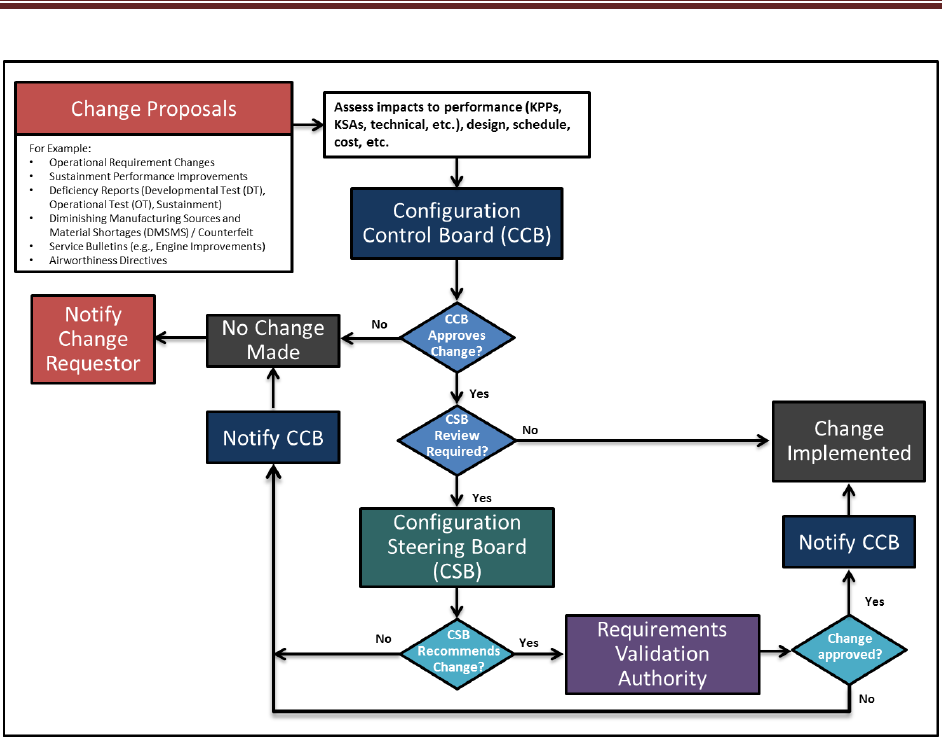
CLASSIFICATION
3 Program Technical Management
50
Source: Name Year if applicable. Classification: UNCLASSIFIED.
Figure 3.2-6 Configuration Management Process (mandatory) (sample)
o
Roles, Responsibilities, and Authorities – Summarize the roles, responsibilities, and
authorities within the Configuration Management (CM) process. If this includes one or
more configuration boards, describe the hierarchy of these boards, their frequency, who
(by position) chairs them, who participates, and who (by position) has final authority in
each. Describe how the program’s digital ecosystem tools will support the CM process if
used. Identify who has configuration control and when.
o Configuration Change Process – Outline the program processes used to change the
technical baseline/configuration and specifically address:
• How changes to a technical baseline are identified, evaluated,
approved/disapproved, recorded, incorporated, and verified
• How product information is captured, maintained, and traced back to requirements
• How requirements for in-service configuration/design changes are determined and
managed/controlled
• How internal and external interfaces are managed and controlled
• The process by which the program and external programs review configuration
changes for possible impacts on each other’s programs

CLASSIFICATION
3 Program Technical Management
51
• How the IP strategy affects and influences the planned configuration control
processes, and embed or attach that strategy to the SEP.
o Classification of Change – Define the classification of change (Class 1, Class 2, etc.)
applicable to the program and approval authority. Identify by position who in the CM
process is responsible for determining the classification of a change and who (by
position) verifies/confirms/approves it.
Expectation: Program controls the conceptual, functional, allocated, and product baselines
and should be represented in a digital model, managed within the ecosystem. The Digital
Engineering implementation facilitates the management of program baselines.
Technical Data Management
The Technical Data Management process provides a framework to acquire, manage, maintain,
use, and ensure access to the technical data and computer software required to manage and
support a system throughout the acquisition life cycle (DoDI 5000.88, Para 3.4.a.(3).(h)). (See
SE Guidebook (2022), Technical Data Management Process, for additional guidance.)
The PM and Systems Engineer should ensure that data rights are identified early and
appropriate contract provisions are put in place (IAW DFARS 252.227-7013, 252.277-7014,
252.227-7015 and 252.227-7017). The SEP should address how the digital engineering
implementation will support the following activities and products:
• Data requirements
• Use of COTS software and open source software
• Technical data and software needed, when, for what purpose(s) and by what organization(s)
to support data rights decisions
• How data will be received, verified, and accepted
• How data will be stored, maintained, and controlled
• How data will be used and exchanged
• How data will be protected
The SEP identifies the models, simulations, tools, workflows, and engineering environments the
program plans to use as part of the respective planned activity. Address what data are needed
for this activity, in what tool the data are written, and what other tools will need to consume the
data. Planning should include an access control model that supports the ability of all
participants in this activity to be able to use and share the data.
Expectation: Programs should address the technical planning required to implement the data
strategy documented in the AS. Programs should acquire the appropriate rights to the interface
technical data to allow for system evolution and interoperability in accordance with the
program's IP strategy.
System Security Engineering
Describe how the program implements comprehensive system security engineering/program
protection to include hardware and software assurance, and how it integrates with the SE
processes.

CLASSIFICATION
3 Program Technical Management
52
Expectation: To maintain technology dominance, the PM will prepare a PPP in accordance
with DoDI 5000.83, Technology and Program Protection to Maintain Technological Advantage.
The PPP will serve as a technical planning tool to guide system security engineering activities,
which include software and hardware assurance for the program.
Technical Reviews, Audits and Activities
Summarize key planned systems engineering, integration, and verification activities for all future
acquisition phases, including updated risk reduction and mitigation strategies and technical and
manufacturing maturity.
• Technical Review and Audit Planning – The LSE/CE should be responsible for the overall
conduct of technical reviews. The Configuration Manager should be responsible for the
overall conduct of configuration audits (DoDI 5000.88, Para 3.4.a.(3).(k)).
o If useful, add a diagram of the process with the objective time frames for each activity
before, during, and after the technical review and audit.
o Technical reviews and audits should be conducted when the system under review is
sufficiently mature and ready to proceed to the next phase.
o Entry and exit criteria should include maturity metrics, such as required certifications
obtained, percentages of total and critical drawings released, percentage of interfaces
defined, etc.
• Technical Activities – The LSE/CE, or Technical Lead as delegated, will be responsible for
other technical activities planned within the program’s life cycle that will be used to inform
key decisions, derive mitigations and contingencies, or provide maturity status (current or
predictive) of requirement feasibility for the system, subsystem, or individual item or
product(s).
• Software Development – The SEP should describe how software will be incorporated into
the program level Technical Review and Audit process. Specifically, for system-level
technical reviews, audits, and technical baselines, describe how SWE activities (i.e., when
Agile, DevSecOps, Continuous Integration/Continuous Delivery methods are used) will be
integrated into the program-level SE processes and acquisition documents/models.
• For each planned technical review and audit, the SEP should include a technical review and
audit table (Table 3.2-11). (See SE Guidebook (2022), Technical Reviews and Audits
Overview, for additional guidance). Include all required technical reviews as listed in the
DoDI 5000.88. If the PM is not planning on conducting a required technical review, provide
a short paragraph that identifies the review and the reasoning for waiving the review.
Table 3.2-11 Technical Review and Audit Details (mandatory) (sample)
XXX Details Area
XXX Review Details
(Fill out tailored criteria for this acquisition phase, etc.)
Chairperson
Identify the Technical Review Chair.
PMO Participants Identify Positions/functions/IPTs within the program offices which are
anticipated to participate (Engineering Leads; Risk, Logistics, and
Configuration Managers; DCMA Rep., and Contracting Officer, etc.).
Anticipated Stakeholder
Participant Organizations
Identify representatives (stakeholders) from Service SE and Test,
OUSD(R&E) external dependent programs, the User, and
participants with sufficient objectivity with respect to satisfying the

CLASSIFICATION
3 Program Technical Management
53
preestablished review criteria. For ACAT ID programs, ensure that
OUSD(R&E) receives invitations to attend sub-system level reviews
as well as the system level reviews (particularly PDR and CDR) to
allow for their independent Post-PDR and Post-CDR assessment.
Independent Review Team (IRT) (for MDAPs)
Purpose (of the review)
Describe the main purpose of the review and any specific SE goals.
Entry Criteria Identify tailored Entry Criteria established for conducting an event-
driven review. (Criteria should be objective and
measurable/observable.)
Exit Criteria Identify tailored Exit Criteria. (Criteria should be objective and
measurable/observable.)
Products/Artifacts (from the
review)
List expected products from the technical review (for example):
• Established system allocated baseline
• Updated risk assessment for Engineering, Manufacturing, and
Development
• What artifacts constitute the baseline
• Assessment of SW development progress
• Updated Cost Analysis Requirements Document (CARD) or
CARD-like document based on system allocated baseline
• Updated program schedule including system and SW critical path
drivers
• Approved Life-Cycle Sustainment Plan updating program
sustainment development efforts and schedules.
• Updated list of list of Key Risks, Issues, and Opportunities and
accepted Mitigation Plans/Strategies where appropriate.
Expectation: Program plans and conducts event-driven technical reviews and audits. Program
should use a standard process for conducting technical reviews and audits. If a technical
review and audit guide and charter are available, the SEP will reference and provide. For ACAT
IB/IC programs, the PDR and CDR planning table will include Component participants who will
conduct the independent PDR Assessment and CDR Assessment.

CLASSIFICATION
Appendix
54
For Appendices B, C, D, and E a link to the applicable documents is acceptable.
Appendix A – Acronyms
Provide a list of all acronyms used in the SEP. Example List:
FMECA
Failure Mode, Effects, and Criticality Analysis
FRACAS
Failure Reporting, Analysis, and Corrective Action System
JCIDS
Joint Capabilities Integration and Development System
MRA
Manufacturing Readiness Assessment
OUSD
Office of the Under Secretary of Defense
SEP
Systems Engineering Plan
Appendix B – Item Unique Identification Implementation Plan
Attach a copy of the plan or a link to plan document(s).
Appendix C – Agile and Development Security and Operations Software
Development Metrics
Describe how the program uses SW metrics to monitor progress to plan. Discuss how often
metrics are updated and reported, at what levels within the PM and SWE Teams, and how data-
driven decisions are supported at every level (e.g. IPT Lead, Chief SE, PM, PEO, SAE).
Include a list of the metrics and describe how they will be tailored and used as part of the SW
measurement program to assess SW development progress across the development and
sustainment life cycle. Briefly describe how the metrics and measurement data will be provided
or accessed, for example SW Dashboards/SW Metrics reports, and/or direct real-time access to
contractor metrics and data.
When implementing the Software Acquisition Pathway (i.e., DoDI 5000.87), refer to the DAU
website (https://aaf.dau.edu/aaf/software/) for the recommended set of metrics.
Agile Software Development Metrics
For programs employing Agile development and continuous integration methods, include the
following minimum set of metrics, in addition to the TPM SW metrics identified in Table 3.2-2.
Agile measures should be reported and aggregated where applicable.
• Sprint Management
1. Sprint Velocity. Report number of story points per sprint; planned and actual.
2. Average Cycle Time. Report average time between starting and completing tasks, in
time-series.
3. Burn-down (Hours or Story Points). Report hours or story points remaining, in time-
series.
4. Discuss what went well and what can be improved for the completed sprint

CLASSIFICATION
Appendix
55
• Development and Continuous Integration
1. Build Automation. Report % steps automated.
2. Average Builds per Day/Week. Report by Pass, Fail.
3. Average Duration per Build. Report Minimum, Average, Maximum in hours.
4. Unit Test Coverage. Report percent automated, percent coverage.
5. Static Code Analysis Coverage. Report percent automated, percent coverage. For
weakness/vulnerability identification, report percentage findings, burn-down and/or
Pass/Fail should be included to support program planning.
6. Functional Thread Test Coverage. Report percent automated, percent coverage.
7. System Test Coverage. Report percent automated, percent coverage.
DevSecOps or CI/CD Metrics
In addition to the Agile metrics identified above, for programs employing DevSecOps or CI/CD
methodologies to SW development, test, and deployment, include the following supplemental
minimum set of metrics,.
• Environment Management
1. Number of Active Environments; e.g., Development, System Integration Lab (SIL)
(staging), Production/Operations.
2. Environment Availability. Report uptime for active environments (not including Creating,
Recovering, and Maintenance); e.g., # hours/day, #days/week.
• Environment Automation
1. Time to (Create, Activate, Recover) Environment. Report in minutes/hours, % automated
by environment (development, SIL (staging), Production/Operations).
2. Automated Environment Controls/Features Monitored and Audited. Report % by Phase.
• DoD Enterprise’s Software Modernization Initiatives and Policy Changes
The following four metrics, often referred to as the DORA 4 (DevOps Research and
Assessment), are widely used in industry to baseline and improve pipeline delivery
performance.
1. Deployment Frequency – frequency of software deployment to field/production.
2. Lead Time - time from code commit to fielding/product deployment
3. Mean Time to Recover (MTTR) – time to recover from a failure in the field/production
4. Change Failure Rate - percentage of deployments causing a failure
Expectation: Program uses measures to report progress and keep stakeholders informed.
These measures form the basis to assess current SWE status for SW maturity, Milestone
decisions, technical reviews, and risk management boards and actions.
Appendix D – Concept of Operations Description
Programs will provide the draft or approved Concept of Operations (CONOPS) as an
attachment or provide a high-level description of the CONOPS that includes mission scenarios,

CLASSIFICATION
Appendix
56
design reference missions, and operational functions of the system and the relation to the
design approach (DoDI 5000.88, Para 3.4.a.(3).(n)).
Appendix E – Digital Engineering Implementation Plan
The program will include the Digital Engineering Implementation Plan as an appendix to the
SEP. The implementation plan will serve, at a minimum, as a summary of the program’s digital
engineering implementation strategy goals, objectives, and overarching approach for such
implementation. In addition, the SEP should include details to ensure the Digital Engineering
Implementation Plan is integrated into the overall system engineering plan (DoDI 5000.88, Para
3.4.a.(3).(m)).
The Digital Engineering Implementation Plan should identify who is responsible for the digital
engineering activities the program will conduct as part of its systems engineering activities. The
program should monitor, control, and report on the implementation plan. The implementation
plan should assign digital engineering roles and responsibility. The program’s plan should
include resources for planning for digital engineering, modeling, and simulation efforts.
This plan should capture the program’s approach to establishing, evolving, maintaining,
communicating, controlling, and using models within a continuous end-to-end digital engineering
ecosystem. The plan should describe how relevant digital model(s), simulations, and digital
artifacts will support the program efforts and how program participants, OSD, Joint Staff
stakeholders, and other interdependent programs, throughout the life of the program, will have
access to the plan. The plan should include planning for any training required for
implementation and use of modeling tools and modeling actions. The program should consider
an approach that supports incremental delivery of a continuum of models, simulations, and
artifacts needed to support program events, milestones, and decisions.
The digital engineering tool chain should maintain specifications and documentation in digital
form that were historically contained in paper documents. Information contained in
specifications and documents will be available in the digital ecosystem and can be used to
publish necessary documentation as required.
Programs should document the digital engineering implementation architecture and digital tool
chain in this appendix or in the main body of the SEP. The documentation should include a list
of the automated tools used and their purpose - including tools to perform modeling and
simulation, to design, build and test the system, to maintain an ASoT, and to ensure system
security and survivability. These attributes identify the capabilities needed to perform
engineering activities and the capabilities needed to collaborate and enable ASoT information
exchange that results in a continuous integrated end-to-end digital ecosystem.
The appendix should include plans for how the digital engineering implementation will support
the program organization. Topics include but are not limited to:
Modeling Methodologies: Describe how each of the following will be provided and used and
who is responsible for providing it.
• Definition of and or identification of methods, processes, and tools for implementing
modeling methodologies for the integrated modeling environment.

CLASSIFICATION
Appendix
57
• Definition of modeling standards, guidelines, and templates that will be needed to support
digital engineering desired capabilities.
Configuration Control Baseline: Describe plans for the development of a robust, executable
process for managing models throughout the program life cycle. The plans will also include the
roles and responsibilities required to accomplish configuration management tasks. The plans
may also include the necessary naming, marking, tagging necessary to make the models
discoverable, accessible, reusable, and trusted.
Authoritative Data: Describe plans for developing configuration-controlled repositories to
establish and maintain an authoritative source of truth for engineering data. Plan to make it
accessible to the appropriate organizations. The authoritative source of truth will be the hub for
all the models and data required for specific usages. List in the plan the models to be stored in
this repository, which may include common reference models, model libraries, competency
models, program office models, certification models, process models, knowledge models, and
other models needed to perform integrated engineering activities.
Collaboration: Describe the plan for establishing the needed infrastructure and environment
for programs and projects to conduct reviews and audits, hold technical meetings, perform
analysis, and collaboratively develop models. The collaboration environment should also be
planned to ensure internal and external stakeholders (e.g. OSD, Joint Staff, and interdependent
programs) have the necessary access and availability of technical data and acquisition artifacts
needed for both short-term decisions and long-term system life cycle management in a digital
ecosystem.
Model Use: Include the scope of the program’s complete modeling, simulation, and analysis
efforts that are essential to performing engineering and system safety activities. Identify each
model and what it will be used for to support the program. In addition, identify the model owner
that is authorized to make changes and support others in its proper use. Establish and capture
the model and data within this plan along with appropriate metadata required for model
assurance and reuse purposes.
In the main body of the SEP, include details about how digital engineering implementation will
support the integrated systems engineering and system safety activities.

CLASSIFICATION
References
58
References
Note: Provide a list of documents used in the SEP. Include complete references to correspond
with text citations. Include citations and references for illustrations reprinted from another
source. Illustrations with no source information are assumed to be original to the SEP.
Example List:
Air Force Guidance Memorandum, AFPAM 63-128, Attachment 14, AFI 63-101/20-101, para
5.1.5. September 16, 2016.
https://www.netcents.af.mil/Portals/30/documents/AFI%20%2063_101_20_101_16%20Sept
%202016.pdf?ver=2016-09-27-123456-923
Chemical, Biological, Radiological, and Nuclear (CBRN) Survivability
https://www.dodtechipedia.mil/dodwiki/display/techipedia/Chemical%2C+Biological%2C+Ra
diological%2C+and+Nuclear+Survivability.
DCMA-EA PAM 200.1. Earned Value Management System (EVMS) Program Analysis
Pamphlet (PAP). Fort Belvoir: Defense Contract Management Agency, October 2012.
http://www.dcma.mil/LinkClick.aspx?fileticket=0CBjAarXWZA%3d&portalid=31
DoD Corrosion Prevention and Control Planning Guidebook for Military Systems and
Equipment. Washington, D.C.: Office of the Under Secretary of Defense for Acquisition and
Sustainment, August 2022.
DoD Directive 5000.01, “The Defense Acquisition System,” September 9, 2020.
DoD Instruction 5000.02. Operation of the Adaptive Acquisition Framework. Under Secretary of
Defense for Acquisition and Sustainment, January 23, 2020. Available at:
https://www.esd.whs.mil/Portals/54/Documents/DD/issuances/dodi/500002p.pdf
DoD Instruction 5000.82, “Acquisition of Information Technology (IT),” April 21, 2020.
DoD Instruction 5000.83. Technology and Program Protection to Maintain Technological
Advantage, Publishing Office, July 20, 2020.
DoD Instruction 5000.85, “Major Capability Acquisition”, August 6, 2020.
DoD Instruction 5000.87, “Operation of the Software Acquisition Pathway,” October 2, 2020.
https://www.esd.whs.mil/Portals/54/Documents/DD/issuances/dodi/500087p.PDF?
DoD Instruction 5000.88, “Engineering of Defense Systems,” November 18, 2020.
DoD Instruction 8582.01, “Security of Non-DoD Information Systems Processing Unclassified
Nonpublic DoD Information,” December 9, 2019.
DoDEA Administrative Instruction 8510.01, “Risk Management Framework for DoDEA
Information Technology,” October 29, 2019.
Engineering of Defense Systems Guidebook. Washington, D.C.: Office of the Under Secretary
of Defense for Research and Engineering, February 2022.
Human Systems Integration (HSI) Guidebook. Washington, D.C.: Office of the Under Secretary
of Defense for Research and Engineering, May 2022.
Mission Assurance Guide. TOR-2007(8546)-6018 REV. B, section 10.6.3 Risk Management. El
Segundo, CA: Aerospace Corporation, June 1, 2012.
https://safe.menlosecurity.com/doc/docview/viewer/docN0F9D572D9978558133f6f1e89d56
d206a2a8e1dbbf34cbb78677356ae0291045ccb6b4945f40
Systems Engineering Guidebook. Washington, D.C.: Office of the Deputy Director for
Engineering, February 2022.
