
Copyright © 2017
PLC Electronic Solutions Ltd.
www.plcelectronicsolutions.com
Veracity Control Wheels
Wireless Operation Manual
READ ALL INSTRUCTIONS BEFORE OPERATING.
Document Number: PLC850-0010
Document Version: 032
August 2017

Copyright © 2017 PLC Electronic Solutions Ltd.
Page 2 www.plcelectronicsolutions.com
Contents
Introduction ............................................................................................................................................................................ 4
Unpacking ............................................................................................................................................................................... 5
What is in the case? ............................................................................................................................................................ 5
Mounting ............................................................................................................................................................................. 5
Connections ........................................................................................................................................................................ 6
PAN Wheel ...................................................................................................................................................................... 6
TILT/ROLL Wheel(s) ......................................................................................................................................................... 6
Power Requirements .............................................................................................................................................................. 7
Plugging In ........................................................................................................................................................................... 7
Connectors and Pinouts ...................................................................................................................................................... 8
Powering Up ........................................................................................................................................................................ 8
Veracity PPM (Wired to RC Controller) Operation ................................................................................................................. 9
Veracity Slice (Wireless) Operation ...................................................................................................................................... 10
Installing the Radio Module onto the Slice ....................................................................................................................... 10
Switching between MōVI (Standard Gimbal), Ronin and Maxima Modes ....................................................................... 12
Veracity Slide Mode Switch .............................................................................................................................................. 13
MōVI M10/M15/Standard Gimbal (Spektrum Radio) Setup ............................................................................................ 14
MōVI Pro (Spektrum Radio) Setup .................................................................................................................................... 16
DJI Ronin (Futaba Radio) Setup ......................................................................................................................................... 18
Maxima (Jeti Radio) Setup ................................................................................................................................................ 19
Basic Maxima Setup ...................................................................................................................................................... 19
Pairing the Maxima and Veracity Control Wheels ........................................................................................................ 24
Slice (Wireless) Zeroing/Drift Correction .......................................................................................................................... 25
Zeroing/Drift Correction with FoMa Control Software: ................................................................................................ 25
Zeroing/Drift Correction with MōVI App/Software (MōVI Pro App or Freefly Configurator): ..................................... 26
Gimbal Zeroing Without App/Software: ....................................................................................................................... 28
Advanced Gimbal Setup with Deadband Compensation (PLC Veracity Wheels Software) .............................................. 29
Troubleshooting .................................................................................................................................................................... 33
Pan/Tilt/Roll axes – incorrect axis control or some axes do not work ............................................................................. 33
Nothing happens – no lights, no sound, no motion.......................................................................................................... 33
Hand Wheels & Radio Controller – do not connect .......................................................................................................... 33
Axis Drifting ....................................................................................................................................................................... 33
Lights When Zeroing – do not switch from red to green .................................................................................................. 33

PLC Electronic Solutions Ltd. Copyright © 2017
www.plcelectronicsolutions.com Page 3
Tilt/Roll – does not work ................................................................................................................................................... 33
FCC Declaration ..................................................................................................................................................................... 33
Limited Warranty .................................................................................................................................................................. 34
Technical Support ................................................................................................................................................................. 34

Copyright © 2017 PLC Electronic Solutions Ltd.
Page 4 www.plcelectronicsolutions.com
Introduction
The Veracity Control Wheels System consists of:
- PAN and TILT Wheel modules, mounted together on default baseplate.
- Power cable and module interconnect cable(s).
- Selected choice of radio module (dependent on gimbal used with)
- Road case with foam insert.
- Optionally additional third axis ROLL Wheel, if ordered.
This manual describes necessary setup requirements and how to operate the Veracity Control Wheels.
The Veracity Control Wheels system is a professional digitally controlled hand wheel system for operation of RC style
camera gimbal mounts.

PLC Electronic Solutions Ltd. Copyright © 2017
www.plcelectronicsolutions.com Page 5
Unpacking
What is in the case?
The first thing to note is the Veracity Control Wheels ship in a customized Pelican Storm™ hard case, so repackaging for
field use is not required. The foam cut-outs provide spots for the PAN and TILT modules together on the default
baseplate as well as the ROLL wheel, which can be added at any time as an option to the system. There is also space for
the power cable, the interconnect cables that connect the modules and the data cable that plugs into the RC camera
mounting transmitter.
Mounting
The Veracity Control Wheels basic PAN and TILT modules come pre-mounted on a machined aluminum baseplate. It is
easy to mount this plate to any number of commercially available tripods using the centrally located 3/8-16 or ¼-20
tapped holes. The modules need to be mounted on some platform or riser so the Control Wheels are clear to rotate. If
the default mounting plate is not desirable, the individual wheel modules can be removed and mounted as needed via
the 3/8-16 hard points on the bottom of the module.

Copyright © 2017 PLC Electronic Solutions Ltd.
Page 6 www.plcelectronicsolutions.com
Connections
The Veracity Control Wheels have the following connections:
PAN Wheel
The PAN Wheel module is the ‘smart’ module. It has 4 Lemo connectors on the back of the enclosure. These are
for Power, Data, Tilt and Roll as shown. It also has 4 LEDs and a recessed switch on the same face as the
connectors.
TILT/ROLL Wheel(s)
The TILT/ROLL Wheel modules are interchangeable and have a single connector on the back of the enclosure.
This port connects to the PAN Wheel module, the TILT or ROLL connector determines which the TILT/ROLL
Wheel module will be used for.

PLC Electronic Solutions Ltd. Copyright © 2017
www.plcelectronicsolutions.com Page 7
Power Requirements
The Veracity Control Wheels are a 12V or 24V DC system. They are designed to operate with voltages from 8-30V DC
with a draw of less than 0.2 A at 12V. The Veracity Wheels system has built in reverse polarity protection and a self-
resetting internal fuse in the event of overload.
Plugging In
Before applying power, plug in all the connections except the data plug that connects into the RC transmitter. There are
3 or 4 cables that need to be plugged in to the Pan Module. The slave wheel(s) (TILT and/or ROLL), the data cable (plug
into Veracity wheels only before power up, depending on what your RC system requires) and finally the power cable.
The controls are similar to those found on most remote camera mount wheels. The sensitivity pot is an infinite ratio
control. The actual wheel to camera ratios will depend on the mount used and the scaling set up in the RC controller.
The sensitivity makes the digital pulse stream vary from 0 – 100% when the wheel is turned as fast as possible. It reduces
the hand wheel signal according to the pot position.
The direction switch is a three position switch. The center position disables the wheels output. The left and right
positions set the direction sense of the wheel.
The LED is green for one direction and red for the other and is off when the wheels are disabled.

Copyright © 2017 PLC Electronic Solutions Ltd.
Page 8 www.plcelectronicsolutions.com
Connectors and Pinouts
Data Connector
Lemo
4 pos 0S series
Pin 1) TX
Pin 2) PPM Out
Pin 3) RX
Pin 4) Gnd
Power Connector
Lemo
2 pos 0B series
Pin 1) 8-30V DC
Pin 2) Gnd
Axis 2/3 Port
Lemo
7 pos 1B series
Pin1) Switch Rev
P2) Switch Fwd
P3) Encoder A
P4) Vcc
P5) Gnd
P6) Encoder B
P7) Speed Pot
Powering Up
1) Apply power to the Veracity Control Wheels either via a battery or power supply (neither are supplied). The
Green LED over the power connector should come on immediately. If this does not, you should check your
cables and power source.
2) The Yellow LED over the data port should come on shortly after power is applied. This LED flashes indicating that
data is streaming out the data connector. The Veracity Control Wheels have no way of detecting if it is
connected to the RC controller as the communication is a one way stream.
3) The wheel direction lights are off in the center position of the direction switch, and red or green depending on
the direction selected. These will light up or not on power up accordingly.

PLC Electronic Solutions Ltd. Copyright © 2017
www.plcelectronicsolutions.com Page 9
Veracity PPM (Wired to RC Controller) Operation
The Veracity Control Wheels stream a PPM (Pulse Position Modulation) signal that is standard on many RC controllers.
They are designed to interface with the ‘trainer’ port commonly available on RC controllers.
Please see the Veracity Wired Manual for more information.

Copyright © 2017 PLC Electronic Solutions Ltd.
Page 10 www.plcelectronicsolutions.com
Veracity Slice (Wireless) Operation
The Radio Slice eliminates the need for an RC controller to wirelessly control your camera gimbal system.
Here is a step-by-step guide to get your Veracity Slice Control Wheels set-up with your receiver.
Installing the Radio Module onto the Slice
1. With the Control Wheels powered off, insert short end of the 5-pin header into the Slice receptacle.
***Note: Spare headers included with the Slice can be used in the event pins become bent or broken.
2. Using a Philips screwdriver, remove the two screws on the bracket above the Slice receptacle. Remove the
bracket.

PLC Electronic Solutions Ltd. Copyright © 2017
www.plcelectronicsolutions.com Page 11
3. Install the Futaba TM-8, Spektrum DM8 or PLC Jeti radio module into the slice, guiding the unit radio module
gently into the 5-pin header.
***Note: Squeezing the retention clips on the Radio Module may be necessary
4. Replace the bracket and screws.
5. Uninstall in reverse order (if required).

Copyright © 2017 PLC Electronic Solutions Ltd.
Page 12 www.plcelectronicsolutions.com
Switching between MōVI (Standard Gimbal), Ronin and Maxima Modes
Users can select between MōVI mode, Ronin mode and Maxima mode by following the steps below:
1. With the system powered off:
• MōVI/Ronin Mode: To select MōVI or Ronin Mode, ensure all Direction Switches for the Pan, Tilt and
Roll wheels are CENTERED, in the OFF position. With the Roll Trim Switch on the blue Slice section held
away from the wheel for MōVI Mode and towards the wheel for Ronin Mode, power on the system.
• Maxima Mode: To select Maxima Mode ensure Direction Switches for the Pan and Roll (if connected)
wheels are CENTERED, in the OFF position. Set the Tilt wheel Direction Switch in the FORWARD
position. With the Roll Trim Switch on the blue Slice section held in either direction, power on the
system.
2. The mode will be indicated at start-up to the user through the Pan wheel STATUS LED
• MōVI (Spektrum) = Green STATUS LED flashes green 4 times on start-up
• Ronin (Futaba) = Red STATUS LED flashes red 4 times on start-up
• Maxima (Jeti) = Orange STATUS LED flashes orange 4 times on start-up
The mode selection is stored in memory and will be recalled on power-up every time.
MōVI Mode
Ronin Mode

PLC Electronic Solutions Ltd. Copyright © 2017
www.plcelectronicsolutions.com Page 13
Veracity Slide Mode Switch
The MODE switch function varies depending on whether the Veracity Control Wheels are in MōVI mode, Ronin mode or
Maxima mode.
MōVI (Standard Gimbal)
With the unit in MōVI Mode, the operator has access to 3 mode-select options using the MODE select switch.
• MODE 0 - Off
• MODE 1 - Majestic Mode
• MODE 2 - Remote Mode
Ronin
With the unit in Ronin Mode, the operator has access to 3 mode-select options using the MODE select switch.
• MODE 0 - Reset
• MODE 1 - Follow Mode
• MODE 2 - 2-Person Mode
Maxima
With the unit in Maxima Mode, the operator has access to 3 mode-select options using the MODE select switch.
• MODE 0 - Off
• MODE 1 - Remote Mode (Low Speed)
• MODE 2 - Remote Mode (High Speed)

Copyright © 2017 PLC Electronic Solutions Ltd.
Page 14 www.plcelectronicsolutions.com
MōVI M10/M15/Standard Gimbal (Spektrum Radio) Setup
1. Ensure the Spektrum DM8 Radio Module is installed onto the slice.
2. Power on the MōVI System and ensure no other Spektrum Radio Controllers are powered on.
3. From the Freefly Configurator Program on your computer, place the receiver in the “Bind” state by doing the
following (See your Gimbal User Manual for model-specific instruction):
a. From your operating system, pair your MōVI with your PC via Bluetooth
b. Click CONNECTION -> Select Bluetooth…
c. Select the Receiver radio from the list of Bluetooth devices.
d. Click CONNECTION -> Connect…
e. Click CONFIGURATION… Then click Remote Controller Config.
f. Ensure “DSM2 1024” is the selected Radio Type. ***This is very important***
.
g. Click SYSTEM -> Bind Radio…
h. Turn the MōVI System off and on again to place it in a “Bind” state.

PLC Electronic Solutions Ltd. Copyright © 2017
www.plcelectronicsolutions.com Page 15
4. With the Veracity & Spektrum Slice Control Wheels powered off and the Spektrum DM8 Radio Module installed,
hold down the push-button on the DM8 Radio Module and power-on the Veracity Control Wheel System.
5. The radio light on the DM8 should initially flash red to indicate an attempt to bind, then it should arrive at a solid
light once bound.
6. See “Switching between MōVI (Standard Gimbal), Ronin and Maxima Modes” to ensure the wheels are in
MōVI Mode.
7. See the section on “Slice (Wireless) Zeroing/Drift Correction” to rectify any drifting issues.
8. To mitigate the effects of Deadband and improve wheel responsiveness. See the section “Advanced Gimbal
Setup with Deadband Compensation (PLC Veracity Wheels Software)”

Copyright © 2017 PLC Electronic Solutions Ltd.
Page 16 www.plcelectronicsolutions.com
MōVI Pro (Spektrum Radio) Setup
1. Please ensure the MōVI Pro Firmware is up to date and you have the latest version of the App. – Visit the Freefly
website for additional information.
2. Ensure the Spektrum DM8 Radio Module is installed onto the slice.
3. Connect the pre-paired Spektrum DSMX Remote Receiver Module (SPM9645) to the MōVI Pro using the MōVI
Pro COM to Spektrum Cable.
4. Power on the MōVI Pro and through the MōVI Pro app, connect using an iOS or Android device.

PLC Electronic Solutions Ltd. Copyright © 2017
www.plcelectronicsolutions.com Page 17
5. From the MōVI Pro app, in the CONFIGURATIONS > DUAL OP menu, Select DSM2 1024 and set the following
channel assignments under the Channel Mapping section:
• MODE: 6
• PAN: -2
• PAN RATE: 1
• ROLL TRIM: -4
• TILT: -3
• TILT RATE: -7
6. See “Switching between MōVI (Standard Gimbal), Ronin and Maxima Modes” to ensure the wheels are in
MōVI Mode.
7. See the section on “Slice (Wireless) Zeroing/Drift Correction” to rectify any drifting issues.
8. To mitigate the effects of Deadband and improve wheel responsiveness. See the section “Advanced Gimbal
Setup with Deadband Compensation (PLC Veracity Wheels Software)”

Copyright © 2017 PLC Electronic Solutions Ltd.
Page 18 www.plcelectronicsolutions.com
DJI Ronin (Futaba Radio) Setup
1. Ensure the Futaba TM-8 Radio Module is installed onto the slice.
2. Power on the DJI Ronin and ensure no other Futaba Radio Controllers are powered on.
3. With the Futaba TM-8 Radio Module installed, power on the Veracity & Futaba Slice Control Wheels.
4. Using a pointed (but not sharp) object, hold down the BIND button on the DJI Ronin.
5. The Bind LED on the Ronin should initially flash to indicate an attempt to bind, then should arrive at a solid light
once bound.
6. See “Switching between MōVI (Standard Gimbal), Ronin and Maxima Modes” to ensure the wheels are in
Ronin Mode.
7. See the section on “Slice (Wireless) Zeroing/Drift Correction” to rectify any drifting issues.
8. To mitigate the effects of Deadband and improve wheel responsiveness. See the section “Advanced Gimbal
Setup with Deadband Compensation (PLC Veracity Wheels Software)”

PLC Electronic Solutions Ltd. Copyright © 2017
www.plcelectronicsolutions.com Page 19
Maxima (Jeti Radio) Setup
Basic Maxima Setup
1. Launch the MAXIMA Setup Software.
2. Connect a USB cable between the Maxima gimbal and the computer. Power on the Maxima gimbal and click
Connect.

Copyright © 2017 PLC Electronic Solutions Ltd.
Page 20 www.plcelectronicsolutions.com
3. Once the Maxima gimbal is connected, configuration boxes should no longer be grayed out.
4. When the head is connected there are 5 profiles that can be modified. These correspond to the 5 profiles that
are saved in the Maxima gimbal itself that can individually be chosen via the OLED screen and menu. For the
purpose of the setup, Profile 5 will be modified.

PLC Electronic Solutions Ltd. Copyright © 2017
www.plcelectronicsolutions.com Page 21
5. You can chose to turn ON or OFF the PAN / TILT / and ROLL axis motors using the Motors On/Off Button as seen
below. It is recommended to keep the motors OFF until the profile has been fully configured and turned back
ON during the Zeroing/Drift Correction procedure. ***Note: When connected to a PC through USB, motors are
always enabled.
6. Switch to Advanced Mode by Clicking the Standard/Advanced button from the Settings > Mode Menu.

Copyright © 2017 PLC Electronic Solutions Ltd.
Page 22 www.plcelectronicsolutions.com
7. Recommended Maxima Profile Settings (FoMa Control 3.0.0.59):
• Profile > Motors: Dependent on Camera Setup (weight/size) - See Maxima User Manual
• Profile > Joystick:
o Speed: 100 (for Pan, Tilt and Roll)
o Mode: Speed (for Pan, Tilt and Roll) ***If no roll wheel, set to Angle***
o Delay: 2 (for Pan, Tilt and Roll) – Higher values increase smoothness but add input delay
o Joystick Deadband: between 2-10*
• *Set Joystick Deadband as low possible such that no drift can be seen. This value is best
set after the Zeroing/Drift Correction process.
o Ramp: 0
• Profile > Follow: Leave at default, can be changed as needed to fine-tune Follow Mode.
• Device > Joystick:
o Offset: 0 (for Pan, Tilt and Roll)
• Device > Filters: Optional for noise/vibration reduction - See Maxima User Manual

PLC Electronic Solutions Ltd. Copyright © 2017
www.plcelectronicsolutions.com Page 23
***Note: These setting values are chosen to mitigate drift, optimizing speed and responsiveness when
used with the PLC Veracity Wheels Software application. As a general rule of thumb, if you increase
axis Speed values, Joystick Deadband will have to be increased to prevent drift. In order to mitigate the
effects of Deadband, complete the Advanced Setup with Deadband Compensation procedure using the
PLC Veracity Wheels Software.
8. From the Profile > Profile Menu, click Write to Device.
9. From the Device > Device Menu, click Write to Device.
10. Ensure the Jeti Radio Module is installed onto the slice.

Copyright © 2017 PLC Electronic Solutions Ltd.
Page 24 www.plcelectronicsolutions.com
Pairing the Maxima and Veracity Control Wheels
1. See “Switching between MōVI (Standard Gimbal), Ronin and Maxima Modes” to ensure the wheels are in
Maxima Mode.
2. To bind the Maxima gimbal to the Veracity Wheels, power on the Maxima and Press the OK button to get to the
Main Menu.
3. Scroll down to ‘Remote Pairing’ and press the OK button. ***Once in this mode you have 10 seconds to
complete the next step.
4. After 5 seconds, you will hear a “beep” from the Maxima. Power-on the Veracity Wheels with the Zero Button
(located on the back of the PAN Wheel) held down and release after hearing a second beep. The Jeti Radio
Module will automatically bind to the Maxima gimbal.
5. See the section on “Slice (Wireless) Zeroing/Drift Correction” to rectify any drifting issues.

PLC Electronic Solutions Ltd. Copyright © 2017
www.plcelectronicsolutions.com Page 25
Slice (Wireless) Zeroing/Drift Correction
You may notice that when Veracity Control Wheels are connected to your gimbal system, a constant ‘drift’ or movement
in a direction occurs in any of the 3 axes. This ‘drift’ is due to the Wheels sending a signal for motion when it should not
be. If you are experiencing this, the following steps will correct it.
***Note: Zeroing will need to be performed with each gimbal that is used, as the offsets required will vary.
Zeroing/Drift Correction with FoMa Control Software:
1. Switch all axis direction switches to the center position and set the Sensitivity Dials into the center of their
range.
2. Press and hold the Zero Button located on the back of the PAN Wheel, until you notice the direction LEDs on
each axis start flashing Red and Green. The system is now in Zeroing Mode.
3. From the FoMa Control software, in the Profile > Joystick menu, set Joystick Deadband [Digits] to 0 and Write
to Device to save the setting to the Maxima.
4. Ensure the motors are turned on from the Device > Motors menu.
5. Live positional values for Pan, Tilt and Roll input can be viewed under the Device > Status menu.
1. Using the each wheel’s Sensitivity Dial, adjust for the drift such that
a. almost no drift can be visually seen from the Maxima itself and
b. The positional Status values for Pan, Tilt and Roll (optional) show minimal change.
2. Some unresolvable drift may still be visible from the previous step, but will be eliminated by increasing the
Deadband [Digital] value between 2-10 and Write the setting to the Maxima. Lower Deadband values are better
so long as no drift is observed.
3. To mitigate the effects of Deadband and improve wheel responsiveness. See the following section “Advanced
Gimbal Setup with Deadband Compensation (PLC Veracity Wheels Software)”
***Note: If the Sensitivity dial reaches the endpoint of its rotational range with its axis still drifting:
1. Press and hold the Zero Button to exit from Zeroing Mode.
2. Re-center the Sensitivity Dial.
3. Press and hold the Zero Button to get back into Zeroing Mode and continue to adjust for drift.

Copyright © 2017 PLC Electronic Solutions Ltd.
Page 26 www.plcelectronicsolutions.com
Zeroing/Drift Correction with MōVI App/Software (MōVI Pro App or Freefly Configurator):
1. Switch all axis direction switches to the center position and set the Sensitivity Dials into the center of their
range.
2. Press and hold the Zero Button located on the back of the PAN Wheel, until you notice the direction LEDs on
each axis start flashing Red and Green. The system is now in Zeroing Mode.
3. From the gimbal system software, enter the monitoring screen to view signal data. *From the MōVI Pro app,
this can be found under MONITOR > CHARTS > Radio*
• Click CHARTS, then under the Radio submenu, you can view a chart streaming the signal data. The “RC
cmd Tilt”, “RC cmd Pan” and “RC cmd Roll Trim” should be at 1500 μs. This equates to the gimbal
seeing a “zero/centered” input.
a. Using the Sensitivity Dial on each wheel, adjust the signal so that the RC cmd value for the
corresponding wheel is at 1500 μs and no drift can be seen.
• Pan Wheel = “RC cmd Pan” = 1500 μs
• Tilt Wheel = “RC cmd Tilt” = 1500 μs
• Roll Wheel = “RC cmd Roll Trim” = 1500 μs (*If connected to optional Roll Wheel)

PLC Electronic Solutions Ltd. Copyright © 2017
www.plcelectronicsolutions.com Page 27
4. Once the drift has been corrected, press and hold the Zero Button until the LEDs stop flashing and are lit solid,
then release. The LEDs will go off. The new offsets will be stored in the Veracity Control Wheels flash memory.
***Note: If the Sensitivity dial reaches the endpoint of its rotational range with its axis still drifting:
1. Press and hold the Zero Button to exit from Zeroing Mode.
2. Re-center the Sensitivity Dial.
3. Press and hold the Zero Button to get back into Zeroing Mode and continue to adjust for drift.

Copyright © 2017 PLC Electronic Solutions Ltd.
Page 28 www.plcelectronicsolutions.com
Gimbal Zeroing Without App/Software:
1. Switch all axis direction switches to the center position and set the Sensitivity Dials into the center of their
range.
2. Press and hold the Zero Button located on the back of the PAN Wheel, until you notice the direction LEDs on
each axis start flashing Red and Green. The system is now in Zeroing Mode.
3. Note the direction, rate of movement and axis of the drift on your gimbal. Using the Sensitivity Dial on each
wheel, adjust the signal until no drift can be seen on each axis.
4. Once the drift has been corrected, press and hold the Zero Button until the LEDs stop flashing and are on solid,
then release. The LEDs will go off. The new offsets will be stored in the Veracity Control Wheels flash memory.
***Note: If you do not have a Roll Wheel but do have a Blue Slice (with Roll Trim), plug the Tilt/Roll Wheel into the
Roll Wheel connector, zero out this axis, press the Zero Button as in step 4 and power off the unit. Now plug the
Tilt/Roll Wheel into the Tilt Wheel connector, power up the unit and calibrate the tilt and pan axis. If the Tilt/Roll
Wheel is unplugged while the unit is powered the settings will return to default.
***Note: If the Sensitivity dial reaches the endpoint of its rotational range with its axis still drifting:
1. Press and hold the Zero Button to exit from Zeroing Mode.
2. Re-center the Sensitivity Dial.
3. Press and hold the Zero Button to get back into Zeroing Mode and continue to adjust for drift.

PLC Electronic Solutions Ltd. Copyright © 2017
www.plcelectronicsolutions.com Page 29
Advanced Gimbal Setup with Deadband Compensation (PLC Veracity Wheels
Software)
Important: This software requires a Windows PC with a DB9 Serial port (or a USB to DB9 adapter). This also requires
Veracity Firmware Version 4.09.1 or higher. Please visit our website for software downloads and more information on
updating your firmware to the latest version.
Completing this procedure will minimize the effects of Deadband, minimizing drift, while increasing wheel motion
responsiveness. This especially useful for low-speed shots and detailed movement.
1. Ensure you have completed the basic gimbal setup procedures including zeroing from the previous sections and
ensure your wheels and Maxima are currently powered-on and communicating with Motors On.
2. Once the Gimbal and Wheels have been zeroed, connect your PC to the Veracity wheels via the DB9 Serial Data
Cable (PLC940-0029).
3. Launch the PLC Veracity Wheels Software.

Copyright © 2017 PLC Electronic Solutions Ltd.
Page 30 www.plcelectronicsolutions.com
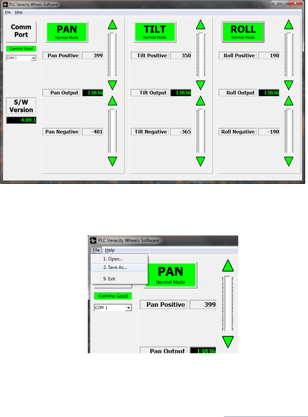
4. From the drop-down menu, select the PC’s designated COM port (COM 1 in this example). A list of assigned
COM ports can be found from the Windows Device Manager (Press the “Windows key”, type “Device Manager”
and hit Enter).
5. Once connected the Comm Port status should change to “Comms Good” in Green. The firmware version in your
Veracity Wheels will also be displayed. If unable to connect, you may have selected the incorrect port or require
a Veracity firmware update. If the wheels become disconnected at any point, the Comm Port status will change
to “Comms Lost”.

PLC Electronic Solutions Ltd. Copyright © 2017
www.plcelectronicsolutions.com Page 31
6. With your wheels and Gimbal powered and idle, turn the Sensitivity Knobs on each of your wheels fully
clockwise to 100%.
7. Starting with the Pan Wheel, increase the Pan Positive value until you notice the gimbal begin to pan in one
direction. Adjust this value to the point where only the slightest amount of movement can be noticed.
8. Once satisfied, click on the large PAN Button to save the value to Veracity memory.
9. Now raise the Pan Negative value until you notice the gimbal begin to pan in the opposite direction. Adjust this
value to the point where only the slightest amount of movement can be noticed.
10. Click on the large PAN Button to save the value to Veracity memory.
Copyright © 2017 PLC Electronic Solutions Ltd.
Page 32 www.plcelectronicsolutions.com
11. Repeat steps 7 to 10 but for the Tilt and Roll (if roll is used) Axes.
12. Once values for all axes have been set, ensure all Axes buttons are green. The wheels are now optimized for
Deadband compensation and increased wheel motion responsiveness.
13. Parameters can be saved to file and opened later from the “File” menu. This may be useful for use with different
profiles or if values are reset during a software update.
***Note: This procedure must be performed for any changes to your Gimbal Setup Profile or after re-zeroing
your wheels.

PLC Electronic Solutions Ltd. Copyright © 2017
www.plcelectronicsolutions.com Page 33
Troubleshooting
Pan/Tilt/Roll axes – incorrect axis control or some axes do not work
Check that the Veracity wheels start up in the correct mode for your gimbal (MōVI, Maxima, or Ronin). See section on
“Switching between MōVI (Standard Gimbal), Ronin and Maxima Modes”.
Nothing happens – no lights, no sound, no motion
Check wiring and ensure power is available on the Veracity Control Wheels. Make sure that your power cable is the
correct polarity for this system.
Hand Wheels & Radio Controller – do not connect
Go to the Appendices section to set up your radio controller or refer to your RC controller manual for information on
configuring the Trainer port. Check that Channels 2, 3, 4 are assigned properly
Axis Drifting
If one or more axis are drifting the system needs to be calibrated for your gimbal, please see the Zeroing section in this
manual. If drift persists, try rebalancing your gimbal and running an auto-calibration from your gimbal (i.e. for the
Maxima, calibrate the gyros and accelerometers).
Lights When Zeroing – do not switch from red to green
When zeroing the switch must be in the middle position to zero the PAN, TILT or ROLL Wheel properly.
Tilt/Roll – does not work
Make sure that all of your cables are connected to the correct ports, you may have your tilt/roll axis plugged into the
incorrect Axis Connector. Make sure that the light is red or green but not flashing.
FCC Declaration
Class B
This device complies with Part 15 of the FCC Rules. Operation is subject to the following two conditions:
(1) this device may not cause harmful interference, and (2) this device must accept any interference
received, including interference that may cause undesired operation.

Copyright © 2017 PLC Electronic Solutions Ltd.
Page 34 www.plcelectronicsolutions.com
Limited Warranty
PLC Electronic Solutions Ltd. warrants this equipment for 1 year from the date of original purchase against defects in
materials or workmanship, provided it was purchased from an authorized dealer. This warranty does not cover
equipment, which has been abused or damaged by careless handling or shipping, nor does it cover products subjected
to customer alteration, modification, negligence or misuse. This warranty does not apply to used or demonstrator
equipment.
Should any defect develop within the warranted time period, PLC Electronic Solutions Ltd. will at its sole option, repair
or replace the defective instrument without charge. To obtain warranty service, the defective instrument must be
returned within 1 year from the original purchase date to PLC Electronic Solutions Ltd., along with a brief description of
the defect claimed. PLC Electronic Solutions Ltd. will pay for ground shipping of any unit deemed to be covered under
warranty. Under no circumstances will PLC Electronic Solutions Ltd. be liable for greater than the original purchase cost
of the PLC Electronic Solutions Ltd. product.
Technical Support
Address any technical question to:
9-3871 North Fraser Way
Burnaby, BC V5J 5G6
Canada
1-877-832-3476
Hour of Operation:
Monday to Friday, 8:00 pm - 4:00 PM PST
E-mail: info@plcelectronicsolutions.com

PLC Electronic Solutions Ltd. Copyright © 2017
www.plcelectronicsolutions.com Page 35
Notes

Copyright © 2017 PLC Electronic Solutions Ltd.
Page 36 www.plcelectronicsolutions.com
Notes
