
HHPC 10061
Verify this is the correct version before use.
Information Management Platform for
Data Analytics and Aggregation (IMPALA)
System Design Document
Human Health and Performance Directorate
Human Systems Engineering and Development Division
Configuration Controlled HHPD TRB
Verify that this is the correct version before use.
August 2016
Baseline
National Aeronautics and Space Administration
Lyndon B. Johnson Space Center
Houston, Texas 77058

HHPC 10061
CONTRACTOR APPROVAL SHEET
Information Management Platform for
Data Analytics and Aggregation (IMPALA)
System Design Document
Contract Number: T73062
PREPARED BY: //original signature on file// 08/16/2016
Akinyele Akinyelu DATE
LM Senior Architect
APPROVED: //original signature on file// 08/17/2016
Alan Ruter DATE
LM Project Manager
HHPC
APPROVED: //original signature on file// 08/22/2016
Ram Pisipati DATE
Project Integrator
HHPC
APPROVED: //original signature on file// 08/23/2016
Keith Kreutzberg DATE
Wyle Technical Representative
HHPC
NATIONAL AERONAUTICS AND SPACE ADMINISTRATION
Lyndon B. Johnson Space Center
Houston, Texas

HHPC 10061
NASA APPROVAL SHEET
Information Management Platform for
Data Analytics and Aggregation (IMPALA)
System Design Document
APPROVED: //original signature on file// 08/30/2016
Andrew Carnell DATE
Enterprise Architect/SF5
NASA
APPROVED: //original signature on file// 08/30/2016
Kathy Johnson-Throop DATE
Information Systems Architecture Branch Chief/SF5
NASA
NATIONAL AERONAUTICS AND SPACE ADMINISTRATION
Lyndon B. Johnson Space Center
Houston, Texas

HHPC 10061
CHANGE HISTORY
REVISION/
CHANGE
DATE AUTHORIZATION DESCRIPTION OF CHANGE
— 8/30/2016 IMPALA TRB Baseline Release
HHPC 10061
i
Verify that this is the correct version before use.
TABLE OF CONTENTS
1.0 INTRODUCTION ...................................................................................................................................... 1-1
1.1 PURPOSE OF THE SYSTEM DESIGN DOCUMENT ............................................................................................. 1-1
2.0 GENERAL OVERVIEW AND DESIGN GUIDELINES/APPROACH ................................................................... 2-1
2.1 GENERAL OVERVIEW ................................................................................................................................... 2-1
2.2 ASSUMPTIONS/CONSTRAINTS/RISKS ............................................................................................................ 2-2
2.2.1 Assumptions ......................................................................................................................................... 2-2
2.2.2 Constraints ........................................................................................................................................... 2-3
3.0 DESIGN CONSIDERATIONS ...................................................................................................................... 3-1
3.1 GOALS ....................................................................................................................................................... 3-1
3.2 DEPENDENCIES ........................................................................................................................................... 3-1
4.0 OVERALL SYSTEM ARCHITECTURE ........................................................................................................... 4-1
4.1 LOGICAL ARCHITECTURE.............................................................................................................................. 4-2
4.1.1 Capture ................................................................................................................................................ 4-3
4.1.2 Transport.............................................................................................................................................. 4-4
4.1.3 Refine ................................................................................................................................................... 4-4
4.1.4 Store ..................................................................................................................................................... 4-5
4.1.5 Analyze ................................................................................................................................................. 4-5
4.1.6 Distribute ............................................................................................................................................. 4-6
4.1.7 Manage ................................................................................................................................................ 4-6
4.2 FUNCTIONAL ARCHITECTURE ....................................................................................................................... 4-7
4.3 INFRASTRUCTURE ARCHITECTURE .............................................................................................................. 4-10
4.4 NETWORK ARCHITECTURE ......................................................................................................................... 4-12
4.5 SECURITY ARCHITECTURE .......................................................................................................................... 4-14
5.0 DATA GOVERNANCE FRAMEWORK ......................................................................................................... 5-1
6.0 OPERATIONAL SCENARIOS...................................................................................................................... 6-1
6.1 END USER USAGE SCENARIOS ...................................................................................................................... 6-1
6.1.1 Data Ingestion...................................................................................................................................... 6-1
6.1.2 Profiling and Cataloging Data.............................................................................................................. 6-3
6.1.3 Manually Edit Data .............................................................................................................................. 6-4
6.1.4 Create, Manage and Share Data sets .................................................................................................. 6-7
6.2 ADMINISTRATOR USAGE SCENARIOS ............................................................................................................ 6-7
6.2.1 User Provisioning ................................................................................................................................. 6-7
6.2.2 System Monitoring ............................................................................................................................... 6-8
6.2.2.1 Log Aggregation ........................................................................................................................................... 6-8
6.2.2.2 Health and Availability Monitoring .............................................................................................................. 6-9
6.2.3 System Patching and Updates ........................................................................................................... 6-10
6.2.4 Backup & Recovery ............................................................................................................................ 6-10
6.2.4.1 Data Backup Schedule ................................................................................................................................ 6-10
6.2.4.2 Virtual Machine (VM) Backup .................................................................................................................... 6-12
7.0 DETAILED DESIGN ................................................................................................................................... 7-1
7.1 INFRASTRUCTURE DETAILED DESIGN ............................................................................................................ 7-1
7.1.1 Application Nodes ................................................................................................................................ 7-2
7.1.2 Enterprise Data Hub ............................................................................................................................. 7-4
7.1.2.1 Master Nodes ............................................................................................................................................... 7-5
HHPC 10061
ii
Verify that this is the correct version before use.
TABLE OF CONTENTS (Cont'd)
7.1.2.2 Data Nodes ................................................................................................................................................... 7-6
7.1.3 Storage Node ....................................................................................................................................... 7-7
7.1.4 System Software Specifications ........................................................................................................... 7-8
7.1.5 Power consumption ............................................................................................................................. 7-8
7.2 SECURITY DETAILED DESIGN ........................................................................................................................ 7-9
7.2.1 Perimeter Security .............................................................................................................................. 7-11
7.2.2 IMPALA Authentication Module ........................................................................................................ 7-11
7.2.3 IMPALA RBAC Module ........................................................................................................................ 7-14
7.2.4 IMPALA Encryption Module ............................................................................................................... 7-19
7.2.5 IMPALA Auditing ................................................................................................................................ 7-21
7.2.5.1 Navigator Audit .......................................................................................................................................... 7-21
7.2.5.2 Navigator Lineage ...................................................................................................................................... 7-22
7.2.5.3 Waterline ................................................................................................................................................... 7-22
7.2.5.4 Server Security Auditing ............................................................................................................................. 7-22
7.2.5.5 Anti-Virus Monitoring ................................................................................................................................ 7-22
8.0 INTERFACES ............................................................................................................................................ 8-1
8.1 INBOUND INTERFACES ................................................................................................................................. 8-1
8.2 OUTBOUND INTERFACES ............................................................................................................................. 8-1
APPENDIX A ACRONYMS AND ABBREVIATIONS ............................................................................................. A-1
LIST OF TABLES
TABLE 4.1-1 MAPPING OVERVIEW: USER ROLES TO IMPALA PLATFORM LAYERS ...................................................... 4-3
TABLE 4.5-1 SECURITY FUNCTION TO TOOL MAPPING ......................................................................................... 4-17
TABLE 6.1-1 SAMPLE USAGE SCENARIOS MAPPED TO IMPALA ROLES AND LAYERS ................................................... 6-1
TABLE 7.1.1-1 IMPALA VIRTUAL INFRASTRUCTURE SOFTWARE AND FUNCTIONS ....................................................... 7-2
TABLE 7.1.1-2 IMPALA APPLICATIONS AND FUNCTIONS .......................................................................................... 7-2
TABLE 7.1.1-3 IMPALA APPLICATION NODE CONFIGURATION .................................................................................. 7-4
TABLE 7.1.2.1-1 IMPALA MASTER NODE CONFIGURATION ........................................................................................ 7-5
TABLE 7.1.2.2-1 IMPALA DATA NODE CONFIGURATION ............................................................................................ 7-7
TABLE 7.1.3-1 IMPALA STORAGE NODE CONFIGURATION ...................................................................................... 7-7
TABLE 7.1.4-1 SERVER-SIDE OPERATING SYSTEMS AND COUNT ................................................................................. 7-8
TABLE 7.1.5-1 POWER CONSUMPTION ................................................................................................................... 7-8
TABLE 7.1.5-2 POWER CONSUMPTION (CONTINUED) .............................................................................................. 7-9
TABLE 7.2-1 PROTECTION POINT TO IMPALA MODULE MAPPING ......................................................................... 7-9
TABLE 7.2.2-1 IMPALA AUTHENTICATION SECURITY MODULE TERMINOLOGIES ...................................................... 7-13
TABLE 7.2.3-1 IMPALA COMPONENT ROLES AND PRIVILEGES ................................................................................ 7-14
TABLE 7.2.3-2 IMPALA SENTRY COMPONENTS AND FUNCTIONS ............................................................................ 7-17
TABLE 7.2.3-3 RECORD SERVICE COMPONENTS AND FUNCTIONS .......................................................................... 7-18
TABLE 7.2.4-1 IMPALA ENCRYPTION COMPONENTS AND FUNCTIONS ..................................................................... 7-20
HHPC 10061
iii
Verify that this is the correct version before use.
LIST OF FIGURES
FIGURE 4.1-1 IMPALA KEY ENABLERS AND PLATFORM LOGICAL ARCHITECTURE ................................................... 4-2
FIGURE 4.2-1 LAYERED FUNCTIONAL VIEW OF IMPALA PLATFORM ..................................................................... 4-7
FIGURE 4.3-1 OVERVIEW OF INFRASTRUCTURE ARCHITECTURE ......................................................................... 4-10
FIGURE 4.4-1 NETWORK ARCHITECTURE OVERVIEW ......................................................................................... 4-13
FIGURE 4.5-1 IMPALA SECURITY OVERVIEW .................................................................................................... 4-15
FIGURE 4.5-2 USER AUTHENTICATION PROCESS OVERVIEW ............................................................................... 4-16
FIGURE 6.1.1-1 DATA INGESTION FLOW ................................................................................................................ 6-2
FIGURE 6.1.2-1 DATA CATALOGING FLOW ............................................................................................................ 6-3
FIGURE 6.1.3-1 PERSISTENT MANUAL EDIT OF GENERATED DATA SET .................................................................... 6-5
FIGURE 6.1.3-2 IN-PLACE ROW/CELL MANUAL EDITS OF GENERATED DATASET ........................................................ 6-6
FIGURE 6.2.1-1 IMPALA USER PROVISIONING PROCESS ......................................................................................... 6-8
FIGURE 6.2.2.1-1 IMPALA LOG AGGREGATION PROCESS .......................................................................................... 6-9
FIGURE 6.2.4.1-1 IMPALA BACKUP SCHEDULE – SHORT TERM ................................................................................ 6-11
FIGURE 7.1-1 IMPALA PLATFORM AND HARDWARE POWER DETAILS .................................................................. 7-1
FIGURE 7.1.2-1 ENTERPRISE DATA HUB SERVICE LAYOUT ....................................................................................... 7-5
FIGURE 7.2-1 IMPALA SECURITY OVERVIEW .................................................................................................... 7-10
FIGURE 7.2.1-1 PERIMETER SECURITY ................................................................................................................. 7-11
FIGURE 7.2.2-1 IMPALA AUTHENTICATION FLOW DIAGRAM ................................................................................ 7-12
FIGURE 7.2.3-1 IMPALA AUTHORIZATION FLOW DIAGRAM ................................................................................. 7-16
FIGURE 7.2.4-1 IMPALA ENCRYPTION FLOW DIAGRAM ....................................................................................... 7-19
FIGURE 7.2.4-2 INTEGRATION BETWEEN THE IMPALA DATA RESERVOIR AND
THE IMPALA ENCRYPTION COMPONENTS .................................................................................... 7-21

HHPC 10061
1-1
Verify that this is the correct version before use.
1.0 INTRODUCTION
The System Design Document (SDD) is a compendium of three documents, providing a single source for
requirements, system design, and data design. The functional and non-functional requirements are
drawn from the Information Management Platform for Data Analytics and Aggregation (IMPALA)
System Requirements document. The three elements of requirements, user design, and data design
form the baseline from which to build a set of more technical system design specifications for the final
product, providing both high-level system design and low-level detailed design.
NOTE: For the remainder of this document, the Information Management Platform for Data
Analytics and Aggregation (IMPALA) is referred to as the IMPALA Platform.
The SDD delineates design goals and considerations, provides a high-level overview of the system
architecture, and describes the system data design, the human-machine interfaces, and operational
scenarios. The high-level system design is decomposed into low-level detailed design specifications for
each system component, including hardware, internal communications, software, system integrity
controls, and interfaces.
1.1 PURPOSE OF THE SYSTEM DESIGN DOCUMENT
The System Design document tracks the design activities that are performed to guide the integration,
installation, verification, and acceptance testing of the IMPALA Platform. The inputs to the design
document are derived from the activities recorded in Tasks 1 through 6 of the Statement of Work
(SOW), with the proposed technical solution being the completion of Phase 1-A. With the
documentation of the architecture of the IMPALA Platform and the installation steps taken, the SDD will
be a living document, capturing the details about capability enhancements and system improvements
to the IMPALA Platform to provide users in development of accurate and precise analytical models. The
IMPALA Platform infrastructure team, data architecture team, system integration team, security
management team, project manager, NASA data scientists and users are the intended audience of this
document.
The IMPALA Platform is an assembly of commercial-off-the-shelf (COTS) products installed on an
Apache-Hadoop platform. User interface details for the COTS products will be sourced from the COTS
tools vendor documentation. The SDD is a focused explanation of the inputs, design steps, and
projected outcomes of every design activity for the IMPALA Platform through installation and
validation.
HHPC 10061
2-1
Verify that this is the correct version before use.
2.0 GENERAL OVERVIEW AND DESIGN GUIDELINES/APPROACH
This section describes the principles and strategies used as guidelines in the design of and
implementation of the IMPALA Platform.
2.1 GENERAL OVERVIEW
Wyle Science, Technology, and Engineering Group (Wyle) is the prime contractor of NASA’s Human
Health and Performance Contract (HHPC), providing engineering, clinical, occupational health
surveillance, and flight hardware support to NASA’s Human Health and Performance Directorate
(HH&P). To meet its mission, HH&P collects, analyzes, and generates reports from a plethora of data in
support of crewmember occupational health surveillance and epidemiologic investigation activities,
laboratory testing, crew safety evaluations, scenario modeling, intelligence and evidence gathering,
environmental assessments, and medical countermeasures deployment.
While Wyle is currently able to meet our NASA customer’s data integration needs to meet mission
objectives with the current system and processes, NASA faces a number of process and technical
challenges.
• Inefficient, manual processes to gain access to internal and external data
• Legacy system challenges that prevent/limit automated integration of data from multiple
sources and a comprehensive view (and reuse) of laboratory, crew health records,
environmental and epidemiological data
• Lack of common processes, advanced analytics capability, and formats and controls needed to
effectively analyze, visualize, and share/reuse data across multiple systems and users
• Labor-intensive data request fulfillment processes that depend on manual data aggregation and
manual quality control reviews
• Limited or inefficient data visualization, management, governance and data sharing capabilities
(tools, skills and processes)
• Insufficient controls to store, process, and analyze longitudinal crewmember health data with
changes to metrics, data types, and units over time.
• Inability to apply descriptive, predictive, and prescriptive analytics tools across an array of
constantly changing data sets
• Inability to capture and retain meta-data on analysis and use of data, in principle, by any and all
users
A more effective method to manage astronaut health data and increase personnel productivity must be
developed. To meet the above challenges and needs, Wyle seeks to implement a data analytics
platform that will electronically integrate, manage, analyze, visualize, report on and create/share
datasets of surveillance, epidemiologic, laboratory, environmental and other data in an efficient, cost-
effective, and timely manner.
The envisioned IMPALA Platform will enable Wyle to standardize a core set of processes, metrics, and
capabilities across multiple monitoring and surveillance activities, human space flight-related research
HHPC 10061
2-2
Verify that this is the correct version before use.
programs, and data requests in a more efficient and consistent manner, as well as integrate new and
existing data types and unstructured data.
The goal of this project is to plan, design, build, test, and deploy an extensible, flexible, and modular
data integration, management, collaboration, analysis, and visualization platform in support of NASA
HH&P’s occupational health monitoring and surveillance activities, and human space flight-related
research activities.
2.2 ASSUMPTIONS/CONSTRAINTS/RISKS
2.2.1 Assumptions
The IMPALA Platform infrastructure is built on both hardware and software technologies that are
influenced by industry standards. Some of these standards are in a state of evolution. To promote the
portability of software applications and to reduce overall infrastructure costs, industry standards will be
used to implement functions where they are deemed appropriate.
The following items are design assumptions for IMPALA’s initial implementation.
1. The MEME network team will provide cabling between the IMPALA rack and the Mission
Extended Medical Enterprise (MEME) network.
2. End users laptops and /or workstations used in accessing the IMPALA platform will be provided
by NASA JSC and not as a not part of the IMPALA platform.
3. Upstream connectivity to the MEME network will provided by the MEME network team.
4. The MEME network and security team will provide security and system health monitoring tools
to ensure the health and security posture of the platform.
5. The IMPALA platform will leverage the existing MEME network virtual center metadata store,
which uses an external SQL database.
6. Infrastructure services such as Domain Name Server (DNS), Active Directory (AD) are not part of
the IMPALA platform but made available from the Information Resource Directorate (IRD)
through the Network Access Control Board (NACB).
7. The IMPALA platform will not automatically patch or update applications or operating systems.
Patching and updating schedule is dependent on the MEME environment.
8. Routable addresses used for end user communication are supplied by the MEME network team
and not a part of the IMPALA platform design.
9. The MEME network team, to cover all required IMPALA systems, will provide non-routable
addresses for internal (intra-IMPALA systems) rack communications.
10. Power consumption for each IMPALA rack is not to exceed 5000 watts.
11. The IMPALA platform websites and/or web services will be registered in the System for Tracking
and Registering Applications and Websites (STRAW) by the HH&P IT Security team.
HHPC 10061
2-3
Verify that this is the correct version before use.
2.2.2 Constraints
1. The IMPALA platform will only be accessible through NASA networks via approved, dedicated
connections or Virtual Private Network (VPN) [e.g., the MEME- Secure Socket Layer (SSL) VPN
appliance].
2. The NASA/Wyle Technical Review Board (TRB) must approve all software and hardware
technologies and products selected by the Contractor before implementation.
3. The IMPALA Platform constraints may be influenced by NASA JSC Security center policies,
procedures and protocols.
HHPC 10061
3-1
Verify that this is the correct version before use.
3.0 DESIGN CONSIDERATIONS
3.1 GOALS
The goals of the IMPALA system are to:
• Increase accessibility to accurate and actionable data without compromising security
• Increase confidence in data through defined data governance processes and controls
• Enable users to improve the quality of data analysis, reports, recommendations, and decisions
substantiated by data stored in the IMPALA Platform
• Seamlessly ingest, integrate, and manage clinical, life sciences, epidemiological, environmental,
laboratory and astronaut's longitudinal health monitoring and surveillance data
• Provide automated processes to extract, cleanse, validate, transform and curate data in
multiple formats from a variety of sources based on analyst defined rules and controls
• Extract and store metadata and establish relationship between known entities and fields in the
source data
• Provide a highly scalable and available infrastructure to store, process and analyze data as well
as continuously refresh the data from the source data
• Facilitate stakeholder collaboration and real-time data sharing internally and externally with
trusted partners, universities and other government agencies to facilitate collateral exploratory
analyses and hypothesis testing by trusted outsiders and for more extensive peer review
• Provide a secure single point of access to the data in the platform for all approved users across
multiple end user devices (mobile, desktop, laptop and tablet) with appropriate platform-
specific security protocols
• Comply with NASA's security requirements and be certified to operate within the NASA
environment and comply with federal requirements for security and handling of medical PII
• Interoperate with existing NASA and HHPD systems
• Analyze and visualize data from multiple data sources in a single unified view including data
from external investigators and programs
• Correlate, aggregate, create and share datasets from multiple data sources for analysis by
internal and external scientists as well as reuse these datasets as sources for future data
requests
• Provide advanced analytics capabilities to perform data mining, data exploration and discovery
that retains meta-data on analyses and uses of the data by all users
• Support timely processing and provisioning of new data sources for platform users
3.2 DEPENDENCIES
Implementing the IMPALA system is dependent upon the following:
• MEME Infrastructure team will provide the tools for monitoring the health of the IMPALA
platform.
• HHPIT security team will provide the tools such as the CIS benchmarking software for hardening
the IMPALA systems.
HHPC 10061
3-2
Verify that this is the correct version before use.
• HHPIT security team will provide the security tools such as log aggregation agents, and
processes for auditing the IMPALA platform.
• MEME Infrastructure team will provide Antivirus package and license instructions for agents
installed on the IMPALA servers.
• IMPALA virtual center database will be backed up by the MEME Infrastructure team post
deployment of the platform.
• The MEME Infrastructure team will execute updates and patching of the IMPALA platform’s
Operating Systems.
• A Domain Name System (DNS) will be provided by the MEME network for identifying servers
and service.
• JSC Active Directory will be provided by the MEME for user profiles and authentication, as well
as group membership.
• Access to the Launchpad application will be provided for PIV card authentication.
• MEME Network will be provide network connectivity for access to the IMPALA platform for
connectivity and access.
• MEME Infrastructure team will generate template for user requests through NASA Access
Management System (NAMS)
• MEME will provide the peripherals needed for testing the IMPALA platform within the JSC
environment (laptops, network connection to IMPALA platform)
HHPC 10061
4-1
Verify that this is the correct version before use.
4.0 OVERALL SYSTEM ARCHITECTURE
The IMPALA platform uses an open framework designed to make adding, updating or swapping
components easy. The IMPALA platform is also designed to ensure scalability (ability to grow to meet
the analytics needs of NASA), availability (ability to ensure both data and systems are available to users)
and security (ensuring that the both data and systems are protected against attacks or unauthorized
access.
The IMPALA platform provides the following additional benefits to the end-user:
• Ease of use
• Data Cataloging
• High Speed Search
• Collaboration
• Self-service Dashboards and reports
The IMPALA platform will reside within the MEME network, which in turn resides within the Johnson
Space Center (JSC) network. The sub-sections to follow provide an overview of the IMPALA platform
design from the following views:
• Logical
• Functional
• Infrastructure
• Network
• Security
These views will be described from a user’s perspective and provide functional descriptions of the
components within the platform. Section 7 of this document will expand on these descriptions at a
more technical level.

HHPC 10061
4-2
Verify that this is the correct version before use.
4.1 LOGICAL ARCHITECTURE
Figure 4.1-1 IMPALA Key Enablers and Platform Logical Architecture

HHPC 10061
4-3
Verify that this is the correct version before use.
As depicted in Figure 4.1-1, the IMPALA Platform enables the NASA community of users to operate
within seven (7) key logical layers: Capture, Transport, Refine, Store, Analyze, Distribute, and Manage
Data, using the suite of components within the platform. It also supports the governance of data and
collaboration amongst the users. This section gives a brief description of the seven (7) logical layers, the
functions performed within the layer and the user community’s interaction with each layer. Table 4.1-1
provides a brief overview of the different user role groupings, as well as how they interact with the
layers of the IMPALA platform.
TABLE 4.1-1 MAPPING OVERVIEW: USER ROLES TO IMPALA PLATFORM LAYERS
Layers IMPALA Roles Function
Capture
Data Owners
Identify data sources to be ingested into IMPALA
Transport
Developers
Connect to multiple data sources
Build ETL workflows to ingest data into IMPALA data reservoir
at scale
Apply common rule-based transformations to data on ingest
Refine
Data Scientists, Data
Owners, Data Stewards
Profile data for anomalies and correct
Catalog the data by tagging
Address exceptions/errors identified during data ingest
Store
Administrator
Ensure the creations and proper access control for data landing
zones
Ensure health of data reservoir
Ensure accurate logging and auditing
Analyze
Data Scientists, Data
Analysts
Data set creation and management
Statistical and machine-learning analysis
Generation of dashboards and reports
Exploration of data
Searching, mining and ad-hoc querying
Distribute
Data Scientists, Data
Analysts
Publish insights
Package and publish generated data sets
Manage
Administrators,
Developers, Data
Stewards
Continuous monitoring of IMPALA infrastructure health.
Ensure that data is appropriately cataloged within the data
reservoir
4.1.1 Capture
The capture layer is focused on identifying data sources that are used in servicing the functions in the
analyze layer. This layer is primarily process driven and requires domain knowledge to identify the data
sources needed. Data that will initially be captured from existing data sources within the NASA
environment, which includes the EMR (Electronic Medical Record), the LSAH (MEDB Lifetime
HHPC 10061
4-4
Verify that this is the correct version before use.
Surveillance of Astronaut Health) and MEDB Sharepoint. Data sources in the capture layer are
technically outside the IMPALA platform. IMPALA interfaces with these data sources to ingest data.
The IMPALA platform is extensible and able to capture data from other types of data sources. The
platform also supports connectivity and capture/identification of relational data sources such as
ORACLE, Microsoft SQL Server, and Microsoft Access, as well as data located in file shares, cloud based
data stores and local files of varying formats (XML, CSV, JSON, PDF, and more).
The process of identifying these data sources is a collaborative effort between the HH&P IT and the
Domain subject matter experts (SMEs). The SMEs define the data of interest and the HH&P IT teams
identify the appropriate data source within the environment containing the requested data.
During this capture layer, multiple data sources are identified for transport (import) into the IMPALA
platform.
4.1.2 Transport
The transport layer of the IMPALA platform focuses on the movement of data from the production data
sources, present and future, to the IMPALA platform data store. Where the Capture layer focuses on
the identification of the data, the Transport layer contains the pipeline for bringing the data into the
IMPALA platform.
The IMPALA platform’s transport layer is not just limited to RDBMS tools previously listed (ORACLE,
Access, and MS SQL), it enables connection to any relational data source that supports ODBC or JDBC
connectors, connection to file shares and connection to data residing in the cloud.
The HHP&IT team will leverage the functions within this layer to build, test and deploy data capture
jobs. These data capture jobs will be scheduled to connect and load data from the data sources (EMR,
LSAH, etc.). As the list of production data sources grows beyond the initial data sources, this team will
support the design and development of the required data capture jobs. This team also manages the
interface to the production data source. The interfaces for relational data stores include ODBC and
JDBC as well as the credentials to connect to these production data stores. The IMPALA platform uses
built-in functions, such as secure copy or secure file transfer protocols, to import non-relational data
sources such as file. The data capture jobs are orchestrated using the Pentaho engine. Within this
engine, business rules are defined to apply static transformations to the data as it is transported into
the data reservoir.
4.1.3 Refine
In the IMPALA refine layer, data that is ingested through the transport layer are refined (selected,
standardized, tagged, categorized, summarized) and enriched either manually or automated. Users are
able to review ingested data and apply transformations or error cleaning logic to it. SMEs are also able
to use their knowledge to enrich the data with tags, labels and comments, as well as creating newly
derived fields. The data in this layer is transient, which mean it is not in its final state. It is also
important to note that all transformations or profiling functions applied to the data in this layer are
performed against an internal IMPALA copy of the original data (from the Transport layer), not the data
source.
In this layer the users, Developers, Data Owners, Data Stewards, Data Scientists and Data Analysts,
crowd-source (i.e collaborate) on their knowledge of the domain to create profiling jobs that enable the
HHPC 10061
4-5
Verify that this is the correct version before use.
cataloging of data going into the IMPALA store. These jobs can then be scheduled or called on demand
by components of the Transport layer.
The greatest benefit of the work done in this layer is that it allows for the improved efficacy of searches
against and analysis of data performed by users such as data scientists, and data analysts. The SME
community tags each data table and field that passes through the refine layer with common terms used
by end users as defined/refined.
4.1.4 Store
The IMPALA store layer provides the landing zone for captured, transported and refined data. This
landing zone is the distributed IMPALA data reservoir. Three (3) key principals govern the design of this
layer:
• Scalability
The IMPALA store layer is built using the Apache Hadoop platform. Apache Hadoop is an open
source software platform for distributed storage and processing of very large data sets on
server clusters built from commodity hardware. Because it is built on a cluster of servers,
scaling to match growth in data is as simple as adding more server hard drives or adding
another server. As the data analysis needs of NASA grow, the data size will grow. The IMPALA
platform store layer ensures that when this growth occurs the system can accommodate it.
• Redundancy
The distributed storage design of IMPALA’s Apache Hadoop data store layer ensures that every
block of data is replicated 3 times across the cluster of servers. This means that even with the
loss of a server or a hard drive, the system continues to function as normal. Built in
management modules, described in section 7, ensure that when a hardware failure occurs, an
administrator is notified. Once the server or hard drive is repaired/replaced, data is copied back
to the server/drive as it resumes as part of the cluster. In addition, this redundancy allows data
processing on a given segment of the data to be performed on any of its available copies,
reducing data processing bottlenecks and improving performance on large datasets.
• Performance
The Apache Hadoop platform supports distributed processing and the IMPALA platform design
leverages this feature by ensuring that all end user jobs/functions, such as searching, enriching,
cataloging and transforming data, are performed by all the nodes/servers in parallel in the
cluster.
With these three (3) key principals, the IMPALA platform is ensured a quick response time as well as the
confidence of data safety.
Another key function of the store layer is its ability to store data of all types. Relational databases or
file-based data such as pdfs, CSVs, DOCs, XMLs, JPGs, PNGs and more can be stored and coexist within
the IMPALA store layer. They can also be blended together.
With this layer, the users of the IMPALA platform gain access to one aggregated data source with a
variety of data types and they are able to process and use these datasets for analytics and search.
4.1.5 Analyze
The analyze layer leverages the processing power of the store layer and provides components that
enable searching and mining of data, ad-hoc querying at scale, collaborative data request fulfillment,
HHPC 10061
4-6
Verify that this is the correct version before use.
reports generation and data exploration. The data analysis and visualization tools provided with the
IMPALA platform work with the Apache Hadoop platform to handle the distributed processing
intrinsically, providing the end users with familiar functions for joining, searching, querying, and
analyzing their datasets. The user interfaces in this layer are all web-based and many provide drag and
drop capabilities and immediate feedback on a sample of the data.
NASA data scientists and analysts use the components of this layer to consume data, deliver insights,
manage relationships between different data sources, and create and edit data sets for fulfilling data
requests.
The users access this layer through a web-based portal after authenticating against the JSC active
directory domain. The IMPALA platform uses role based access control to ensure that a user is only
allowed to access or analyze the data for which they have been granted permission.
4.1.6 Distribute
Data sets created in the analyze layer may distributed or published to other users using the components
within this layer. Internal JSC users can authenticate into the IMPALA platform and view or download
generated data sets, analytic results, or visualizations.
4.1.7 Manage
In this layer, the Data Stewards and Developers develop scripts for data loading and transformation,
cataloging of data, and tagging data based on domain knowledge. These scripts are tested and then
packaged for use in the capture, transport and refine layers. The packaged scripts are accessible as web
services or through command line interfaces.
Administrators use the components of this layer to manage access and privacy of data.

HHPC 10061
4-7
Verify that this is the correct version before use.
4.2 FUNCTIONAL ARCHITECTURE
Figure 4.2-1 Layered Functional View of IMPALA platform
HHPC 10061
4-8
Verify that this is the correct version before use.
This section describes the functional purpose of each layer mentioned in the Logical Architecture
(section 4.1). It also briefly describes how the users will gain access to and interact with the platform.
The IMPALA platform will leverage the existing Johnson Space Center (JSC) NASA Access Management
System (NAMS) and process to provision users (i.e., Users will request access to IMPALA through
NAMS). An IMPALA review board reviews user access requests for approval. The IMPALA administrator
creates the user profiles and provisions the appropriate role within the IMPALA system after the NAMS
request is approved.
Based on the current MEME infrastructure, users with appropriate credentials interact with the IMPALA
platform by connecting to the JSC network from an onsite workstation or through the JSC VPN and
authenticating into the IMPALA platform.
The IMPALA portal is the web-based graphical user interface (GUI) used for accessing all the
components described in the Logical Architecture view. Access to this interface is through a web
browser on the user’s desktop workstation.
Authenticated and approved users are able to create information dashboards and visualizations,
connect to multiple data sources, define and generate a data catalog, search for data and wrangle (or
clean) data pre or post search. Each component behind the IMPALA portal is web-based and provides
drag and drop or point and click capabilities for ease of use.
The transport functional layer enables the hydration of data into the data reservoir from initial data
sources identified such as the EMR (Electronic Medical Record) or the LSAH (Lifetime Surveillance of
Astronaut Health), which reside on two (2) different relational databases (RDBMS) – Oracle and
Microsoft SQL Server (MS SQL) in the capture process. Data is processed, cleaned, and profiled during
import for the purpose of search, analytics or reporting.
Developers create Extract, Transform and Load (ETL) jobs in the transport layer using Pentaho Data
Integration tools to move/copy data. These jobs, once validated, are scheduled to ensure the data
reservoir contains fresh data. The transport layer also functions as an orchestration engine by allowing
external processes such as transformation scripts built in the refine layer, using Trifacta, to be called
outside of the standard copy of data.
The refine functional layer provides components such as Trifacta and Pentaho to create and apply rule-
based data transformations before load. Transformations created and packaged in Trifacta for
repeatable cleansing of data are referred to as static transformations. These static transformations are
provided as steps in the transport layer mentioned above.
The analyze functional layer described in section 4.1.5 consists of the components that:
• MASH reports, Dashboard, Data Catalog, Search and Data Wrangling
• enable the creation of repeatable workflows that pull data from the data reservoir,
• establish collaboration workspaces for different risk specializations,
• connect to and pull data from other data sources to enrich searches,
HHPC 10061
4-9
Verify that this is the correct version before use.
• create dashboards for reporting and informing flight surgeons and finally for creating datasets
that fulfill request for data.
The functionality within the analyze functional layer allows for the creation of MASH reports,
Dashboard, Data Cataloging, Searching and Data Wrangling as depicted in figure 4.2-1
Behind these components is the Distributed Data Reservoir (in the store layer). This component
supports the authentication and authorization within the IMPALA platform data reservoir. Each of the
services in the other layers must authenticate against the data reservoir in order to perform any
functions with the data reservoir. This authentication is controlled using Kerberos. Authorization at the
data level is accomplished via role-based access control (RBAC) using Sentry software. This layer also
enables the encryption of data at rest for privacy. Details on the authentication and encryption are
discussed section 7 of this of this document.
The IMPALA NAS (Network Attached Storage) will be used to backup the data reservoir. This process is
described in section 6.2.4.
The IMPALA platform leverages existing infrastructure management functionality within the MEME
network by providing system SNMP (Simple Network Management Protocol) traps to existing health
management tools such as SolarWinds. The MEME environment currently uses an agent-based log
aggregation tool for security auditing. To ensure compliance, these agents are installed on the MEME
servers for security auditing purposes. The MEME environment currently uses an agent-based tool, Dell
KACE, for inventory and system management. The servers within the IMPALA platform leverage the
Computer Information Security benchmark to ensure appropriate hardening of the servers.
The IMPALA platform provides an issue-tracking interface, using JIRA, that enables HHPIT and IMPALA
administrators to post issues within the platform. These issues are tracked through to resolution using
the IMPALA issue-tracking component (JIRA). JIRA also enables the tracking of updates to the IMPALA
platform by entering and tracking update requests for the new releases of functionality.
These layers work together to allow users of the IMPALA platform to work collaboratively to meet the
goals defined in section 3.1.

HHPC 10061
4-10
Verify that this is the correct version before use.
4.3 INFRASTRUCTURE ARCHITECTURE
Figure 4.3-1 Overview of Infrastructure Architecture
HHPC 10061
4-11
Verify that this is the correct version before use.
The IMPALA Platform is a self-contained rack located in the building 46 Data Center in room 300. It is
interconnected electronically with the MEME environment behind the MEME firewall. The sub-
components of the IMPALA platform are deployed as a combination of virtual machines and physical
servers. The user facing components are deployed as virtual machines across three physical hosts,
called application nodes. The IMPALA distributed data reservoir is deployed across six (6) physical
servers (2 Master Nodes and 4 Data Nodes). Communication between the application nodes and the
data nodes within the rack is through services on the Master nodes over a 10Gbe network.
The IMPALA rack contains four switches, two (2) 10Gbe switches in an HA configuration for intra-rack
communication and two (2) 1Gbe switches in an High Availability (HA) configuration for
user/management communication. The user/management switch connects to the MEME firewall for
user and management access. The IMPALA rack also contains an iSCSI Storage device used as a central
store for VMs and for backup of data within the reservoir. The backup strategy is outlined in the
Operational Scenario section.
Data from data sources such as the Electronic Medical Record (EMR), the Lifetime Surveillance of
Astronaut Health (LSAH) and Medical Evaluation Document part B (MEDB), as well as future data
sources, will be ingested into the IMPALA data nodes. Layout and landing zone information as well as
the governance processes for data loads are in the Data Governance Framework document.
As stated in section 4.2, the IMPALA Platform leverages the following existing processes and tools
within the MEME environment for health management and security posture:
• Configured SNMP traps for monitoring IMPALA Platform server components such as CPU, disk,
memory etc., as well as availability or uptime of the servers forwarded to the infrastructure
management tool provided by the MEME infrastructure team.
• Anti-virus agents, as provided by the MEME infrastructure team, are deployed on IMPALA
servers
• Server hardening leveraging the Center for Information Security (CIS) benchmarking
requirements as provided by the NASA IT security team
• Deployment of log aggregation agents as provided by the HHPIT security team for auditing
Patches to the operating system and upgrades of the individual components of the IMPALA platform
will adhere to the policies set forth by the NASA IT security team. Section 6.2.3 details the process for
patching the IMPALA platform.
The IMPALA Platform physical architecture supports high performance through the following means:
• Clustering
The data nodes are clustered enabling sharing of the workload across commodity hardware.
The Application server hosts are also clustered to ensure that the loss of one application server
does not lead to a drop in unavailability of any of the applications
• RAID Configuration
The OS hard disks for the servers within the IMPALA Platforms are in RAID-1 configuration to
ensure continued operations in the event of a hard disk failure. The storage device is
configured for RAID-6
HHPC 10061
4-12
Verify that this is the correct version before use.
• Distributed Storage
Each block of data is triple replicated across multiple disks and servers to ensure that the loss of
one drive or server does not lead to data loss
• Distributed Processors
The IMPALA Platform leverages the processors/cores across all the servers within the cluster to
ensure requests such as searching, data mining or analytics are processed fast and in a parallel
fashion
• Network Throughput
A 10Gbe intra-rack backbone ensures high speed data transfer between the master nodes, data
nodes and application nodes.
The local iSCSI storage device within the IMPALA rack serves the following purposes:
• VMDK (Virtual Machine Disk) Storage
Each application host (also known as ESXi servers) will host the virtual machines on which each
component (or application) runs. Each virtual machine (VM) will have its disk located on the
iSCSI storage devices. This design enables high availability within IMPALA’s virtual
infrastructure.
• Backup
Section 6.2.4 describes the backup process, schedule and methodology within the IMPALA
platform. The following general items will be backed up to the storage device by default:
o Application configuration files
o Application metadata information such as project files or metadata database generated
as a result of usages
4.4 NETWORK ARCHITECTURE
The IMPALA platform operates on four main networks:
• User Network
A 1Gbe network dedicated to end user communications. Two (2) IMPALA Top-of-Rack (TOR)
switch configured with HA support this network.
• Internal Cluster Network
A 10Gbe network dedicated to communications between the applications and services within
the IMPALA platform. Two 48 port 10Gbe switches support this communication. These
switches are in a High Availability (HA) configuration
1. Internal Virtual Machine (VM) Network
A 10Gbe network dedicated to communications between the virtual machines and storage unit
within the IMPALA platform.
• Management Network
A 1Gbe network dedicated to management of platform devices and monitoring the health of
the IMPALA platform. A 1Gbe network dedicated to out-of-band (OOB) management of the
servers within the IMPALA platform.
HHPC 10061
4-13
Verify that this is the correct version before use.
The connections to this network and how the IMPALA platform is connected to the MEME network is
depicted in Figure 4.4-1.
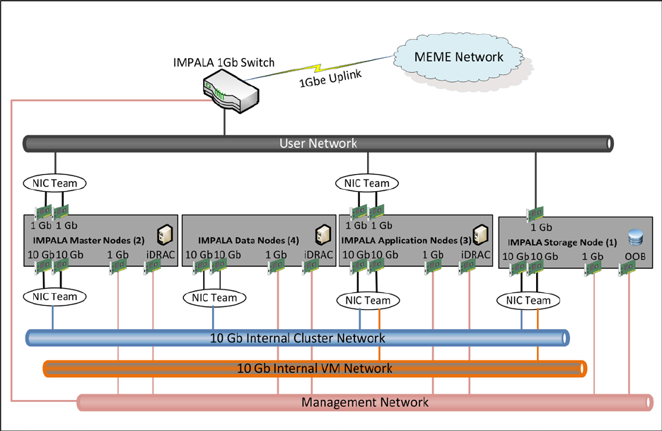
Figure 4.4-1 Network Architecture Overview
Users (Data Analysts, Data Scientist, Researchers, etc.,) interact with the IMPALA platform by
connecting to the JSC network from an onsite workstation or through the JSC VPN. Each server within
the rack is fitted with multiple Network Interface Cards (NICs), as depicted in figure 4.4-1.
The two-10Gbe NICs are configured in a NIC Team using NICS Teaming – a process of combining NICs
together for performance. These two NICs support communications on the 10Gbe Internal Cluster
Network. The Internal Cluster Network is used for communication between the applications located on
the virtual machines (VM) and the data reservoir nodes (master and data nodes). It is also used for
communication between the different components of the IMPALA data reservoir, for example,
communication between the resource manager and the data nodes.
The storage device and the application hosts (VM hosts) are also configured a 10Gbe NIC each. These
enable communication over the internal VM Network.
For communication on the User Network, each server is configured with two-1Gbe NICs also configured
in a NIC team for performance and high availability.
For communication over the Management Network, each server is configured with two-1Gbe NIC. The
first is for monitoring the IMPALA platform via management tools, as well as for patching and other
HHPC 10061
4-14
Verify that this is the correct version before use.
administrative functions that affect the OS of the servers. The second NIC is for Out-Of-Band (OOB)
communication using the iDRAC (integrated Dell Remote Access Controller). The iDRAC provides
functionality that helps in deploying, updating, monitoring and maintaining the servers with or without
a system management software agent.
4.5 SECURITY ARCHITECTURE
Security within the IMPALA platform is designed to protect the data via five (5) discrete layers:
Perimeter Security, Authentication, Authorization, Encryption and Policy.

HHPC 10061
4-15
Verify that this is the correct version before use.
Figure 4.5-1 IMPALA Security Overview

HHPC 10061
4-16
Verify that this is the correct version before use.
Perimeter security refers to the network controls that protect network access to the IMPALA platform.
The IMPALA platform is within the MEME environment, which is guarded by the MEME Firewall. For
any user to gain access to the MEME environment, they must first establish a secure Virtual Private
Network (VPN) connection.
Both users that access the IMPALA platform and services components that operate within the IMPALA
platform must authenticate to gain access to or perform any operation against the data. Users request
access to the IMPALA platform through the NAMS system. The MEME administrator based on defined
policies established in the data governance guide fulfills these requests. Users authenticate through the
NASA LaunchPad system (see Figure 4.5-2 below).
Figure 4.5-2 User Authentication process overview
Service accounts are created within the IMPALA platform for each component to communicate with the
data reservoir. These service accounts are created in Kerberos Key Distribution Center (KDC) so each
service has its own unique credentials (as keytabs) to access the data in the data reservoir and to
execute tasks against that data. This process is described in detail in section 7.
For authorization, the IMPALA system leverages a role-based access control system at the data and
component layers of the platform. It also leverages groups defined in active directory via a one way
trust between the NDC active directory and the Kerberos KDC. Sentry, described in more detail in
section 7, is used to assign privileges based on roles to each data entity within the IMPALA platform.
All data in the data reservoir is encrypted using AES-256 encryption. This ensures that malicious access
to the data does not lead to release of PII information.
Per the JSC/HHPIT security guidelines, the server OS’s are hardened using the Center for Internet
Security (CIS) guidelines to ensure a proper lockdown of the system. Antivirus and monitoring agents
are installed on all servers within the IMPALA platform. Logs for systems and application are configured
to be captured using a log aggregation tool specified by the HHPIT security team.
The table below shows a breakdown of each security function and which tool or component supports it.

HHPC 10061
4-17
Verify that this is the correct version before use.
TABLE 4.5-1 SECURITY FUNCTION TO TOOL MAPPING
Security Function
Provided by
Native/Leveraged
Perimeter Security
MEME Firewall/VPN
Leveraged
Access Control
Sentry
Native
Access Requests
NAMS
Leveraged
System Monitoring
SolarWinds
Leveraged
Security Audit Logging
Splunk
Leveraged
Application/System Audit Logging
Splunk
Leveraged
OS Hardening
CIS Benchmark
Native & Leveraged
Encryption of data at rest
Navigator Encrypt /AES-256
Native
Encryption of data in motion
TLS/SSL
Leveraged
Compliance Audit Support
Navigator Audit/Navigator
Lineage
Native
Key Management
KMS/KTS
Native
Malware & Harmful Code
Protection
TrendMicro
Leveraged
User Identity
NDC AD
Leveraged
Application Access
Kerberos
Native
User Access
Launchpad
Leveraged
Inventory/System Management
Dell KACE
Leveraged
Vulnerability Scanning
MVM
Leveraged
Software Vulnerability & Memory
Protection
EMET
Leveraged
HHPC 10061
5-1
Verify that this is the correct version before use.
5.0 DATA GOVERNANCE FRAMEWORK
A Data Governance Framework will be built for the NASA HHPC program to ensure clear communication
within the IMPALA team and across all organizations that it touches and to maintain scope and focus,
establish accountabilities, and define measurable successes. The details of the Data Governance
Framework are presented in the Data Governance Framework document.

HHPC 10061
6-1
Verify that this is the correct version before use.
6.0 OPERATIONAL SCENARIOS
The IMPALA Platform provides a single source of data for NASA data analysts, data scientists, and other
users to locate data, perform analysis, and share their investigations. The scope of functionality
provided by the tools in the IMPALA platform allows for a large number of operational scenarios. This
document will cover some of those operational scenarios most likely at the initial onset of use.
Initially, the IMPALA data reservoir is hydrated by scheduled Pentaho jobs that run either on demand or
on a scheduled basis (recurring daily or weekly) to refresh the data. On unsuccessful loads, there will be
exceptions and error logs generated. After data ingest, ETL engineers will use Trifacta to confirm data
or cleanse and transform it. Exception handling will also be handled at this stage and logged into the
system. After the data is imported and cleansed, it is ready for use by the Data Scientists and other end
users. Section 6.2, describes expected Operational Scenarios using the data imported into the IMPALA
platform.
6.1 END USER USAGE SCENARIOS
This section describes initial usage scenarios that portray end user experiences with the IMPALA
platform. These usage scenarios are grouped as End User and IT User scenarios. Table 6.1-1 is a
summary of some of the usage scenarios that are enabled by the IMPALA platform, which layer of the
platform they apply to, and which general IMPALA roles operate within those layers.
TABLE 6.1-1 SAMPLE USAGE SCENARIOS MAPPED TO IMPALA ROLES AND LAYERS
User Experience of Applies to Group Applicable IMPALA layer
Perform Data Ingestion at scale
Developer
IT User
Transport and Store
Profiling, Cataloging and managing data
Data Owner,
Data Steward
End User
Refine
Manually edit data
Data Steward,
Data Owner
End User
Analyze
Create, manage & share data sets
Data Scientist,
Data Owner,
Data Scientist
End User
Analyze and Distribute
6.1.1 Data Ingestion
The IMPALA platform leverages Pentaho Data Integrator (PDI) for ingesting data into the IMPALA data
reservoir. Pentaho Data Integrator enables developers on the HH&P IT team to create custom
workflow based jobs to pull data from the source, transform and push data into the data reservoir.
These jobs are executed on demand, or are scheduled, to hydrate the data reservoir from data sources
such as the EMR, LSAH, MEDB, and file shares hosting generated reports. The data ingest process
includes identifying data sources to ingest, identifying static transformations that need to be applied to
the data upon ingest, tracking of requests to create repeatable data ingest pipelines, creating and
executing repeatable pipelines.

HHPC 10061
6-2
Verify that this is the correct version before use.
Figure 6.1.1-1 Data Ingestion Flow
The Data Governance board identifies data sources that should be ingested into the IMPALA data
reservoir. Data scientists, Data Owner and Data Stewards define:
• Filters to ensure that data pulled into the data reservoir are relevant.
• Static transformations or business rules, like unit changes or dealing with nulls, that need to be
applied to the data upon ingest.
• Refresh intervals and other ingest parameters for the HH&P IT team to create data ingest
pipelines
The identified transformations, identified data sources, and ingest parameters are transformed into
requirements that are tracked within the JIRA component. The HH&P IT team reviews requirements
within JIRA and create:
• Sqoop jobs for reading data from a relational database and writing the data into IMPALA.
• Modular scripts used to transform the data using Trifacta and custom scripts.
• Workflows which orchestrate the connection to the data sources, the querying and filtering of
the data, and the transformation of the data as the data is pushed into the data reservoir.
In addition to creating workflows that are based on business rules (static transformations),
transformations created post initial data load using Trifacta can also the packaged and applied to future
ingests. The analysts reviews the data in the data reservoir and identifies necessary transformations
that need to be persisted. These transformations are then created using Trifacta and the ensuing script
is added to the data ingest workflow pipeline for future/subsequent data ingests.

HHPC 10061
6-3
Verify that this is the correct version before use.
6.1.2 Profiling and Cataloging Data
As part of a Data Governance framework, profiling and cataloging are organization techniques that
ensure data can be located and tracked within the data reservoir. One of the benefits of a data
reservoir include providing a single source for data of all types and origins. However, due to the size
and scope of the data reservoir capabilities, if organization techniques are not employed as the
reservoir fills, locating the desired information for analysis or visualizations can become increasingly
difficult. The Data Governance framework provides these processes to keep the data organized.
Figure 6.1.2-1 Data Cataloging Flow
The initial step for organization is determined by the folder structure used for storing data. The
incoming data is held in a landing zone within the IMPALA data reservoir while it is being profiled and
cataloged, then it is moved to a pre-established destination. Datasets and extracts created from the
original files can be tracked through the IMPALA platform using lineage and pedigree tools.
Profiling establishes metadata for incoming data on both the file and data element levels. The IMPALA
platform provides tools that perform automated profiling and tagging when the data is in the landing
zone within the IMPALA data reservoir. In addition to the tags provided by the tools, the user can
define business rules to customize tags based on the content of the incoming data. Once cataloging
and tagging jobs have been defined, a Pentaho Data Integrator workflow is defined and developed by a
developer to automate the process of cataloging and profiling when new data is placed into the landing
zone.
Cataloging the profiled data allows users to search the metadata and apply custom tags to quickly
locate files with specific content.
The Data Governance board provides the processes that will be followed for both automated and
customized profiling, cataloging, and file hierarchy. Collaboratively, Data scientists, Owners, Stewards
and Analysts define:
HHPC 10061
6-4
Verify that this is the correct version before use.
• Filters to ensure that data pulled into the data reservoir is relevant.
• Domains and tags for that data
• Filters and tags to define subject-area datasets
• Business rules for custom tagging
• Metadata searches
6.1.3 Manually Edit Data
There are many operational reasons for approved users to edit data in the data reservoir. The tools and
methods used to edit data depend on the length of time that the edit should persist, if at all they should
persist. There are generally three types of edits to data within the IMPALA platform, Persistent/Static
Transformation edits, Non-persistent/Analytic edits and In-place edits.
Persistent/Static transformation edits are applied to data prior to its landing in the data reservoir as
well as errors identified that need to be addressed for every data ingest after the initial load. The edits
that occur as data is being ingested the first time are applied using business rules built into Pentaho
workflows. The process for these edits is described in the steps below:
1. Subject Matter Expert/Analysts identifies a change that needs to be made to data before
ingestion based on historical knowledge or experience
2. A request is posted to the Developer to add business rules that edit the data in transit into the
data reservoir
3. Created business rules are inserted as steps in the data ingest workflow ensuring that the edits
are consistent and made on every data ingest
In other scenarios of persistent/static transformation edits, a subject matter expert or analyst identifies
error in the data while working with the data in the reservoir. In this scenario, the analysts uses Trifacta
to make edits to the data this process in-turn generates a scripts that can be called by the data ingest
orchestration workflow ensuring the transformation or edit is applied on subsequent ingests. This
process is depicted in Figure 6.1.3-1 below.

HHPC 10061
6-5
Verify that this is the correct version before use.
Figure 6.1.3-1 Persistent Manual Edit of Generated Data Set
Data that is generated and stored within the IMPALA data reservoir such as results of analysis or search
requests, are pulled into the wrangling tool, Trifacta. The analyst, who understands the data and the
edits that need to be made applies that transformation, executes the script, and validates the resulting
dataset. Execution of the script creates a new data set in the Data Reservoir with all the metadata
associated with the edit/transformation. A request is then sent to the ETL developer to add this script
to the data ingest process for persistent edits of data with the same structure.
Persistent edits or static transformations may include the following:
• Decomposing a compound field into multiple fields
• Unit conversions to standardize the measurement system for data of the same type (such as
dates, height, weight)
• Removing incorrect values
• Adding additional information
• Adding lookup or descriptive information
Tools used for persistent edits:
• Trifacta scripts integrated into the Pentaho workflow
Non-persisted edits generally describe edits that are made during the course of analyzing or dealing
with the data in the data reservoir. They are performed during analysis and modeling for a particular
purpose. These edits may be documented and shared with other users, but the edits only apply to the
data as it is being used in the analysis. In this type of edit, the data is not persisted and it is only used
for the duration of the analysis.
Types of edits performed during analysis may include:

HHPC 10061
6-6
Verify that this is the correct version before use.
• Removing null values
• Filtering outliers
• Deriving or calculating new fields
Tools used for edits during analysis:
• Trifacta scripts
• Alpine cleansing, filtering, or SQL functions
Regardless of which of the methods described above is used, the source data within the IMPALA
platform is never altered during editing. A copy of both the original data and the edited data are saved,
which allows for tracking and auditing of all data changes.
One last type of edit is in-place or row/cell level edits. These edits do not need to be persisted and do
not apply to the data-at-large. In this scenario, the analyst may recognize something as simple as a
misspelled word or unit on a particular row and cell within the generated dataset. In this scenario, an
out flow edit is required. First, the user must download the data set in a tabular form to their desktop.
Then using a tool such as excel, modify the row/cell with the errant data value. Once the error is
corrected, the data can then be uploaded back into the data reservoir in a location defined by the
governance process, if there is a requirement to track such change. Metadata that needs to apply to
this process is also defined in the data governance document. This metadata is used for auditing.
Figure 6.1.3-2 below is a depiction of this process.
Figure 6.1.3-2 In-Place Row/Cell Manual Edits of Generated Dataset
HHPC 10061
6-7
Verify that this is the correct version before use.
6.1.4 Create, Manage and Share Data sets
The main operational purpose of the IMPALA platform is to provide an environment that allows users to
access data from multiple data sources for data querying, creating data sets, assembling reports to
support requirements, performing analyses, and constructing dashboards and visualizations.
A user can create a new dataset by extracting, querying, editing, filtering, merging or joining existing
datasets within the IMPALA data reservoir. The resulting dataset will be stored in the IMPALA data
reservoir, where additional tags and metadata can be added. The IMPALA platform traces the lineage
of data elements and datasets, allowing the originating source(s) of the dataset to be traced using
Waterline or Cloudera Navigator, along with the modifications that have been made to the dataset.
The IMPALA system provides data collaboration, which allows users to share datasets, investigations,
and analysis within a secure environment. Frequently used queries can be shared with other team
members. In progress or completed investigations can be shared for review, comments, or posterity. In
particular, the methods and queries used to extract and cleanse a data set can be stored and shared
with other users, along with comments about how and why certain adjustments were made to the
dataset. Authorized team members will be able to re-use search queries, cleansing scripts or workflows
to fulfill similar data needs in the future. Over time, the shared analysis methods, SQL queries, and
search criteria will become a wealth of knowledge that can be used to rapidly onboard new team
members.
6.2 ADMINISTRATOR USAGE SCENARIOS
The Administrator manages the users and the applications that comprise the IMPALA platform. The
Administrator does not work directly with the data, and has a separate set of usage scenarios.
6.2.1 User Provisioning
The IMPALA platform relies on guidance from the data governance document and the MEME
infrastructure team to generate a NAMS request template for the IMPALA platform. The NAMS request
template will define, among other attributes, a list of IMPALA sponsors, a list of IMPALA registration
authorities, and a list of IMPALA roles.

HHPC 10061
6-8
Verify that this is the correct version before use.
Figure 6.2.1-1 IMPALA User Provisioning Process
A user requesting access to the IMPALA platform will complete a “Request New Application Account”
form within the NAMS web UI. As part of the form, the user selects the IMPALA roles to which they
wish to belong, as well as their sponsor. The request is forwarded via email to the IMPALA sponsor who
reviews the request. An approved request will generate an email request to the IMPALA registration
authority; this is the individual or individuals with super user rights within the IMPALA platform to
provision new users. The IMPALA registration authority creates an account or user profile within each
application based on the IMPALA Role to component mapping defined in the data governance
framework. Once the user’s profile has been created within the IMPALA platform, the IMPALA
registration authority will send an email to the requesting user with instructions for accessing their
assigned components.
Using the NAMS system for account requests ensures a central location for tracking all accounts and
proper auditing.
6.2.2 System Monitoring
6.2.2.1 Log Aggregation
The IMPALA platform leverages the log aggregation solution in place within the MEME network. The
HHPIT security team will provide licensed log aggregator agents that will be deployed on all the IMPALA
platform application servers. The IMPALA data reservoir will be configured to forward its logs to the
defined log aggregator on a scheduled basis.
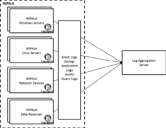
HHPC 10061
6-9
Verify that this is the correct version before use.
Figure 6.2.2.1-1 IMPALA Log aggregation process
Figure 6.2.2.1-1 is a high-level depiction of the various components of the IMPALA platform and a
sampling of the logs they forward to the log aggregation server. Log aggregation will be configured on
each application host server as well as within applications such as Cloudera, which supports the
forwarding of logs. The logs will be used primarily for auditing.
6.2.2.2 Health and Availability Monitoring
The IMPALA platform SNMP traps will be configured to forward metrics about the health of each server
and application within the IMPALA rack to SolarWinds. SolarWinds is the network and application
monitoring tool provided by the MEME infrastructure team. Health information reported about the
IMPALA platform will include performance data on CPU, memory, disk and network bandwidth
utilization. These traps will utilize the SolarWinds agents for communication with SolarWinds.
Availability status of the IMPALA platform will also be supported by reporting uptime information on
each server through SNMP to SolarWinds. For reachability, the servers within the IMPALA platform will
be configured not to block ICMP traffic but relay on the MEME.
The IMPALA data reservoir, built on the Cloudera Enterprise Data Hub (EDH) Hadoop technology,
provides visibility into the health of the data reservoir cluster through the Cloudera Manager
component. This component will also be configured to send SNMP traps to a trap collector or
monitoring tool such as SolarWinds. Cloudera Manager is also used by the Administrator to determine
the status and health of analytic jobs running within the IMPALA data reservoir. Information on how to
configure the data reservoir to report health information to a 3
rd
party monitoring tool is provided in
the Cloudera Administrator guide.
HHPC 10061
6-10
Verify that this is the correct version before use.
The above configuration will ensure that the IMPALA platform’s health is monitored and issue
resolution is proactive instead of reactive.
6.2.3 System Patching and Updates
The IMPALA platform has many components and services that enable its operation. These components
and services rely on specific OS configurations that affect their functionality. The installation and
administration guide provided with IMPALA platform details configuration parameters for each
component/service. It is important to note that System OS patching and updates is process oriented
and highly dependent on advancement in releases by COTS vendors.
System OS patches will be applied by the MEME network team and should be planned during
maintenance windows. To patch the windows based systems within the IMPALA platform, the MEME
network team will use Desktop Central. Patching of the Linux-based systems is a manual process that
involves downloading the Red Hat Package Manager (RPM) updates to each Linux server and then
deploying the patch using yum. This process is manual to ensure that packages do not interfere with
the operation of the applications and because the IMPALA platform has no internet access. Each
system should be backed up prior to applying a patch to ensure rollback in the event of a failure to the
applications hosted on the systems. For example, a Linux OS patch may update the kernel. This could
break the application if there are incompatibilities with the application in the new kernel. System
patches (OS) will be scheduled separately from application updates to more easily determine the source
of any faults or failures. Application update instruction with release notes are provided by the
application partners. Application configuration files should be backed up before applying updates.
6.2.4 Backup & Recovery
6.2.4.1 Data Backup Schedule
The IMPALA platform will leverage the NetBackup software used by the MEME Infrastructure team to
enable weekly full backup and daily incremental backup schedule. Incremental backups will be retained
for at least two weeks and Full backups retained for two weeks.
The storage unit has a 60TB capacity; 20TB will be used to support the virtual infrastructure and
ensuring high availability for the virtual machines. The 40TB left will be devoted to the backup process.
Figure 6.2.4.1-1 is a depiction of the backup schedule as well as the feasible retention and growth rate.
The first line of colored blocks indicates the type of backup, numbered incrementally. The blue blocks
indicate full backups and the green incremental. The second line shows the purging cycle for the
indicated backup (after two weeks). Red blocks indicate the deletion of the corresponding full backup
and the brown deletion of incremental backups. The third line shows the size of the backup, again, blue
for full and green for incremental. The fourth line (yellow) shows the cumulative size of the daily
backups on storage. The first full backup is 3TB, the next six incremental backups are 0.1TB in size, and
the eighth, is the cumulative size of the previous seven (7) plus the size of the new full backup (0.6TB
bigger than the previous full). At the end of the second week, we continue the same pattern and begin
to delete full and incremental backups from two weeks ago. This is reflected in the cumulative size of
30TB after 90 days. At the end of this period, the decision must be made on how much data to retain in
order to extend the life of the storage unit or if to leverage external storage devices like tape.

HHPC 10061
6-11
Verify that this is the correct version before use.
Full backup
Incremental backup
Delete Full backup
Summary
• Take daily incremental backups from Mon – Sat
• Take weekly full backups on Sun
• Keep daily incremental backups for 2 weeks
• Keep weekly full backups for 2 weeks
• At 3 TB of full backup size and 0.1 of incremental backup, the capacity needed at 90 days is approx. 30 TB
S M T W T F S S M T W T F S S M T W T F S S M T W T F S S M T W T F S S M T W T F S S M T W T F S S M T W T F S S M T W T F S S M T W T F S S M T W T F S S M T W T F S S M T W T F S
1 2 3 4 5 6 7 8 9 10 11 12 13 14 15 16 17 18 19 20 21 22 23 24 25 26 27 28 29 30 31 32 33 34 35 36 37 38 39 40 41 42 43 44 45 46 47 48 49 50 51 52 53 54 55 56 57 58 59 60 61 62 63 64 65 66 67 68 69 70 71 72 73 74 75 76 77 78 79 80 81 82 83 84 85 86 87 88 89 90 91
1 2 3 4 5 6 7 8 9 10 11 12 13 14 15 16 17 18 19 20 21 22 23 24 25 26 27 28 29 30 31 32 33 34 35 36 37 38 39 40 41 42 43 44 45 46 47 48 49 50 51 52 53 54 55 56 57 58 59 60 61 62 63 64 65 66 67 68 69 70 71 72 73 74 75 76 77
3.0 0.1 0.1 0.1 0.1 0.1 0.1 3.6 0.1 0.1 0.1 0.1 0.1 0.1 4.2 0.1 0.1 0.1 0.1 0.1 0.1 4.8 0.1 0.1 0.1 0.1 0.1 0.1 5.4 0.1 0.1 0.1 0.1 0.1 0.1 6.0 0.1 0.1 0.1 0.1 0.1 0.1 6.6 0.1 0.1 0.1 0.1 0.1 0.1 7.2 0.1 0.1 0.1 0.1 0.1 0.1 7.8 0.1 0.1 0.1 0.1 0.1 0.1 8.4 0.1 0.1 0.1 0.1 0.1 0.1 9.0 0.1 0.1 0.1 0.1 0.1 0.1 9.6 0.1 0.1 0.1 0.1 0.1 0.1 10.2 0.1 0.1 0.1 0.1 0.1 0.1 10.8
3 3.1 3.2 3.3 3.4 3.5 3.6 7.2 7.3 7.4 7.5 7.6 7.7 7.8 9.0 9.1 9.2 9.3 9.4 9.5 9.6 10.8 10.9 11.0 11.1 11.2 11.3 11.4 12.6 12.7 12.8 12.9 13.0 13.1 13.2 14.4 14.5 14.6 14.7 14.8 14.9 15.0 16.2 16.3 16.4 16.5 16.6 16.7 16.8
18.0 18.1 18.2 18.3 18.4 18.5 18.6 19.8 19.9 20.0 20.1 20.2 20.3 20.4 21.6 21.7 21.8 21.9 22.0 22.1 22.2 23.4 23.5 23.6 23.7 23.8 23.9 24.0 25.2 25.3 25.4 25.5 25.6 25.7 25.8 27.0 27.1 27.2 27.3 27.4 27.5 27.6 28.8
Week 13
Week 7
Week 8
Week 9
Week 10
Week 11
Week 12
Week 1
Week 2
Week 3
Week 4
Week 5
Week 6
Delete Incremental backup
Figure 6.2.4.1-1 IMPALA Backup Schedule – Short Term
HHPC 10061
6-12
Verify that this is the correct version before use.
6.2.4.2 Virtual Machine (VM) Backup
VMs will be backed up on a regular schedule according to HH&P IT recommended best practices for the
existing virtual infrastructure.

HHPC 10061
7-1
Verify that this is the correct version before use.
7.0 DETAILED DESIGN
7.1 INFRASTRUCTURE DETAILED DESIGN
The IMPALA platform’s design is a single rack appliance with redundant power, network and data store.
Figure 7.1-1 is a diagram of the IMPALA Platform’s hardware inventory and power requirements. Tables
7.1-1 through 7.1-3 provide details of the individual system’s components. The IMPALA rack consists of
three (3) application hosts, an Enterprise Data Hub (2 master nodes and 4 data nodes), four switches,
and an iSCSI storage node. The following sub sections detail the contents of the IMPALA rack and how
they connect with the MEME network.
Figure 7.1-1 IMPALA Platform and Hardware Power Details

HHPC 10061
7-2
Verify that this is the correct version before use.
7.1.1 Application Nodes
The application nodes are running a virtual infrastructure. The virtual infrastructure includes physical
devices and software. The physical devices are three (3) servers as virtual hosts and a shared Network
Attached Storage (NAS) device. The virtualization software is VMWare vSphere Enterprise Plus. The
table below describes the components of the virtual infrastructure software and their functions.
TABLE 7.1.1-1 IMPALA VIRTUAL INFRASTRUCTURE SOFTWARE AND FUNCTIONS
Component Function
vCenter Server
A centralized management application for the VMWare virtualization
platform
ESXi Host
An operating system-independent hypervisor based on the VMKernel
Operating system interfacing with agents that run atop it. It is the
exclusive hypervisor for VMWare
The IMPALA platform leverages virtualization for deploying virtual servers that host the applications.
Each application node is configured as an ESXi host, an operating system-independent hypervisor. The
IMPALA application nodes provide the compute power for the components within the IMPALA
platform. These components are the COTS (Commercial-Off-The-Shelf) products that have been
integrated to meet the requirements of big data analytics. These components and their functions are
defined in the table below.
TABLE 7.1.1-2 IMPALA APPLICATIONS AND FUNCTIONS
Component Functions User Role
Trifacta
This visual data ingest and transformation tool provides an
intuitive interface that enables users to quickly cleanse,
transform, prepare and profile data without the need for
custom programming.
Internal User
Pentaho Data
Integrator
Component allows HH&P IT users to develop Extract-
Transform-Load (ETL) job to copy data from data sources such
as the EMR or the LSAH into the IMPALA data reservoir.
IT User
Alpine Chorus
Allows users to create local workspaces, workflows, select and
combine data sources, perform analytics, and share their
work. Alpine Chorus visual analytics natively supports
collaboration, model version control and importing data from
various data sources, including Hadoop and structured
databases at scale. The analytics engine features a drag-and-
drop interface to connect data to computational operators
and comes with a rich set of analytic tools including
classification, regression, decision trees, time series analysis,
and more.
Internal User
Waterline Data
Automatically discovers meta-data, categorizes data sets and
IT User

HHPC 10061
7-3
Verify that this is the correct version before use.
Component Functions User Role
creates a data inventory. Tracks the lineage of all data ingest
through analysis. Data Profiling improves search capability
through data cataloging and tagging that captures source,
inputs, context, and parameters.
Tableau Desktop
Provides intuitive, visual-based data discovery capabilities.
Also provides advanced business intelligence capabilities,
dashboards, and reports.
Internal User
Centrifuge
A big data discovery technology that provides the power and
flexibility to connect, visualize and collaborate. It combines
sophisticated link-analysis, interactive visualizations and
discovery features to dramatically simplify data pattern and
connection recognition
Internal User
Cloudera Data
Navigator
A complete data governance manager for Apache Hadoop,
which provides Data Life Cycle Management, Backup, and
capability to encrypt data at rest.
IT User
Kerberos
Kerberos is the foundation of securing IMPALA Platform
Hadoop cluster and is used to authenticate user’s access to
Cloudera Hadoop resources
IT User
IMPALA Portal/
Identify
Management
Single Landing Page that integrates the user interface to all
IMPALA Platform dashboards, reports and User Facing tools.
Hosted by HHP IT and fully integrated with NAMS/Active
Directory for user Authentication and Authorization.
Internal User
As depicted in Figure 4.4-1 in section 4.4, each application node is fitted with one iDRAC port and five
NICS; two 1Gbe dedicated to the user network, two 10Gbe dedicated to intra-rack or internal cluster
communications and one 1Gbe dedicated to management. For the user network, two 1Gbe NICs
connect to the two 1Gbe switches and are configured as a NIC team for redundancy. End users will
communicate with the applications over this user network, after going through the MEME VPN and
firewall. The application nodes will communicate with other nodes within the IMPALA rack through the
two (2) 10Gbe ports also configured as a NIC team and connected to the two 10Gbe switches.
The applications within the application nodes are the primary means for end users and administrators
to interact with the IMPALA Enterprise Data Hub, also known as the IMPALA Data Reservoir (see 7.2
below). The specifications of the IMPALA platform’s application nodes are listed in the table below:

HHPC 10061
7-4
Verify that this is the correct version before use.
TABLE 7.1.1-3 IMPALA APPLICATION NODE CONFIGURATION
Component
Specifications
PowerEdge R730xd
PowerEdge R730xd Server
Chassis Configuration
Chassis with up to 12, 3.5" Hard Drives and 2, 2.5" Flex Bay Hard
Drives
Processor
Intel® Xeon® E5-2630 v4 2.2GHz,25M Cache,8.0 GT/s
QPI,Turbo,HT,10C/20T (85W) Max Mem 2133MHz
Additional Processor
Intel® Xeon® E5-2630 v4 2.2GHz,25M Cache,8.0 GT/s
QPI,Turbo,HT,10C/20T (85W) Max Mem 2133MHz
Memory Capacity
(18) 32GB RDIMM, 2400MT/s, Dual Rank, x4 Data Width
RAID Configuration
RAID 1+RAID 5 for H330/H730/H730P (2 + 3-22 HDDs or SSDs)
RAID Controller
PERC H730 RAID Controller, 1GB NV Cache
Hard Drives
(2) 400GB Solid State Drive SAS Mix Use MLC 12Gbps 2.5in Flex
Bay Drive
Hard Drives
(5) 4TB 7.2K RPM NLSAS 12Gbps 512n 3.5in Hot-plug Hard Drive
Additional Network Cards
Intel X520 DP 10Gb DA/SFP+ Server Adapter
Embedded Systems Management
iDRAC8 Enterprise, integrated Dell Remote Access Controller,
Enterprise
Power Supply
Dual, Hot-plug, Redundant Power Supply (1+1), 750W
Power Cords
(2) NEMA 5-15P to C13 Wall Plug, 125 Volt, 15 AMP, 10 Feet (3m),
Power Cord, North America
Network Daughter Card
Intel X520 DP 10Gb DA/SFP+, + I350 DP 1Gb Ethernet, Network
Daughter Card
Hardware Support Services
3Yr Basic HW Warranty Repair, 5x10 NBD Onsite
7.1.2 Enterprise Data Hub
An Enterprise Data Hub (EDH) is a big data management model that uses a Hadoop platform as the
central data repository. The goal of an enterprise data hub is to provide an organization with a
centralized, unified data reservoir that can quickly provide diverse business users with the information
they need to do their jobs; to quickly gain value from that data through a collection of frameworks that
span data processing, interactive analytics, and real-time serving applications. The IMPALA Enterprise
Data Hub (EDH) leverages Cloudera Hadoop as the data reservoir for the IMPALA platform. As stated in
section 4, the data reservoir is configured to be highly redundant. The enterprise data hub also
supports all the functions of executing jobs in parallel within the IMPALA platform. Users access the
functionality of the data reservoir through the applications within the application nodes. Physically, the
IMPALA EDH consists of two (2) master nodes and four (4) data nodes. These nodes are deployed on
physical servers. The EDH nodes are deployed in a cluster that leverages the resources (CPU and RAM)
of all nodes.

HHPC 10061
7-5
Verify that this is the correct version before use.
Figure 7.1.2-1 Enterprise Data Hub Service Layout
7.1.2.1 Master Nodes
The master nodes are deployed in an HA (High Availability) configuration with one node serving the role
of the Active Name node and the other as the Standby Name Node. Name nodes assist in tracking
resources being used by the data nodes as well as managing the execution of jobs in parallel within the
IMPALA EDH or Data Reservoir.
The master nodes communicate with the rest of the nodes within the IMPALA rack via the 10Gbe intra
rack network described in section 4. They also serve as the gateway for the applications to
communicate with the data nodes. Finally, the master nodes host the services that enable
administrators to interact directly with the data reservoir. End Users will have no direct access to the
Data Reservoir; instead, end-users will access functionality and data through the application nodes and
the applications that reside there. Administrators will have SSH (secure shell) access to the data
reservoir to perform administrative tasks over the management network. They will also have GUI based
tools dedicated to performing administrative tasks.
The table below describes the hardware specifications of the master nodes:
TABLE 7.1.2.1-1 IMPALA MASTER NODE CONFIGURATION
Component Specifications
PowerEdge R730xd
PowerEdge R730xd Server
Chassis Configuration
Chassis with up to 12, 3.5" Hard Drives and 2, 2.5" Flex Bay
Hard Drives
Processor
Intel® Xeon® E5-2630 v4 2.2GHz,25M Cache,8.0 GT/s
QPI,Turbo,HT,10C/20T (85W) Max Mem 2133MHz
Additional Processor
Intel® Xeon® E5-2630 v4 2.2GHz,25M Cache,8.0 GT/s
QPI,Turbo,HT,10C/20T (85W) Max Mem 2133MHz
Memory DIMM Type and Speed
2400MT/s RDIMMs

HHPC 10061
7-6
Verify that this is the correct version before use.
Component Specifications
Memory Capacity
32GB RDIMM, 2400MT/s, Dual Rank, x4 Data Width
RAID Configuration
RAID 1 for H330/H730/H730P (2 + 3-22 HDDs or SSDs)
RAID Controller
PERC H730 RAID Controller, 1GB NV Cache
Hard Drives
400GB Solid State Drive SAS Mix Use MLC 12Gbps 2.5in Flex
Bay Drive
Hard Drives
4TB 7.2K RPM NLSAS 12Gbps 512n 3.5in Hot-plug Hard Drive
Additional Network Cards
Intel X520 DP 10Gb DA/SFP+ Server Adapter
Embedded Systems Management
iDRAC8 Enterprise, integrated Dell Remote Access Controller,
Enterprise
Power Management BIOS Settings
Performance BIOS Setting
Power Supply
Dual, Hot-plug, Redundant Power Supply (1+1), 750W
System Documentation
Electronic System Documentation and OpenManage DVD Kit
PCIe Riser
Risers with up to 1, x8 PCIe Slots + 2, x16 PCIe Slots
Network Daughter Card
Intel X520 DP 10Gb DA/SFP+, + I350 DP 1Gb Ethernet,
Network Daughter Card
Hardware Support Services
3Yr Basic HW Warranty Repair, 5x10 NBD Onsite
7.1.2.2 Data Nodes
The IMPALA Platform data nodes are the other part of the EDH or Data Reservoir. The IMPALA platform
consists of four (4) data nodes that scale by adding additional data nodes. Each data node performs the
functions of storing data as well as executing requests against data in parallel. Every block of data
within the data node is replicated 3 times for redundancy to ensure data is not lost. The end users have
no direct access to the data nodes; their access to the data is through the application nodes. The table
below depicts the specification of a data node.

HHPC 10061
7-7
Verify that this is the correct version before use.
TABLE 7.1.2.2-1 IMPALA DATA NODE CONFIGURATION
Component
Specifications
PowerEdge R730xd
PowerEdge R730xd Server
Processor
Intel® Xeon® E5-2630 v4 2.2GHz,25M Cache,8.0 GT/s
QPI,Turbo,HT,10C/20T (85W) Max Mem 2133MHz
Additional Processor
Intel® Xeon® E5-2630 v4 2.2GHz,25M Cache,8.0 GT/s
QPI,Turbo,HT,10C/20T (85W) Max Mem 2133MHz
Memory Configuration Type
Performance Optimized
Memory Capacity
32GB RDIMM, 2400MT/s, Dual Rank, x4 Data Width
RAID Configuration
RAID 1+JBOD for H330/H730/H730P (2 + 3-22 HDDs or SSDs)
RAID Controller
PERC H730 RAID Controller, 1GB NV Cache
Hard Drives
4TB 7.2K RPM NLSAS 12Gbps 512n 3.5in Hot-plug Hard Drive
Additional Network Cards
Intel X520 DP 10Gb DA/SFP+ Server Adapter
Embedded Systems
Management
iDRAC8 Enterprise, integrated Dell Remote Access Controller,
Enterprise
Power Supply
Dual, Hot-plug, Redundant Power Supply (1+1), 750W
PCIe Riser
Risers with up to 1, x8 PCIe Slots + 2, x16 PCIe Slots
Network Daughter Card
Intel X520 DP 10Gb DA/SFP+, + I350 DP 1Gb Ethernet, Network
Daughter Card
Hardware Support Services
3Yr Basic HW Warranty Repair, 5x10 NBD Onsite
7.1.3 Storage Node
The IMPALA Platform has an iSCSI NAS device that serves two functions: hosting configuration files and
disks for virtual machines and temporary backup for data that is within the data reservoir. The storage
node is only accessible from within the IMPALA rack. The table below depicts the specification for the
iSCSI storage device.
TABLE 7.1.3-1 IMPALA STORAGE NODE CONFIGURATION
Component
Specifications
EqualLogic PS4210E
EqualLogic PS4210E, Intel®Xeon®E5-2630v3, 2.4GHz, 32GB
Mem
RAID Configuration
RAID 6 for H330/H730/H730P (4-12 HDDs)
Hard Drives
(12) 6TB 7.2K SAS, 12Gb, 3.5
Power Supply
Dual, Hot-plug, Redundant Power Supply (1+1), 750W
Network Daughter Card
Dual Controllers, 10Gb, High Availability with Failover
Hardware Support Services
3Yr Basic Hardware Warranty Repair:
ProSupport: 7x24 HW / SW Tech Support and Assistance, 3
Year

HHPC 10061
7-8
Verify that this is the correct version before use.
7.1.4 System Software Specifications
This section provides a detailed description for each system software service. Before delving into the
specific tools, we will briefly discuss the operating systems for IMPALA Platform. On the client side, the
IMPALA platform will support clients running most operating systems including Windows, Linux and
Macs. The table below depicts the server-side operating systems and the counts.
TABLE 7.1.4-1 SERVER-SIDE OPERATING SYSTEMS AND COUNT
Component
Operating Systems
Number of Physical Servers
Number of Virtual
Servers
Server Side
RedHat Enterprise Linux
Version 6.7
6
16
7.1.5 Power consumption
The following two tables detail the power consumption for each component of the IMPALA platform.
TABLE 7.1.5-1 POWER CONSUMPTION
System Name
Operating
System
System
Function
Total Memory
Disk
Configuration
RAID
Total Disk
Input Power
(Watts)
Input Power
(BTU/h)
Power Supply
Capacity
(Watts)
Power Supply
Capacity
(BTU/h)
FS1048D-01
N/A
10Gb Switch
N/A
N/A
N/A
N/A
254.1 W
866.9 btu/h
460 W
1569.6 btu/h
FS1048D-02
N/A
10Gb Switch
N/A
N/A
N/A
N/A
254.1 W
866.9 btu/h
460 W
1569.6 btu/h
FS448D-01
N/A
1Gb Switch
N/A
N/A
N/A
N/A
65 W
221.8 btu/h
N/A
N/A
FS448D-02
N/A
1Gb Switch
N/A
N/A
N/A
N/A
65 W
221.8 btu/h
N/A
N/A
Master Node 1
RedHat 6.7
Active Name Node
256GB
5 x 4TB
6
12TB
368 W
1255.7 btu/h
750 W
2559.1 btu/h
Master Node 2
RedHat 6.7
Standby Name Node
256GB
5 x 4TB
6
12TB
368 W
1255.7 btu/h
750 W
2559.1 btu/h
RedHat Node 1
RedHat 6.7
App Host
512GB
5 x 4TB
6
12TB
392 W
1337.6 btu/h
750 W
2559.1 btu/h
RedHat Node 2
RedHat 6.7
App Host
512GB
5 x 4TB
6
12TB
392 W
1337.6 btu/h
750 W
2559.1 btu/h
RedHat Node 3
RedHat 6.7
App Host
512GB
5 x 4TB
6
12TB
392 W
1337.6 btu/h
750 W
2559.1 btu/h
Datanode04
RedHat 6.7
Hadoop Data
256GB
18 x 2TB
N\A
36TB
431 W
1470.6 btu/h
750 W
2559.1 btu/h
Datanode03
RedHat 6.7
Hadoop Data
256GB
18 x 2TB
N\A
36TB
431 W
1470.6 btu/h
750 W
2559.1 btu/h
Datanode02
RedHat 6.7
Hadoop Data
256GB
18 x 2TB
N\A
36TB
431 W
1470.6 btu/h
750 W
2559.1 btu/h
Datanode01
RedHat 6.7
Hadoop Data
256GB
18 x 2TB
N\A
36TB
431 W
1470.6 btu/h
750 W
2559.1 btu/h
EqualLogic
PS4210E
Windows Storage
Network Storage
12 x 6TB
6
48TB
327.2 W
116.3 btu/h
700 W
2446.1 btu/h

HHPC 10061
7-9
Verify that this is the correct version before use.
TABLE 7.1.5-2 POWER CONSUMPTION (CONTINUED)
System Name
Maximum
Potential Power
(Watts)
Maximum
Potential
Power
(BTU/h)
Input
Current
(A)
Sound
Power Level
(bels)
Airflow
Rate (CFM)
Airflow
Rate (l/s)
Air Temp
Rise (°C)
Air Temp
Rise (°F)
Weight
(lbs)
Weight
(Kg)
FS1048D-01-
01
420 W
N/A
1.2 A
N/A
N/A
N/A
N/A
N/A
19.40 lbs
8.8 Kg
FS-1048D-02
420 W
N/A
1.2 A
N/A
N/A
N/A
N/A
N/A
19.40 lbs
8.8 Kg
FS-448D-01
N/A
N/A
1.34 A
N/A
N/A
N/A
N/A
N/A
8.2 lbs
3.7 Kg
FS448D-02
N/A
N/A
1.34 A
N/A
N/A
N/A
N/A
N/A
8.2 lbs
3.7 Kg
Master Node 1
594.1 W
2027. btu/h
1.7 A
6.1 bels
27.5 CFM
13 l/s
24.1 °C
43.4 °F
71.7 lbs
32.5 Kg
Master Node 2
594.1 W
2027. btu/h
1.7 A
6.1 bels
27.5 CFM
13 l/s
24.1 °C
43.4 °F
71.7 lbs
32.5 Kg
RedHat Node
1
630.2 W
2150.3 btu/h
1.8 A
6.2 bels
28.7 CFM
13.6 l/s
24.6 °C
44.2 °F
71.7 lbs
32.5 Kg
RedHat Node
2
630.2 W
2150.3 btu/h
1.8 A
6.2 bels
28.7 CFM
13.6 l/s
24.6 °C
44.2 °F
71.7 lbs
32.5 Kg
RedHat Node
3
630.2 W
2150.3 btu/h
1.8 A
6.2 bels
28.7 CFM
13.6 l/s
24.6 °C
44.2 °F
71.7 lbs
32.5 Kg
Datanode04
658.8 W
2248 btu/h
2 A
6.5 bels
25 CFM
11.8 l/s
31 °C
55.9 °F
65 lbs
29.5 Kg
Datanode03
658.8 W
2249 btu/h
2 A
6.5 bels
25 CFM
11.8 l/s
32 °C
55.9 °F
65 lbs
29.5 Kg
Datanode02
658.8 W
2250 btu/h
2 A
6.5 bels
25 CFM
11.8 l/s
33 °C
55.9 °F
65 lbs
29.5 Kg
Datanode01
658.8 W
2251 btu/h
2 A
6.5 bels
25 CFM
11.8 l/s
34 °C
55.9 °F
65 lbs
29.5 Kg
Equal Logic
PS4210E
408.4 W
1393.5 btu/h
1.5 A
5.4 bells
19.3 CFM
9.1 l/s
22.8 °C
41 °F
60.84 lbs
27.6 Kg
7.2 SECURITY DETAILED DESIGN
This section describes the Security Detailed Design. As noted in section 4, Security for the IMPALA
platform is designed to protect the data at five discrete layers Perimeter Security, Authentication,
Authorization, Encryption and Policy. Within the IMPALA platform these five (5) layers are depicted as
modules, table 7.2-1 below is a mapping of the technical security layers to the IMPALA security
modules.
TABLE 7.2-1 PROTECTION POINT TO IMPALA MODULE MAPPING
Protection Layers
IMPALA Security
Module
IMPALA Security
Sub Modules
MEME Support
Perimeter
N/A
N/A
MEME-Firewall,
MEME-VPN, SSL
Certificate
Authentication
IMPALA Authentication
Kerberos
Active Directory,
Launchpad
Authorization
IMPALA RBAC
Sentry, Kerberos
Active Directory, NAMS

HHPC 10061
7-10
Verify that this is the correct version before use.
Protection Layers
IMPALA Security
Module
IMPALA Security
Sub Modules
MEME Support
Encryption
IMPALA Encryption
Navigator Encrypt,
Key Management
Server (KMS), Key
Trustee Server (KTS),
Hardware Security
Module (HSM)
Policy
IMPALA Auditing
Navigator Audit,
Navigator Lineage,
Waterline
CIS Benchmark,
Vulnerability
management (MVM),
Anti-virus and
Application/Memory
protection tool
(TrendMicro & EMET),
Log Aggregation
(Splunk),
inventory/system
management (Dell
KACE)
The following diagram depicts how the IMPALA security Modules fit in the MEME Network.
Figure 7.2-1 IMPALA Security Overview

HHPC 10061
7-11
Verify that this is the correct version before use.
All the security components are addressed in the sections that follow as well as how they communicate
with the data reservoir.
7.2.1 Perimeter Security
Figure 7.2.1-1 Perimeter Security
The IMPALA platform relies on the MEME environment and the JSC network to provide perimeter
security. The MEME firewall prevents unauthorized access from outside to services in the MEME
environment. Requests for access to the IMPALA environment will come through the NASA Access
Management System (NAMS). Requests will be forwarded to the IMPALA administrators to ensure that
the user is provisioned in the correct groups and roles as defined in the data governance guide.
End Users leverage the JSC NDC Active Directory domain for authentication. An end user will
authenticate using a PIV card through the NASA Launchpad interface. Before authentication the user
must first establish a Virtual Private Network (VPN) connection with the MEME environment to gain
access to the IMPALA platform portal page (Figure 4.5-2 depicts this process).
7.2.2 IMPALA Authentication Module
The IMPALA authentication module performs authentication at the service/component level and at the
end user level. It is also the integration point between the NASA Active directory domain and the
IMPALA platform. Within the IMPALA platform, there are three types of accounts: user, component
and service.
The user accounts are the end-user accounts that authenticate into the IMPALA platform and utilize its
services. User accounts must first be registered in the NASA Active directory domain (NDC). The NASA
environment is transitioning to the use of PIV cards, which enable certificate based two-factor

HHPC 10061
7-12
Verify that this is the correct version before use.
authentication against the NDC. These users through web interfaces access the IMPALA platform
components. The IMPALA web interfaces will be front–ended by the NASA Launchpad application to
ensure that users can authenticate using their PIV cards. Finally, user profiles are created within the
IMPALA components during the user registration process. These profiles enable fine-grained privileges
within each component. These privileges are defined by roles within each component. Section 7.3.2
highlights these component roles.
Component accounts are accounts or principals defined within the IMPALA Key Distribution Center
(KDC). The KDC is described in detail later in this section. These accounts are created when the
components are installed and they are local to the IMPALA platform. Components provide access to
functionality within the IMPALA platform and serves as the only access to the IMPALA data reservoir.
Every component authenticates against the IMPALA KDC to identify itself as an authorized user to
execute jobs within the IMPALA data reservoir.
The service accounts are accounts created automatically during the deployment of the IMPALA data
reservoir. These accounts are also defined within the KDC to ensure that each service must first
authenticate before performing actions like assigning resources to execute jobs within the IMPALA data
reservoir.
The IMPALA data reservoir is configured to work with a Kerberos Key Distribution Center (KDC). The
KDC serves as the internal domain controller for the IMPALA data reservoir. All services and
components within the IMPALA data reservoir (Enterprise Data Hub - EDH) are registered within the
KDC. The KDC enables all component and service accounts to authenticate within the IMPALA data
reservoir using generated keytabs (keytabs are described below).
A one-way cross realm trust is setup between the NASA NDC domain and the IMPALA data reservoir
KDC. This trust ensures that only user accounts that have been registered within the NDC can access
services offered in the IMPALA data reservoir through the IMPALA components. Once an end user
authenticates into an IMPALA component and the profile is validated within the component, the
component account serves as a delegate for the user into the IMPALA data reservoir.
Figure 7.2.2-1 IMPALA Authentication Flow Diagram

HHPC 10061
7-13
Verify that this is the correct version before use.
Figure 7.2.2-1 above shows how Kerberos works with the Perimeter Security discussed earlier to
provide authentication for all users and services in the IMPALA platform. Before we delve deeper into
the IMPALA authentication Module, we begin by introducing some terminology in the Table 7.2.2-1
below.
TABLE 7.2.2-1 IMPALA AUTHENTICATION SECURITY MODULE TERMINOLOGIES
Terminology Description
Keytab
A keytab is a file containing pairs of Kerberos principals and encrypted keys
that are derived from the Kerberos password. IMPALA applications use
keytabs to authenticate to the IMPALA Data Reservoir services without
requiring human interaction. The keytabs are protected and only allow
access to services and never allow access to data.
Kerberos Principal
A Kerberos principal is a unique identity to which Kerberos can assign
tickets. Traditionally, a principal is divided into three parts: the primary,
the instance, and the realm. The format of a typical Kerberos V5 principal
is primary/instance@REALM. Service principals are used for accessing
services (including servers) in the IMPALA platform and User principals are
for user access.
Primary
The primary is the first part of the Kerberos principal. In the case of a user,
it's the same as your username. For a host, the primary is the word “host”.
instance
The instance is an optional string that qualifies the primary. The instance is
separated from the primary by a slash (/). In the case of a user, the instance
is usually null, but a user might also have an additional principal, with an
instance called admin, which he/she uses for administration. The
principal
jennife[email protected].GOV is completely separate from the
principal jennifer/[email protected], with a separate password, and
separate permissions. In the case of a host, the instance is the fully qualified
hostname, e.g., “host/server.ndc.nasa.gov”.
Realm
The realm is your Kerberos realm, which, in most cases, is your domain
name, in upper-case letters. For example, the machine server.ndc.nasa.gov
would be in the realm “NDC.NASA.GOV”.
The IMPALA authentication module is the foundational building block for IMPALA Security and all other
submodules leverage it to function. The IMPALA authentication module is also the key player that
controls access to other components.
Kerberos internally uses a ticketing system that employs security keys. To achieve this, it has a Key
Distribution Center (KDC) that is responsible for managing and distributing credentials. To avoid
downtimes, we deploy Kerberos in a highly available mode by configuring a failover Slave KDC. The
following section details how Kerberos is configured and how it works.
• Both the Master and Slave KDC servers define a distinct Kerberos realm and are deployed
internally to the IMPALA platform.

HHPC 10061
7-14
Verify that this is the correct version before use.
• All servers within the IMPALA platform are configured with both the Kerberos realm (local to
IMPALA) and NASA AD domain. The default realm is set to be the local IMPALA Kerberos realm.
For example the Administrator could choose the local realm to be IMPALA.NDC.NASA.GOV and
the NASA AD could have a realm of NDC.NASA.GOV
• Service principals (service accounts mentioned above) are created in the local IMPALA KDC
under the IMPALA Kerberos realm.
• A one-way, cross-realm trust must be set up from the IMPALA Kerberos realm to the central
NASA AD domain containing the user principals (users) that require access to the data reservoir.
As a result, there is no need to create user principals in the local realm.
With the Modular Authentication design discussed above, Kerberos authentication can be configured
using the local IMPALA KDC independently of integrating with Active Directory. An advantage of this is
that the local IMPALA KDC serves as a shield for the central NASA Active Directory from the many hosts
and services in the IMPALA system since all service requests are granted locally instead of going out to
the NASA AD on each call.
It should be noted that service restarts in a large cluster that are not shielded as described above create
many simultaneous authentication requests which impact the NASA AD service.
7.2.3 IMPALA RBAC Module
In IMPALA, there are two classes of roles: component (or application) roles and data roles.
The component (or application) roles are predefined within the applications. These roles encapsulate
the privileges of a user within the component. Table 7.2.3-1 is a listing of the IMPALA components that
have defined roles and the privileges of those roles. Users are assigned to one of these roles when
registered within each application/component.
TABLE 7.2.3-1 IMPALA COMPONENT ROLES AND PRIVILEGES
Component Tool Roles Function
Alpine
Administrator
Setup up and assign users to profiles.
Establish/Create data source connections
Collaborator
View or execute created workflows. Create
comments
Developer
Create workflows. Share out workspaces
Trifacta
Data Admin
Create user profiles
Wrangler
Create transformation projects
Waterlinedata
Administrator
Create User Profiles
Data Steward
Create tagging profiles

HHPC 10061
7-15
Verify that this is the correct version before use.
Component Tool Roles Function
Annotator
Tag associations: Create, approve, and reject tag
associations (any tag domain)
Origins : Create, update, and remove origins
Lineage relationships : Create, approve, and reject
lineage relationships
Collections: Create, approve, and remove
collections
End User
Data : View authorized data
Metadata :View authorized metadata
Hive tables: Create Hive tables
Centrifuge
Administrator
Create User Profiles
Developer
Create exploration projects and visual dashboards
Pentaho Data Integrator
Administrator
Administer security
Read Content
Execute Jobs
Create Content
Power User
Read Content
Execute Jobs
Create Content
IMPALA Portal
Administrator
Administer Security: User profiles, roles etc
User
Create, Edit and View projects for analytics, search,
development of ETL etc
The data roles govern authorization to data within the IMPALA data reservoir using a method of
regulating access known as Role-Based Access Control (RBAC). In this context, access is the ability of an
individual user to perform a specific task against the data within the IMPALA data reservoir, such as
view, create, or modify a file. Apache Sentry and Record Services are the components used to enable
RBAC within the IMPALA platform. Although Record Service is still in a Beta release, the IMPALA team
has decided to use it as it best aligns with the requirements.

HHPC 10061
7-16
Verify that this is the correct version before use.
Figure 7.2.3-1 IMPALA Authorization Flow Diagram
Apache Sentry and Record Services are role-based authorization models for the IMPALA data reservoir,
offering fine-grained access to data accessible using schema. They both provide the ability to control
and enforce precise levels of privileges on data for authenticated users and IMPALA components (or
applications). It allows for the definition of authorization rules to validate access requests for resources
within the IMPALA data reservoir. The following sections discuss both Apache Sentry and Record
services in more detail.
Apache Sentry maps users and groups defined within the NDC active directory, as well as component
principals defined within the KDC, to roles within the IMPALA data reservoir. IMPALA administrators,
based on guidance from the data governance board, create the roles within the IMPALA data reservoir
and map these roles to the NDC active directory groups and component principals. Privileges to read,
write or both are granted to the individual roles for the data entities within the IMPALA platform via
policy files or directly using GRANT options within the Sentry Service.
Table 7.2.3-2 describes the Sentry components.

HHPC 10061
7-17
Verify that this is the correct version before use.
TABLE 7.2.3-2 IMPALA SENTRY COMPONENTS AND FUNCTIONS
Sentry Components Description
Sentry Server
The Sentry Remote Procedure Call (RPC) server manages the authorization
metadata. It supports interfaces to securely retrieve and manipulate the
metadata
Data Engine
The data engine loads the Sentry plugin. It intercepts all requests for
accessing data and routes them to the Sentry plugin for validation.
Sentry Plugin
The Sentry plugin runs in the data engine. It offers interfaces to
manipulate authorization metadata stored in the Sentry server, and
includes the authorization policy engine that evaluates access requests
using the authorization metadata retrieved from the server
With Sentry we gain the following RBAC (role-based access control) features for the IMPALA platform:
• Secure authorization: Sentry provides the ability to control and enforce access to data and/or
privileges on data for authenticated users.
• Fine-grained access control: Sentry provides support for fine-grained access control to data and
metadata. Sentry allows access control at the server, database, table, and view scopes at
different privilege levels including select, insert, and all — allowing administrators to use views
to restrict access to columns or rows. Administrators can also mask data within a file as
required by leveraging Sentry and views with case statements or User-Defined Functions
(UDF)s.
• Role-based authorization: Sentry supports ease of administration through role-based
authorization; you can easily grant multiple groups access to the same data at different privilege
levels. For example, for a particular data set you may give your HHPIT security team rights to
view all columns, your MEME admins rights to view only non-sensitive or non-PII (personally
identifiable information) columns. These rights also govern the ingest processing pipeline
through the user roles for inserts of new data into HDFS.
• Multi-tenant administration: Sentry allows permissions on different data sets to be delegated to
different administrators. In the case of Hive/Apache Impala, Sentry allows administration of
privileges at the level of a database/schema.
• Unified platform: Sentry provides a unified platform for securing data; it uses existing Hadoop
Kerberos security for authentication. In addition, the same Sentry policy can be enforced while
accessing data through either Hive or Impala.
Record Service maps users and groups defined within the NDC active directory, as well as component
principals defined within the KDC, to roles within the IMPALA data reservoir by leveraging the Apache
Sentry service. IMPALA administrators, based on guidance from the data governance board, create the
roles within the IMPALA data reservoir and map these roles to the NDC active directory groups and
component principals. Privileges to read, write or both are granted to the individual roles for the data
entities within the IMPALA platform using GRANT options within the Sentry Service

HHPC 10061
7-18
Verify that this is the correct version before use.
Table 7.2.3-3 describes the Record Service components.
TABLE 7.2.3-3 RECORD SERVICE COMPONENTS AND FUNCTIONS
Record Service
Components
Description
RecordServicePlanner
The Record Service Planner Generates tasks, performs authorization
checks, and handles metadata access.
RecordServiceWorker
The Record Service Worker Executes tasks, and reads and writes to the
IMPALA storage layer. It also returns rows in a canonical format.
Thrift APIs
The Thrift APIs allow connection to the two Record Service thrift services
mentioned above, Record Service Planner and Record Service Worker.
Client Integration
Libraries
This are Client integration Libraries that mostly cater for easy migration
to Record Service.
Using Record Service with Sentry provides these key benefits:
• Fine-grained security enforcement: Record Service enforces column-level permissions
(projections), row-level permissions (filtering), and data masking across the IMPALA reservoir
components.
• Performance: Record Service is designed to be on the main data access path, meaning it needs to
process every byte of data. Record Service scales horizontally to be able to run on the largest
Hadoop clusters and high efficiency. It uses the Apache Impala IO layer, which utilizes low-level
optimizations such as HDFS short-circuit reads and dynamic code generation to improve thread
throughput and reduce CPU utilization. Record Service brings these performance benefits to the
other components in Hadoop and accelerates their performance, despite adding a new layer in the
stack.
• Simplicity: Record Service provides a higher level, logical abstraction for data. Datasets can be
specified as logical names (i.e. tables or views) and Record Service returns schemed objects (in
contrast to the storage APIs that deal with paths and bytes). This means that applications built on
top of the Record Service APIs do not need to worry about differences in file formats, the
underlying storage APIs, and other low level details.
Using Record Service caveats:
• Beta Release: The current Record Service is still in Beta Release. However, the advantages of using
it are greater than the risks involved. Record Service has a huge following and is expected to be
production ready in a couple of months.

HHPC 10061
7-19
Verify that this is the correct version before use.
7.2.4 IMPALA Encryption Module
The IMPALA Encryption Module is leveraged to encrypt data at rest within the IMPALA platform using
AES-256 encryption. This ensures that any malicious access to the data does not lead to ability to read
PII information.
Figure 7.2.4-1 IMPALA Encryption Flow Diagram
The encryption module has four (4) sub components: Navigator Encrypt, Key Management Server
(KMS), Key Trustee Server (KTS) and the CPU Hardware Security Module (HSM).

HHPC 10061
7-20
Verify that this is the correct version before use.
TABLE 7.2.4-1 IMPALA ENCRYPTION COMPONENTS AND FUNCTIONS
Component Function
Navigator Encrypt
A client-side service that transparently encrypts data at rest without requiring
changes to applications and with minimal performance lag in the encryption or
decryption process. Advanced key management with Key Trustee Server and
process-based access controls in Navigator Encrypt enable organizations to meet
compliance regulations and ensure unauthorized parties or malicious actors
never gain access to encrypted data
Key Management
Server
A customized server that uses the Key Trustee Server for robust and scalable
encryption key storage and management
Key Trustee
Server
An enterprise-grade virtual safe-deposit box that stores and manages
cryptographic keys. With Key Trustee Server, encryption keys are separated
from the encrypted data, ensuring that sensitive data is protected in the event
that unauthorized users gain access to the storage media
CPU Hardware
Security Module
A service that allows Key Trustee Server to integrate with a hardware security
module (HSM). Key HSM enables Key Trustee Server to use an HSM as the root
of trust for cryptographic keys, taking advantage of Key Trustee Server’s policy-
based key and security asset management capabilities while satisfying existing
internal security requirements regarding treatment of cryptographic materials
Within the IMPALA Platform, the KMS and the KTS are configured to ensure high availability. The
Navigator Encrypt depicted above works with a Key Management Server and Key Trustee server to
manage the encryption keys transparently. For key administration, we recommend having an
administrator for the data and a security officer or administrator for the security keys to prevent
unauthorized access by super users.

HHPC 10061
7-21
Verify that this is the correct version before use.
Figure 7.2.4-2 Integration between the IMPALA Data Reservoir and the IMPALA Encryption
components
All encryptions within the IMPALA data reservoir are performed within encryption zones. An encryption
zone is a directory in HDFS with all of its contents, that is, every file and subdirectory in it, encrypted.
The files in this directory will be transparently encrypted upon write and transparently decrypted upon
read.
Each encryption zone (ez) is associated with a key (ez key) which is specified when the zone is created.
Each file within an encryption zone also has its own encryption/decryption key, called the Data
Encryption Key (DEK). These DEKs are never stored persistently unless they are encrypted with the
encryption zone's key. The encrypted DEK is known as the EDEK. The EDEK is then stored persistently as
part of the file's metadata on the Name Node which is a Master Node of the IMPALA reservoir. Since
the EDEK is encrypted, it has no value to eavesdroppers.
7.2.5 IMPALA Auditing
The IMPALA Auditing Module addresses reports on where data came from and how it is used. Internally
the module is comprised of Navigator Audit and Navigator Lineage. The module also leverages
Waterline for end-to-end data lineage.
7.2.5.1 Navigator Audit
The Navigator Audit configuration enables collection and filtering of audit events as they are added to
the IMPALA data reservoir. This is done using plug-ins provided as part of IMPALA data reservoir. The
plug-ins write the audit events to an audit log on the filesystem.
HHPC 10061
7-22
Verify that this is the correct version before use.
The IMPALA data reservoir audit components monitor the audit log files on the local filesystem and
sends these events to the Navigator Audit Server. Once the audit events are written to the audit log file,
they are guaranteed to be delivered (as long as filesystem is available) to the Navigator Audit Server.
The IMPALA data reservoir audit components keeps track of current audit event offset in the audit log
that it has successfully transmitted, so on any crash/restart it picks up the audit event from the last
successfully sent position and resumes.
This makes sure that all audit events in the IMPALA data reservoir are persisted.
7.2.5.2 Navigator Lineage
The Navigator Lineage provides an automatic collection and easy visualization of upstream and
downstream data lineage to and from the IMPALA data reservoir. For each data set in the IMPALA data
reservoir, it shows down to the column level within that data set, what the precise upstream data
sources were, the transforms performed to produce it, and the impact that data has on downstream
artifacts.
A lineage diagram is just a directed graph that depicts an entity and its relations to other entities.
With both auditing and lineage, an IMPALA security officer is able to see who had access to what
dataset and what queries or modifications they ran on the dataset. The IMPALA security officer is also
able to determine any unauthorized access to the IMPALA data reservoir datasets and take action.
To summarize, the IMPALA audit module is fundamental in understanding where the dataset came
from, which user touched the dataset, what were the security conditions on the dataset and are we still
meeting the security conditions at the end where the data rests or resides. Both Navigator Audit and
Navigator Lineage pull all audit logs and consolidates them making it easy to export to Syslog for
backup.
7.2.5.3 Waterline
The Waterline tool is also used to audit the data and provide lineage and compliments Navigator Audit
and Navigator Lineage. IMPALA extensively uses Waterline for Data Governance. We just mention that
tool here but suggest you view the Data Governance document to see other functions that the tools
provides in addition to complimenting Navigator Audit and Navigator Lineage.
7.2.5.4 Server Security Auditing
Servers within the IMPALA platform are hardened using the CIS Benchmark tool provided by the HHPIT
security team. Recommendations produced by the CIS benchmarking tool are addressed and a report is
generated for auditing purposes.
7.2.5.5 Anti-Virus Monitoring
Anti-virus agents provided by the MEME Infrastructure team are deployed on servers within the
IMPALA platform. These agents generate and publish reports to the MEME anti-virus server for
auditing.
HHPC 10061
8-1
Verify that this is the correct version before use.
8.0 INTERFACES
8.1 INBOUND INTERFACES
The following are all the inbound interfaces to the IMPALA Platform Solution.
• Electronic Medical Records (EMR): Clinical, laboratory, and medical requirements data
o Epidemiologic data is ingested from NASA internal data sources such as case
investigation files, supplemental forms, clinical data and crewmember electronic
medical records (EMR system).
• Lifetime Surveillance of Astronaut Health (LSAH): clinical, laboratory, medical requirements
data and various forms of data related to space flight
o Laboratory data such as test orders and lab results for crew members ingested from
various internal sources such as Lifetime Surveillance of Astronaut Health (LSAH)
system and existing laboratory systems
• MEDB SharePoint: medical requirements summary data stored in SharePoint
o Environmental data from internal and external investigations, operations, studies,
researchers, experiments and management activities.
o Medical data collected for a mission program (Med B) from a mission SharePoint site,
This data is primarily sourced from SharePoint lists and document libraries (PDF, Word,
and Excel documents)
• Other future inbound interfaces include Ad-hoc Datasets, VIIP, Cardio and CO2
8.2 OUTBOUND INTERFACES
The following are some of the outbound interfaces from the IMPALA Platform Solution.
• Exams and Reports for incorporation into the MASH Report
o One operational use of the IMPALA system is to locate the exams and reports produced
through clinical and lab activities. At the end of a mission, these exams and reports are
located and summarized for presentation to the crewmember and flight surgeon.
Initially, this interface will present the analysts and flight surgeon with these files in
order for offline communication with the crew member. In the future, if it is desired to
allow the crew member view access into IMPALA, these exams and reports could be
made available to them through this interface as well.
• Flight Surgeon Dashboard
o Before, during, and after a mission, clinical and lab testing must be done to fulfil MEDB
requirements. The flight surgeon dashboard is an interface where the flight surgeon can
track the status of reports and exams in the IMPALA platform, as they relate to a given
crew member’s mission and MEDB requirements.
HHPC 10061
8-2
Verify that this is the correct version before use.
• Data Catalog
o The Data Catalog is a listing of all fields in the database along with their metadata.
Users can use a web browser interface to view the Data Catalog and explore the data
that exists in the data reservoir.
• Other future outbound interfaces include
o Historical and Trend Data
o Reference and Metadata
o Audits and Exception Data
HHPC 10061
A-1
Verify that this is the correct version before use.
Appendix A Acronyms and Abbreviations
°C
degrees Celsius
°F
degrees Fahrenheit
A, AMP
Ampere
AD
Active Directory
AES
Advanced Encryption Standard
BIOS
basic input/output system
BTU
British Thermal Unit
Cardio
Cardio Ox (Defining the Relationship Between Biomarkers of
Oxidative and Inflammatory Stress and the Risk for Atherosclerosis
in Astronauts During and After Long-duration Spaceflight)
CB
Control Board
CDR
Critical Design Review
CFM
Cubic Feet per Minute
CIS
Center for Internet Security
CO2
carbon dioxide
COTS
Commercial-off-the-shelf
CPU
Central Processing Unit
CSV
comma separated value
DA
Dual Adapter
dB
decibel
DDR
Detailed Design Review
DEK
Data Encryption Key
DIMM
Dual in-line Memory Module
DNS
Domain Name Server
DOC
Microsoft Word document
DP
Dual Port
DVD
Digital Video Disk
EDEK
Encryption Data Encryption Key
EDH
Enterprise Data Hub
EMET
Enhanced Mitigation Experience Toolkit
EMR
Electronic Medical Record
ETL
Extract, Transform, Load
ez
Encryption zone
FS
Fortinet Switch
ft
feet
Gb
Gigabit
GB
Gigabyte
Gbe
Gigabit Ethernet
Gbps
Gigabits per second
GOV
Government
GT/s
Gigabit transfers/second
HHPC 10061
A-2
Verify that this is the correct version before use.
GUI
Graphical User Interface
h
hour
HA
High Availability
HDD
Hard Disc Drive
HDFS
Hadoop Distributed File System
HHP
Human Health and Performance
HHPC
Health and Human Performance Contract
HHPD
Human Health and Performance [Directorate]
HSM
Hardware Security Module
HT
Hyper Threaded
HW
Hardware
ICMP
Internet Control Message Protocol
iDRAC
Integrated Dell Remote Access Controller
IMPALA
Information Management Platform for Data Analytics and
Aggregation
in.
Inch(es)
IPTA
Initial Privacy Threshold Analysis
iSCSI
Integrated Small Computer System Interface
IRD
Information Resource Directorate
IT
Information Technology
ITAR
International Traffic in Arms Regulations
JBOD
just a bunch of drives
JDBC
Java Database Connectivity
JPEG, JPG
Joint Photographic Experts Group
JSC
Lyndon B. Johnson Space Center
JSON
JavaScript Object Notation
KDC
Key Distribution Center
kg
kilogram
KMS
Key Management Server
KTS
Key Trustee Server
l/s
liters per second
lbs
pounds
LSAH
Lifetime Surveillance of Astronaut Health
LSDA
Life Science Data Archive
m
meter
MASH
Mission Associated Summary of Health
max
maximum
MEDB
Medical Evaluation Document, Part B
MEME
Mission Extended Medical Enterprise
MHz
Megahertz
MLC
Multi-Level Cell
MS
Microsoft
HHPC 10061
A-3
Verify that this is the correct version before use.
MVM
McAfee Vulnerability Manager
N/A
Not Applicable
NACB
Network Access Control Bar
NAMS
NASA Access Management System
NAS
Network Attached Storage
NASA
National Aeronautics and Space Administration
NBD
Next Business Day
NDC
NASA Data Center
NEMA
National Electrical Manufacturers Association
NIC
Network Interface Card
NICS
Network Interface Cards
NLSAS
Near-Line Serial Attached SCSI
NV
Non-Volatile
ODBC
Open Database Connectivity
OOB
Out-of-Board
OS
operating system
PCIe
Peripheral Component Interconnect - Ethernet
PCN
Page Change Notice
PDF
Portable Document Format
PDI
Pentaho Data Integrator
PDR
Preliminary Design Review
PERC
PowerEdge Expandable RAID Controller
PIA
Privacy Impact Statement
PII
Personally Identifiable Information
PIV
Personal Identity Verification
PNG
Portable Network Graphic
QPI
QuickPath Interconnect
RAID
Redundant Array of Independent Disks
RAM
Random Access Memory
RBAC
Role-Based Access Control
RDBMS
Relational Database – Oracle and Microsoft SQL Server
RDIMM
Registered Dual In-Line Memory Module
RPC
Remote Power Controller
RPM
Red Hat Package Manager
SAS
Serial Attached SCSI
SDD
System Design Document
SF
Designator for
SF5
Designator for the Information Systems Architecture Branch
SFP
Small form-factor Pluggable
SIEM
Security Information and Event Management
SME
Subject Matter Expert
SNMP
Simple Network Management Protocol
SOW
Statement of Work
HHPC 10061
A-4
Verify that this is the correct version before use.
SQL
Structured Query Language
SSD
Solid State Drive
SSH
Secure Shell
SSL
Secure Socket Layer
STRAW
System for Tracking and Registering Applications and Websites
SW
Software
TB
Terabyte
TLS
Transport Layer Security
TOR
Top-of-Rack
TRB
Technical Review Board
UDF
User-Defined Function
UDP
User Datagram Protocol
UI
User Interface
VIIP
Vision Impairment and Intracranial Pressure
VM
Virtual Machine
VMDK
Virtual Machine Disk
VPN
Virtual Private Network
W
Watts
XML
eXtensible Markup Language
Yr
Year
