
Adafruit DC and Stepper Motor HAT for
Raspberry Pi
Created by lady ada
https://learn.adafruit.com/adafruit-dc-and-stepper-motor-hat-for-raspberry-pi
Last updated on 2024-06-03 01:39:55 PM EDT
©Adafruit Industries Page 1 of 27

3
6
13
15
16
19
23
23
25
Table of Contents
Overview
Assembly
• Solder on Headers and Terminal Block
• And Solder!
Powering Motors
• Voltage requirements:
• Current requirements:
• Power it up
Installing Software
• Enable I2C
• Python Installation of MotorKit Library
Using DC Motors
• Connecting DC Motors
• Controlling DC Motors
• Full Example Code
Using Stepper Motors
• Connecting Stepper Motors
• Controlling Stepper Motors
• Stepping
• Full Example Code
Python Docs
Stacking HATs
• Addressing the HATs
• Stacking in Code
Downloads
• Motor ideas and tutorials
• Files
• Schematic
• Fabrication Print
©Adafruit Industries Page 2 of 27

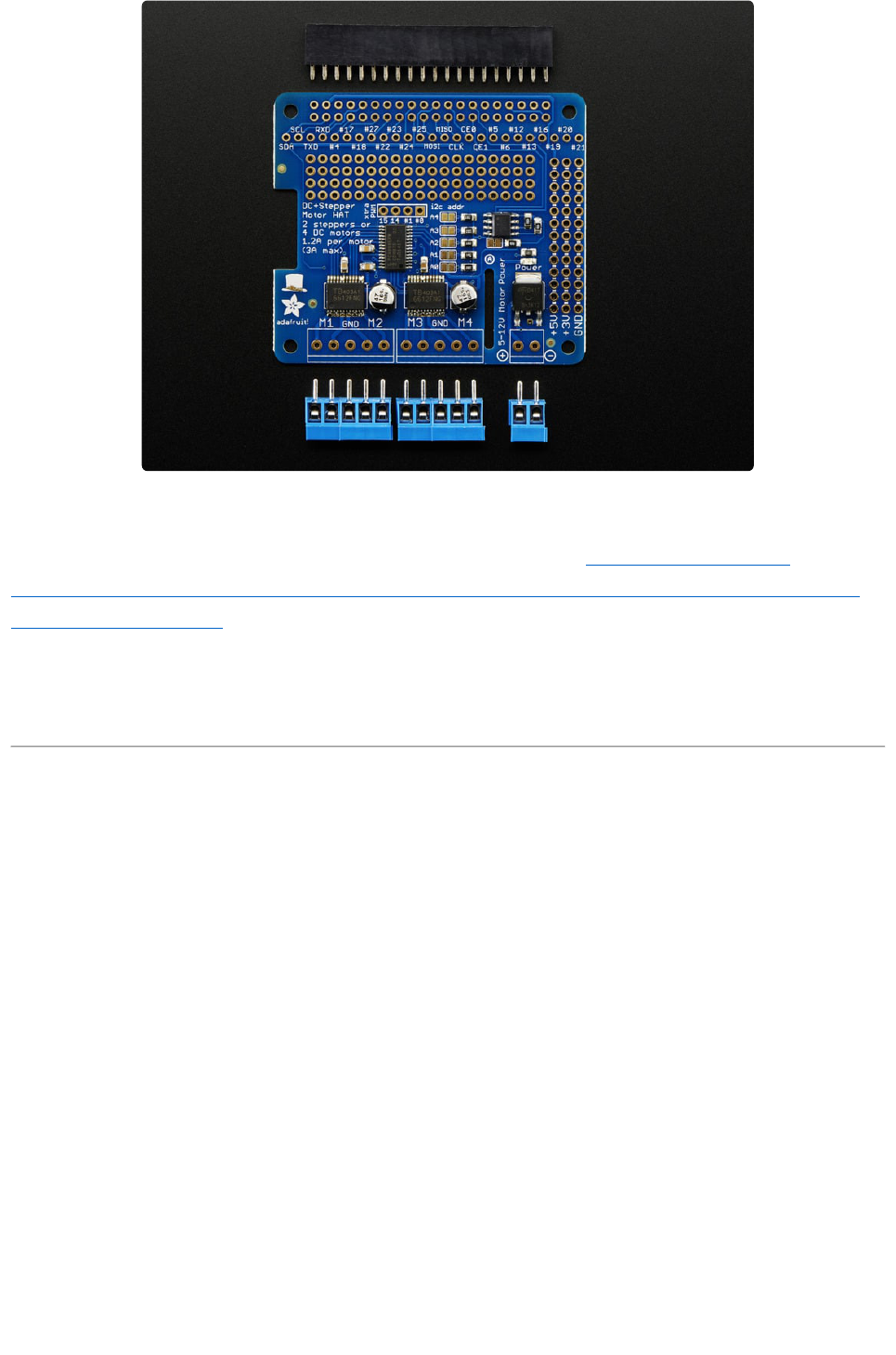
Overview
Let your robotic dreams come true with the new DC+Stepper Motor HAT from
Adafruit. This Raspberry Pi add-on is perfect for any motion project as it can drive up
to 4 DC or 2 Stepper motors with full PWM speed control.
Raspberry Pi and motors are not included
Since the Raspberry Pi does not have a lot of PWM pins, we use a fully-dedicated
PWM driver chip onboard to both control motor direction and speed. This chip
©Adafruit Industries Page 3 of 27

handles all the motor and speed controls over I2C. Only two GPIO pins (SDA & SCL)
are required to drive the multiple motors, and since it's I2C you can also connect any
other I2C devices or HATs to the same pins.
In fact, you can even stack multiple Motor HATs, up to 32 of them, for controlling up
to 64 stepper motors or 128 DC motors - just remember to purchase and solder in a
stacking header instead of the one we include.
Motors are controlled TB6612 MOSFET driver: with 1.2A per channel current
capability (20ms long bursts of 3A peak), a big improvement over L293D drivers and
there are built-in flyback diodes as well.
If connecting the Hat off-the Pi via jumpers, you will need to connect GND and
3.3v in addition to SDA and SCL.
©Adafruit Industries Page 4 of 27

We even had a little space so we added a polarity protection FET on the power pins
and a bit of prototyping area. And the HAT is assembled and tested here at Adafruit
so all you have to do is solder on the included 2x20 plain header and the terminal
blocks.
Lets check out these specs again:
4 H-Bridges: TB6612 chipset provides 1.2A per bridge (3A brief peak) with
thermal shutdown protection, internal kickback protection diodes. Can run
motors on 4.5VDC to 13.5VDC.
Up to 4 bi-directional DC motors with individual 8-bit speed selection (so, about
0.5% resolution)
Up to 2 stepper motors (unipolar or bipolar) with single coil, double coil,
interleaved or micro-stepping.
Big terminal block connectors to easily hook up wires (18-26AWG) and power
Polarity protected 2-pin terminal block and jumper to connect external 5-12VDC
power
Works best with Raspberry Pi model B+ and A+, but can be used with a model A
or B if you purchase a 2x13 extra-tall header and solder that instead of the
2x20(http://adafru.it/1658)
Install the easy-to-use Python library, check out the examples and you're ready
to go!
•
•
•
•
•
•
•
©Adafruit Industries Page 5 of 27
Comes with an assembled & tested HAT, terminal blocks, and 2x20 plain header.
Some soldering is required to assemble the headers on. Stacking header not
included, but we sell them in the shop so if you want to stack HATs, please pick one
up at the same time. (http://adafru.it/2223)
Raspberry Pi and motors are not included but we have lots of motors in the shop and
all our DC motors, and stepper motors work great.
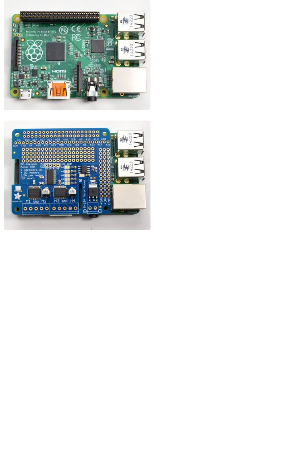
Assembly
Solder on Headers and Terminal Block
Before we can motorin' there's a little soldering to be done. This step will attach the
2x20 socket header so that we can plug this HAT into a Raspberry Pi, and the terminal
blocks so you can attach external power and motors.
©Adafruit Industries Page 6 of 27

And Solder!
Heat up your iron and solder in one
header connection on the right.
Once it is soldered, put down the solder
and reheat the solder point with your iron
while straightening the HAT so it isn't
leaning down
(For tips on soldering, be sure to check out
our Guide to Excellent Soldering(https://
adafru.it/aTk)).
Solder one point on the opposite side of
the connector
©Adafruit Industries Page 8 of 27


Check over your work so far, make sure
each solder point is shiny, and isn't
bridged or dull or cracked
Now grab the 3.5mm-spaced terminal
blocks. These will let you quickly connect
up your motor and power supply using
only a screw driver
You will have 3 x 2-pin terminal blocks and
2 x 3-pin terminal blocks
Slide each of the 3-pin terminal blocks into
a 2-pin to create two 5-pin blocks
Slide the terminal blocks along the edge of
the HAT, so that the 'mouth' of each block
is facing out.
You can use scotch or other plain tape to
keep the terminal blocks flat against the
PCB while you solder
©Adafruit Industries Page 11 of 27


Check over your work so far, make sure
each solder point is shiny, and isn't
bridged or dull or cracked
You're done! You can now move onto the
software side
Powering Motors
Motors need a lot of energy, especially cheap motors since they're less efficient.
Voltage requirements:
The first important thing to figure out what voltage the motor is going to use. If you're
lucky your motor came with some sort of specifications. Some small hobby motors are
only intended to run at 1.5V, but its just as common to have 6-12V motors. The motor
controllers on this HAT are designed to run from 5V to 12V.
MOST 1.5-3V MOTORS WILL NOT WORK or will be damaged by 5V power
Current requirements:
The second thing to figure out is how much current your motor will need. The motor
driver chips that come with the kit are designed to provide up to 1.2 A per motor, with
3A peak current. Note that once you head towards 2A you'll probably want to put a
heat-sink on the motor driver, otherwise you will get thermal failure, possibly burning
out the chip.
Honestly, for portable we recommend you use a big Lead Acid or multiple-AA NiMH
battery pack - use 4 to 8 batteries to vary the voltage from about 6V to 12V as your
motors require
You can't run motors off of a 9V battery so don't waste your time/batteries!
©Adafruit Industries Page 13 of 27

If you don't have to take your project on the go, a 9V 1A(http://adafru.it/63), 12V
1A(http://adafru.it/798), or 12V 5A w(http://adafru.it/352)ill work nicely
99% of 'weird motor problems' are due to having a voltage mismatch (too low a
voltage, too high a voltage) or not having a powerful enough supply! Even small DC
motors can draw up to 3 Amps when they stall.
©Adafruit Industries Page 14 of 27

Power it up
Wire up your battery pack to the Power terminal block on the right side of the HAT. It
is polarity protected but still its a good idea to check your wire polarity. Once the HAT
has the correct polarity, you'll see the green LED light up
Please note the HAT does not power the Raspberry Pi, and we strongly recommend
having two seperate power supplies - one for the Pi and one for the motors, as
motors can put a lot of noise onto a power supply and it could cause stability
problems!
Installing Software
We've written a handy CircuitPython library for the DC Motor and Stepper Pi Hat Kit
called Adafruit CircuitPython MotorKit(https://adafru.it/DdU) that handles all the
complicated setup for you. All you need to do is import the appropriate class from the
library, and then all the features of that class are available for use.
You can use this kit with a Raspberry Pi and Python thanks to Adafruit_Blinka, our
CircuitPython-for-Python compatibility library(https://adafru.it/BSN).
Enable I2C
The Adafruit DC and Stepper Motor Pi Hat kit uses I2C to communicate with your
Raspberry Pi. You will have to make I2C support work on your Pi before you begin.
Please visit our tutorial to enable I2C in the kernel!(https://adafru.it/dEO)
Python Installation of MotorKit Library
You'll need to install the Adafruit_Blinka library that provides the CircuitPython
support in Python. This will require enabling I2C on your Raspberry Pi and verifying
you are running Python 3. Since Linux changes often, please visit the CircuitPython on
Linux guide to get your computer ready(https://adafru.it/BSN)!
Once that's done, from your command line run the following command:
pip3 install adafruit-circuitpython-motorkit•
©Adafruit Industries Page 15 of 27

If your default Python is version 3 you may need to run pip instead. Just make sure
you aren't trying to use CircuitPython on Python 2.x, it isn't supported!
This will install the Adafruit CircuitPython MotorKit library along with the necessary
dependencies.
Using DC Motors
DC motors are used for all sort of robotic projects.
The Motor HAT can drive up to 4 DC motors bi-directionally. That means they can be
driven forwards and backwards. The speed can also be varied at 0.5% increments
using the high-quality built in PWM. This means the speed is very smooth and won't
vary!
Note that the H-bridge chip is not meant for driving continuous loads over 1.2A or
motors that peak over 3A, so this is for small motors. Check the datasheet for
information about the motor to verify its OK!
Connecting DC Motors
To connect a motor, simply solder two wires to the terminals on the motor (if they're
not already there!) and then connect them to either the M1, M2, M3, or M4 terminal
blocks on the Pi hat. If your motor is running 'backwards' from the way you expect,
swap the wires in the terminal block
©Adafruit Industries Page 16 of 27

For this demo, please connect it to M1.
Run python3 to get to the Python REPL.
Controlling DC Motors
To demonstrate the usage, we'll initialise the library and use Python code to control a
DC motor from the Python REPL.
First you'll need to import and initialize the MotorKit class.
from adafruit_motorkit import MotorKit
kit = MotorKit()
The four motor spots on the Pi hat are available as motor1 , motor2 , motor3 , and
motor4 .
In this example we'll use motor1 .
©Adafruit Industries Page 17 of 27

Now to move a motor you can set the throttle attribute. We don't call it speed
because it doesn't correlate to a particular number of revolutions per minute (RPM).
RPM depends on the motor and the voltage which is unknown.
For example to drive motor M1 forward at a full speed you set it to 1.0 :
kit.motor1.throttle = 1.0
To run the motor at half throttle forward use a decimal:
kit.motor1.throttle = 0.5
Or to reverse the direction use a negative throttle:
kit.motor1.throttle = -0.5
You can stop the motor with a throttle of 0 :
kit.motor1.throttle = 0
To let the motor coast and then spin freely set throttle to None .
kit.motor1.throttle = None
That's all there is to controlling DC motors with the Adafruit CircuitPython MotorKit
library! With DC motors you can build fun moving projects like robots or remote
controlled cars that glide around with ease.
Full Example Code
# SPDX-FileCopyrightText: 2021 ladyada for Adafruit Industries
# SPDX-License-Identifier: MIT
"""Simple test for using adafruit_motorkit with a DC motor"""
import time
import board
from adafruit_motorkit import MotorKit
kit = MotorKit(i2c=board.I2C())
kit.motor1.throttle = 1.0
time.sleep(0.5)
kit.motor1.throttle = 0
©Adafruit Industries Page 18 of 27

Using Stepper Motors
Stepper motors are great for (semi-)precise control, perfect for many robot and CNC
projects. This HAT supports up to 2 stepper motors. The python library works
identically for bi-polar and uni-polar motors.
Running a stepper is a little more intricate than running a DC motor but its still very
easy.
Connecting Stepper Motors
For unipolar motors: to connect up the stepper, first figure out which pins connected
to which coil, and which pins are the center taps. If its a 5-wire motor then there will
be 1 that is the center tap for both coils. Theres plenty of tutorials online on how to
reverse engineer the coils pinout.(https://adafru.it/aOO) The center taps should both
be connected together to the center GND terminal on the Motor HAT output block.
then coil 1 should connect to one motor port (say M1 or M3) and coil 2 should connect
to the other motor port (M2 or M4).
For bipolar motors: its just like unipolar motors except there's no 5th wire to connect
to ground. The code is exactly the same.
For this demo, please connect it to M1 and M2
Run python3 to get to the Python REPL.
©Adafruit Industries Page 19 of 27

Controlling Stepper Motors
To demonstrate the usage, we'll initialise the library and use Python code to control a
stepper motor from the Python REPL.
First you'll need to import and initialize the MotorKit class.
from adafruit_motorkit import MotorKit
kit = MotorKit()
Similar DC motors, stepper motors are available as stepper1 and stepper2 .
stepper1 is made up of the M1 and M2 terminals, and stepper2 is made up of the
M3 and M4 terminals.
We'll use stepper1 in our example.
The most basic function (and the default) is to do one single coil step.
kit.stepper1.onestep()
There are a number of optional features available for the onestep() function. Let's
take a look!
Stepping
Stepper motors differ from DC motors in that the controller (in this case, Raspberry Pi)
must tick each of the 4 coils in order to make the motor move. Each two 'ticks' is a
step. By alternating the coils, the stepper motor will spin all the way around. If the
coils are fired in the opposite order, it will spin the other way around.
If the python code or Pi crashes or stops responding, the motor will no longer move.
Compare this to a DC motor which has a constant voltage across a single coil for
movement.
©Adafruit Industries Page 20 of 27

"StepperMotor" by Wapcaplet; Teravolt.(https://adafru.it/enC)
There are four essential types of steps you can use with your Motor HAT. All four
kinds will work with any unipolar or bipolar stepper motor
Single Steps - this is the simplest type of stepping, and uses the least power. It
uses a single coil to 'hold' the motor in place, as seen in the animated GIF above
Double Steps - this is also fairly simple, except instead of a single coil, it has two
coils on at once. For example, instead of just coil #1 on, you would have coil #1
and #2 on at once. This uses more power (approx 2x) but is stronger than single
stepping (by maybe 25%)
Interleaved Steps - this is a mix of Single and Double stepping, where we use
single steps interleaved with double. It has a little more strength than single
stepping, and about 50% more power. What's nice about this style is that it
makes your motor appear to have 2x as many steps, for a smoother transition
between steps
Microstepping - this is where we use a mix of single stepping with PWM to
slowly transition between steps. It's slower than single stepping but has much
higher precision. We recommend 8 microstepping which multiplies the # of
steps your stepper motor has by 8.
You can call the onestep function with two optional keyword arguments. To use
these, you'll need to import stepper as well.
1.
2.
3.
4.
©Adafruit Industries Page 21 of 27

from adafruit_motor import stepper
Then you have access to the following options:
direction , which should be one of the following constant values:
stepper.FORWARD (default)
stepper.BACKWARD
style , which should be one of the values:
stepper.SINGLE (default) for a full step rotation to a position where one
single coil is powered
stepper.DOUBLE for a full step rotation to position where two coils are
powered providing more torque
stepper.INTERLEAVE for a half step rotation interleaving single and
double coil positions and torque
stepper.MICROSTEP for a microstep rotation to a position where two
coils are partially active
release() which releases all the coils so the motor can free spin, and also
won't use any power
The function returns the current step 'position' in microsteps which can be handy to
understand how far the stepper has moved, or you can ignore the result.
To takea double-coil step backward call:
kit.stepper1.onestep(direction=stepper.BACKWARD, style=stepper.DOUBLE)
You can even use a loop to continuously call onestep and move the stepper, for
example a loop of 200 microsteps forward for smooth movement:
for i in range(200):
kit.stepper1.onestep(style=stepper.MICROSTEP)
That's all there is to controlling a stepper motor from CircuitPython! Steppers are
handy motors for when you need smooth or precise control of something--for
example 3D printers and CNC machines use steppers to precisely move tools around
surfaces.
•
◦
◦
•
◦
◦
◦
◦
•
©Adafruit Industries Page 22 of 27

Full Example Code
# SPDX-FileCopyrightText: 2021 ladyada for Adafruit Industries
# SPDX-License-Identifier: MIT
"""Simple test for using adafruit_motorkit with a stepper motor"""
import time
import board
from adafruit_motorkit import MotorKit
kit = MotorKit(i2c=board.I2C())
for i in range(100):
kit.stepper1.onestep()
time.sleep(0.01)
See the library API documentation here(https://adafru.it/19HD).
Python Docs
Python Docs(https://adafru.it/DeE)
Stacking HATs
One of the cool things about this HAT design is that it is possible to stack them. Every
HAT you stack can control another 2 steppers or 4 DC motors (or a mix of the two)
You can stack up to 32 HAT for a total of 64 steppers or 128 DC motors! Most people
©Adafruit Industries Page 23 of 27

will probably just stack two or maybe three but hey, you never know. (PS if you drive
64 steppers from one Raspberry Pi send us a photo, OK?)
If you need to control a bunch of servos as well, you can use our 16-channel servo
HAT and stack it with this HAT to add a crazy large # of servos.(http://adafru.it/2327)
Stacking HATs is very easy.Each HAT you want to stack on top of must have stacking
headers installed.(http://adafru.it/2223) The top HAT does not have to have stacking
headers unless you eventually want to put something on top of it.
The only thing to watch for when stacking HATs is every HAT must have a unique I2C
address. The default address is 0x60. You can adjust the address of the motor HATs
to range from 0x60 to 0x80 for a total of 32 unique addresses.
Addressing the HATs
Each board in the stack must be assigned a unique address. This is done with the
address jumpers on the left side of the board. The I2C base address for each board is
0x60. The binary address that you program with the address jumpers is added to the
base I2C address.
To program the address offset, use a drop of solder to bridge the corresponding
address jumper for each binary '1' in the address.
The bottom-most jumper is address bit #0, then the one above of that is address bit
#1, etc up to address bit #5
©Adafruit Industries Page 24 of 27

Board 0: Address = 0x60 Offset = binary 0000 (no jumpers required)
Board 1: Address = 0x61 Offset = binary 0001 (bridge A0)
Board 2: Address = 0x62 Offset = binary 0010 (bridge A1, the one above A0)
Board 3: Address = 0x63 Offset = binary 0011 (bridge A0 & A1, two bottom jumpers)
Board 4: Address = 0x64 Offset = binary 0100 (bridge A2, middle jumper)
etc.
Stacking in Code
Now that you've changed the I2C address on the hardware, you need to set it in your
code. When you initialise the class, you can set the address.
from adafruit_motorkit import MotorKit
# Initialise the first hat on the default address
kit1 = MotorKit()
# Initialise the second hat on a different address
kit2 = MotorKit(address=0x61)
Then you can use kit1 and kit2 to control the motors attached to the associated
hat.
Downloads
Motor ideas and tutorials
Wikipedia has tons of information(https://adafru.it/aOF) on steppers
Jones on stepper motor types(https://adafru.it/19oe)
Jason on reverse engineering the stepper wire pinouts(https://adafru.it/aOI)
Files
PCA9685 PWM driver(https://adafru.it/emJ)
TB6612 Motor driver(https://adafru.it/emK)
PCB files on GitHub(https://adafru.it/rEN)
HAT Fritzing object in the Adafruit Fritzing Library(https://adafru.it/aP3)
Note that address 0x70 is the "all call" address for the controller chip on the HAT.
All boards will respond to address 0x70 - regardless of the address jumper
settings.
•
•
•
•
•
•
•
©Adafruit Industries Page 25 of 27


Bonnet!
©Adafruit Industries Page 27 of 27
