
i
i
-
-
V
V
u
u
P
P
r
r
o
o
v
v
7
7
.
.
0
0
H
H
e
e
l
l
p
p
CARRIER CORPORATION ©2020 · Catalog No. 11-808-677-01 · 4/25/2020

Verify that you have the most current version of this document from www.hvacpartners.com or
www.accounts.ivusystems.com or your local Carrier office.
Important changes are listed in Document revision history at the end of this document.
CARRIER CORPORATION © 2020. All rights reserved throughout the world. i-Vu is a registered trademark of Carrier
Corporation. All other trademarks are the property of their respective owners.
The contents of this guide and the associated Carrier software are property of Carrier Corporation and its respective
licensors, and are protected by copyright. For more information on the software and licensing, see the About section in
the software's Help menu.
The content of this guide is furnished for informational use only and is subject to change without notice. Carrier
Corporation assumes no responsibility or liability for any errors or inaccuracies that may appear in the informational
content contained in this guide. This document contains no technical data controlled by the EAR or ITAR.

Contents
What is an i-Vu® Pro system? .................................................................................................................................... 1
A typical i-Vu® Pro system .................................................................................................................................. 1
i-Vu® Pro tools ...................................................................................................................................................... 2
What's new in v7.0 ...................................................................................................................................................... 1
What's new in the i-Vu® Pro application .......................................................................................................... 1
What's new in the ViewBuilder application ...................................................................................................... 3
What's new in the SiteBuilder application ........................................................................................................ 5
What's new in the Snap application .................................................................................................................. 5
Running i-Vu® Pro Server ........................................................................................................................................... 6
To start the i-Vu® Pro system ............................................................................................................................. 6
To send a message to logged in operators ....................................................................................................... 6
To log off an operator ........................................................................................................................................... 7
To shut down a system ........................................................................................................................................ 7
Getting to know the interface ..................................................................................................................................... 8
Navigation trees .................................................................................................................................................... 9
Navigating the system ...................................................................................................................................... 10
To show, hide, or resize the navigation tree .................................................................................................. 11
Zooming in and out ........................................................................................................................................... 12
Using right-click menus ..................................................................................................................................... 13
To print the action pane .................................................................................................................................... 14
Colors and status in the i-Vu® Pro interface ................................................................................................. 14
Colors and setpoints .......................................................................................................................................... 15
Working with equipment in the interface ................................................................................................................ 16
Graphics pages................................................................................................................................................... 18
To attach a graphic in the i-Vu® Pro interface .................................................................................. 19
To edit a graphic from the i-Vu® Pro application in ViewBuilder ...................................................... 20
To edit a graphic on an i-Vu® Pro client ............................................................................................ 20
To organize multiple graphics for a tree item .................................................................................... 21
To control equipment using an interactive zone sensor ................................................................... 22
Properties pages ................................................................................................................................................ 23
To view or edit properties on a Properties page ................................................................................ 24
Point types ........................................................................................................................................... 25
Logic pages ......................................................................................................................................................... 26
To view a Logic page ........................................................................................................................... 26
To locate a microblock, section, or label ........................................................................................... 27
To change properties, alarms, or trends ............................................................................................ 27
Using a Logic page to troubleshoot .................................................................................................... 27
Changing multiple microblock properties ..................................................................................................... 28
To use Global Modify ........................................................................................................................... 29
To use Global Copy .............................................................................................................................. 31
Checking controller status................................................................................................................................ 32
Status messages ................................................................................................................................. 32
Handling parameter mismatches ....................................................................................................... 36
Managing setpoints ........................................................................................................................................... 37
Adjust setpoints ................................................................................................................................... 39
Demand Control .................................................................................................................................. 40
Configuring Optimal Start ................................................................................................................................. 41
Optimal Start ....................................................................................................................................... 41
Optimal Start Type ............................................................................................................................... 42
Schedules ................................................................................................................................................................... 45
Creating and modifying schedules.................................................................................................................. 46
Contents
To view schedules ............................................................................................................................... 46
To print schedules ............................................................................................................................... 46
To apply a schedule to equipment ..................................................................................................... 47
To apply a schedule to a group of items ............................................................................................ 48
To edit or delete a schedule ............................................................................................................... 49
Effective schedules ............................................................................................................................. 50
Using schedule categories ................................................................................................................................ 51
Creating a custom schedule category ................................................................................................ 51
To add a custom schedule category in the i-Vu® Pro interface ....................................................... 52
To view, edit, or delete a schedule category ...................................................................................... 53
i-Vu® Pro CCN schedules .................................................................................................................................. 53
Trends ......................................................................................................................................................................... 55
To collect trend data for a point ...................................................................................................................... 56
Viewing a built-in, single-point trend graph ................................................................................................... 58
Creating a custom trend graph ........................................................................................................................ 58
To create a custom trend graph ......................................................................................................... 59
To edit a custom trend graph ............................................................................................................. 59
Adding trend categories ................................................................................................................................... 60
Using trend graphs ............................................................................................................................................ 61
To view trend data in a spreadsheet program ................................................................................... 62
Alarms ........................................................................................................................................................................ 63
Viewing, acknowledging, and deleting alarms .............................................................................................. 64
To view alarms in the i-Vu® Pro interface.......................................................................................... 64
To control which alarms you see ........................................................................................................ 66
To acknowledge alarms ...................................................................................................................... 67
To delete alarms .................................................................................................................................. 68
To receive audible notification of alarms ........................................................................................... 69
Setting up alarm actions .................................................................................................................................. 69
To assign alarm actions to alarm sources ......................................................................................... 70
Alarm Popup ........................................................................................................................................ 71
Print ...................................................................................................................................................... 74
Run External Program ......................................................................................................................... 75
Send Alphanumeric Page.................................................................................................................... 76
Send E-mail .......................................................................................................................................... 78
Send SNMP Trap ................................................................................................................................. 81
Send Web Service Request ................................................................................................................ 82
Write Property ...................................................................................................................................... 84
Write to Database ............................................................................................................................... 84
Write to File .......................................................................................................................................... 87
Setting up an alarm source in the i-Vu® Pro interface ................................................................................ 89
To set up, edit, or disable alarm sources ........................................................................................... 89
To simulate an alarm .......................................................................................................................... 91
To view all instances of an alarm source ........................................................................................... 91
Alarm categories ................................................................................................................................. 92
Edit alarm messages........................................................................................................................... 92
Using field codes ................................................................................................................................................ 93
Formatting field codes ........................................................................................................................ 93
Field Codes .......................................................................................................................................... 94
Reports ....................................................................................................................................................................... 98
Preconfigured reports ....................................................................................................................................... 98
To run a preconfigured report ......................................................................................................... 100
Custom reports ................................................................................................................................................. 102
Creating a custom report ................................................................................................................. 103
To run a custom report .................................................................................................................... 122
To edit or delete a custom report .................................................................................................... 123

To export or import a custom report ............................................................................................... 123
To organize custom reports by category ......................................................................................... 124
Using a custom report as the source for a Graphics page ............................................................ 125
Troubleshooting custom reports ..................................................................................................... 139
To create a PDF, XLS, or CSV file ................................................................................................................... 140
Scheduling reports ........................................................................................................................................... 140
To schedule a report ........................................................................................................................ 141
To manage scheduled reports ......................................................................................................... 142
Working with legacy (v6.5 and earlier) custom reports ............................................................................. 143
To create an Equipment Summary report....................................................................................... 143
To create an Equipment Values report ........................................................................................... 144
To create a Trend Samples report ................................................................................................... 146
To save a v6.5 or earlier custom report's design ........................................................................... 147
To edit or delete a v6.5 or earlier custom report ........................................................................... 148
Operator access ...................................................................................................................................................... 149
Privilege sets .................................................................................................................................................... 149
Privileges ........................................................................................................................................... 150
To add or edit a privilege set ........................................................................................................... 153
To delete a privilege set ................................................................................................................... 153
Operators and operator groups ..................................................................................................................... 153
To add or edit an operator ............................................................................................................... 154
To delete an operator ....................................................................................................................... 155
To add or edit an operator group .................................................................................................... 155
To delete an operator group ............................................................................................................ 156
To change My Settings .................................................................................................................................... 156
Advanced security ............................................................................................................................................ 157
Location-dependent operator access ............................................................................................. 157
Recording reasons for edits (21 CFR Part 11) ............................................................................... 161
Advanced password policy ............................................................................................................... 162
Manual commands................................................................................................................................................. 163
Using DEBUG MODE................................................................................................................................................ 169
Running the i-Vu® Pro autopilot ........................................................................................................................... 170
To set up the i-Vu® Pro autopilot .................................................................................................................. 170
To run the i-Vu® Pro autopilot ....................................................................................................................... 171
To run autopilot with Windows Vista ............................................................................................................ 171
System database maintenance ............................................................................................................................ 172
To back up a system ....................................................................................................................................... 172
To compact and defragment ......................................................................................................................... 172
To minimize the database size ...................................................................................................................... 173
To safely shut down the i-Vu® Pro application for database server maintenance ............................... 174
Defining i-Vu® Pro paths........................................................................................................................................ 175
Absolute path ................................................................................................................................................... 175
Relative path .................................................................................................................................................... 176
Determining a path or microblock property ................................................................................................ 177
To set up a BACnet/IP connection in the i-Vu® Pro interface ............................................................................ 179
To set up a BACnet/IP Service Port connection in the i-Vu® Pro interface using an i-Vu® XT or TruVu™ device
................................................................................................................................................................................. 181
Testing the server-to-client connections ............................................................................................................... 182
To ping the server from each client .............................................................................................................. 182
To test the HTTP connection .......................................................................................................................... 182
Testing the server-to-controller connections ........................................................................................................ 183
To ping a controller on the IP network from the i-Vu® Pro server ........................................................... 183
Setting up BACnet Broadcast Management Devices (BBMDs) ........................................................................... 184
Contents
To set up BBMDs in SiteBuilder ..................................................................................................................... 185
To set up BBMDs through the i-Vu® Pro interface ..................................................................................... 185
To set up BBMDs using the BBMD Configuration Tool............................................................................... 186
To set up the i-Vu® Pro server as a foreign device ..................................................................................... 188
Using a Modstat to troubleshoot your system ...................................................................................................... 190
To obtain a Modstat ........................................................................................................................................ 190
Modstat field descriptions .............................................................................................................................. 191
Communicating locally with Open devices ........................................................................................................... 195
To connect to a device's Local Access port ................................................................................................. 195
Troubleshooting a Local Access connection ............................................................................................... 196
To set up a Local Access connection ............................................................................................................ 197
Communicating locally with i-Vu® XT or TruVu™ devices ................................................................................... 199
To communicate with the i-Vu® XT or TruVu™ device's Service Port ...................................................... 199
To communicate locally through the i-Vu® XT or TruVu™ device's Rnet port ........................................ 200
To set up a BACnet/Rnet connection in the i-Vu® Pro interface ............................................................. 201
Troubleshooting an Rnet connection ............................................................................................................ 202
Network security ..................................................................................................................................................... 204
What is TLS (HTTPS)? ...................................................................................................................................... 204
To set up TLS using a Certificate Authority (CA) certificate ............................................................ 205
To set up TLS using a self-signed certificate .................................................................................. 210
Setting up i-Vu® Open or i-Vu® XT or TruVu™ devices in the i-Vu® Pro application......................................... 214
Find and upload routers and controllers ...................................................................................................... 214
Verify network and device settings ............................................................................................................... 215
Working with control programs for programmable controllers .......................................................................... 217
Reload, create, or edit a control program in EquipmentBuilder or Snap ............................................... 217
Add or delete a custom control program and graphic ............................................................................... 219
To edit a control program on an i-Vu® Pro client ....................................................................................... 221
Setting up a CCN devices in the i-Vu® Pro application ....................................................................................... 222
To find and download devices in a single CCN Gateway system ............................................................. 223
To set up a system for multiple CCN Gateways .......................................................................................... 224
To find and download i-Vu® CCN routers in a multiple CCN Gateway system ...................................... 225
To set up the Carrier® ChillerVu in a multiple CCN Gateway system ...................................................... 227
To assign and download a custom CCN equipment file ............................................................................ 229
To view an equipment's CCN tables ............................................................................................................. 231
Working with Universal and Comfort Controllers (CCN) ...................................................................................... 232
Create custom equipment files in EquipmentBuilder for UC/CC's that link only to CNN points......... 232
Create custom equipment files for UC/CC's that link to TPI points......................................................... 234
Create stand-alone applications.................................................................................................................... 236
Map to Point procedures for the UC/CC ....................................................................................................... 236
Working with Terminal System Managers ........................................................................................................... 237
Create custom equipment files in EquipmentBuilder for Terminal System Managers (TSM) ............. 237
Assign and download a TSM equipment file in the i-Vu® Pro application ............................................. 238
Configure the path to the source of the point for TSM Groups and Zones ............................................. 241
Integrating third-party data into the i-Vu® Pro v7.0 system ............................................................................... 242
To discover third-party BACnet networks, devices, and objects ............................................................... 242
To determine the number of non-BACnet third-party points used in a system...................................... 244
To determine the number of third-party points used in a controller ....................................................... 244
To configure LonWorks points using the LonWorks Integration Tool ...................................................... 245
Create navigation tree for the User view .............................................................................................................. 246
Configuring your system ........................................................................................................................................ 247
Work with controllers, set up Linkage, and perform Test and Balance .................................................. 247
Commissioning equipment ............................................................................................................................ 247

Step 1: Check out point setup ........................................................................................................ 247
Step 2: Check controller communication....................................................................................... 253
Step 3: Check equipment operation .............................................................................................. 253
Step 4: Check the commissioned status ....................................................................................... 253
Optional: Import/export calibration data ........................................................................................ 254
Adjust airflow configuration for VAV or VVT controllers .................................................................. 254
Commissioning equipment using Field Assistant ...................................................................................... 255
Providing source files to Field Assistant ......................................................................................... 255
To download source files from the i-Vu® Pro application .............................................................. 256
To export source files from the i-Vu® Pro application ................................................................... 256
To upload source files to the i-Vu® Pro application ....................................................................... 256
To import source files in the i-Vu® Pro application ........................................................................ 256
Downloading to controllers ............................................................................................................................ 257
Download Options ............................................................................................................................ 258
To download from the Downloads page ......................................................................................... 258
To download from a Properties page .............................................................................................. 259
If a controller fails to download ....................................................................................................... 259
Monitoring and controlling equipment ................................................................................................................. 260
To lock a BACnet point or value .................................................................................................................... 260
To force a CCN point value ............................................................................................................................. 261
To set up peer caching .................................................................................................................................... 262
Working with drivers in the i-Vu® Pro interface ................................................................................................... 263
To change or upgrade a driver ....................................................................................................................... 263
Working with touchscreen or BACview® files in the i-Vu® Pro interface .......................................................... 264
To select a different screen file ..................................................................................................................... 264
To edit a screen file on an i-Vu® Pro client ................................................................................................. 265
Setting up i-Vu® Pro client devices and web browsers ....................................................................................... 266
Setting up and using a computer with the i-Vu® Pro system ................................................................... 267
Setting up and using a web browser to view the i-Vu® Pro interface ..................................................... 267
To set up and use Internet Explorer ................................................................................................ 267
To set up and use Microsoft Edge ................................................................................................... 268
To set up and use Mozilla Firefox .................................................................................................... 269
To set up and use Google Chrome .................................................................................................. 270
To set up and use Safari .................................................................................................................. 271
Using System Options ............................................................................................................................................ 273
My Settings ....................................................................................................................................................... 273
System Settings ............................................................................................................................................... 274
General tab ....................................................................................................................................... 274
Security tab ....................................................................................................................................... 279
Communications tab ........................................................................................................................ 280
Scheduled Tasks tab ........................................................................................................................ 281
Daylight Saving tab .......................................................................................................................... 282
Add-ons tab ....................................................................................................................................... 283
To register and download your i-Vu® Pro license ....................................................................................... 285
Update ............................................................................................................................................................... 286
Update the SAL library ..................................................................................................................... 286
Adding links or text to i-Vu® Pro's login page ...................................................................................................... 289
To add links to the login page........................................................................................................................ 290
To add text to the login page ......................................................................................................................... 290
Editing a system remotely ..................................................................................................................................... 291
To import a clipping ......................................................................................................................................... 291
Managing files on a remote i-Vu® Pro server ............................................................................................. 292
Options for running the i-Vu® Pro system ............................................................................................................ 293
Contents
Running i-Vu Pro Server without connecting to controllers ....................................................................... 293
Switching i-Vu Pro Server to a different system .......................................................................................... 293
Running i-Vu Pro Server as a Windows® service ........................................................................................ 293
To install i-Vu® Pro Server service .................................................................................................. 294
To start i-Vu® Pro Server as a Windows service ............................................................................ 294
To set up the service for network printing ...................................................................................... 295
To stop or uninstall i-Vu® Pro Server service ................................................................................. 295
To determine if i-Vu® Pro Server service is installed ..................................................................... 296
Setting up a system for non-English languages ................................................................................................... 297
Preparing your workstation for non-English text......................................................................................... 297
Installing a language pack ............................................................................................................................. 299
Creating control programs and translation files for a non-English system ............................................ 299
To enter a key term in the Snap application ................................................................................... 299
Translation files ................................................................................................................................ 300
To create and implement a translation file..................................................................................... 300
Creating graphics for a non-English system ................................................................................................ 302
Setting the language font ................................................................................................................ 302
To create a Non-English graphic ...................................................................................................... 302
Creating a non-English system in SiteBuilder ............................................................................................. 304
To choose the language(s) for your system .................................................................................... 304
To create your system ...................................................................................................................... 304
System language .............................................................................................................................. 305
To set an operator’s language in the i-Vu® Pro interface ......................................................................... 305
Editing translation files or control programs for a non-English system .................................................. 305
To edit a bundled resource .............................................................................................................. 305
Copying translation files to another system ................................................................................... 306
Integrating i-Vu® Pro data into other applications .................................................................................... 306
Document revision history ..................................................................................................................................... 307

i-Vu Pro v7.0 Help CARRIER CORPORATION ©2020
All rights reserved
1
An i-Vu® Pro system is a web-based building automation system that can be accessed from anywhere in the world
through a web browser, without the need for special software on the workstation. Through the web browser, you
can perform building management functions such as:
adjust setpoints and other control parameters
set and change schedules
graphically trend important building conditions
view and acknowledge alarms
run preconfigured and custom reports on energy usage, occupant overrides, and much more
A typical i-Vu® Pro system
An i-Vu® Pro system uses a network of microprocessor-based controllers to control heating and air conditioning. A
web-based server communicates with these controllers and generates the i-Vu® Pro interface that the user can
access through a web browser. Through the interface, you can gather information, change operating properties,
run reports, and perform other building management functions on a single building or an entire campus.
The i-Vu® Pro client uses a supported web browser to access i-Vu® Pro Server as a website.
i-Vu® Pro supports:
Unlimited simultaneous users
Multiple operating systems and databases
CCN, Open, and third-party devices
Built-in alarming, trending, and reporting
Third-party integration
Secure server access using TLS
What is an i-Vu® Pro system?

What is an i-Vu® Pro system?
i-Vu Pro v7.0 Help CARRIER CORPORATION ©2020
All rights reserved
2
i-Vu® Pro tools
Develop and configure graphics and a system database for your i-Vu® Pro system using the following i-Vu® Pro
tools.
NOTE The i-Vu® Pro v7.0 Tech Tools and Customer Tools USB drives have a built-in license that expires 2 years
after the software is released. When prompted during installation, browse to the i-Vu® Pro v7.0 non-expiring
license that you obtained from Carrier.
Use...
To...
ViewBuilder
Create or edit graphics
SiteBuilder
Create and modify the system database
Build a system for multiple CCN Gateways
Tech tools for the Installer only:
Use...
To...
EquipmentBuilder
Build or edit control programs (.equipment files) for programmable
controllers. Can also produce graphics, sequence of operation, and
screen files
Alarm Notification
Receive a message on any networked computer that is running the i-
Vu® Pro Alarm Notification Client application
Virtual BACview®
View and change property values and the controller's real time clock
BBMD Configuration Tool
Configure BACnet/IP Broadcast Management Devices (BBMDs)
NOTE If your system has multiple routers that reside on different IP
subnets, you must set up one router on each IP subnet as a BACnet/IP
Broadcast Management Device (BBMD).
MSTP Capture Utility
Capture BACnet traffic on MS/TP. It is intended for situations where
Carrier Control Systems Support needs a network capture to
troubleshoot communications.
Test & Balance
Calibrate airflow in a VAV or VVT Zone controller
Calibrate the static pressure in a VVT Bypass controller
Commission air terminals
Override reheat and terminal fans
NOTE Use Test & Balance to manipulate the controllers associated with
an air source, but not the air source itself, or heating and cooling
equipment, such as chillers and boilers.
Snap
Build custom control programs using individual blocks of programming
code called microblocks
LonWorks Integration Tool
Generate the microblock addresses automatically for third-party
LonWorks points
AppLoader
Use to download .clipping files to restore factory defaults and check
Module Status (Modstat) through the Rnet port
Field Assistant
Service or start up and commission a piece of equipment or a network of
controllers.

i-Vu Pro v7.0 Help CARRIER CORPORATION ©2020
All rights reserved
1
What's new in the i-Vu® Pro application
Feature
Improvement
v7.0 cumulative update #7
To set up a Local Access
connection (page 197), To set
up a BACnet/Rnet connectiion
in the i-Vu® Pro interface
(page 197)
System Options > System Settings > Connections
BACnet Local Access has been changed to BACnet/Rnet Connection
To set up a BACnet/IP Service
Port Connection in the i-Vu®
Pro interface (page 181)
i-Vu® XT or TruVu™ only
You can now use a BACnet/IP Service Port Connection
TruVu™ controllers added to i-Vu® XT references
v7.0 cumulative update #6
Advanced security
Location-dependent operator access
Configurable password policies
Operator comments and verification required before system can accept
changes
All trend data is recorded during a Daylight Saving Time change
Custom reports
You can reference a data value in a table (page 129) allowing you to incorporate
the data in a report
v7.0 cumulative update #3
New fields in System Settings
(page 274)
The General tab now shows the System Language and lets you choose the
number of levels to show in i-Vu® Pro paths.
v7.0
What's new in v7.0

i-Vu Pro v7.0 Help CARRIER CORPORATION ©2020
All rights reserved
2
Feature
Improvement
Custom reports (page 102)
Custom reports are now created and managed through the new Report
Manager.
You can export one or more custom reports to a file so that they can be
imported into another system.
A custom report can provide data for the following new items on a Graphics
page:
Data table (page 125)
Chart (page 130)
Color map (page 134)
See What's new n the ViewBuilder application (page 3) for more information on
the above items.
NOTE To support upgraded systems, you can still create and access legacy
(v6.5 and earlier) custom reports (page 143).
Scheduled Reports (page 140)
You can set up a report to run on a recurring basis. The report is saved as a file
(PDF, CSV, or XLS), and you can choose to have it automatically emailed to
someone.
Default Email Server
Configuration (page 274)
The Email Server Configuration settings, used by scheduled reports and the
Send Email alarm action, are now located on the System Settings > General
tab.
Send Email alarm action (page
78)
This alarm action can use the default Email Server Configuration settings
defined in System Settings, or you can enter settings specific to the alarm
action.
New FDD alarm categories
(page 92)
The i-Vu® Pro application now has two new alarm categories, FDD Comfort and
FDD Energy.
Send Web Service Request
alarm action (page 82)
This new alarm action sends a web service request to a third-party server when
an alarm occurs.
Disabling the Schedules
feature (page 274)
You can disable the Schedules (page 45) feature in System Settings > General
tab so that Schedules are no longer visible in the i-Vu® Pro interface.
Improved Foreign Device
Registration (page 188)
If your system requires that i-Vu® Pro be registered as a foreign device to a
BBMD, you can now define a second BBMD in case the first one fails.
If your system requires that i-Vu® Pro be registered as a foreign device to a
BBMD, you can now define a second BBMD in case the first one fails.
System Statistics (page 274)
The System Statistics button on the General tab of System Settings now
includes the following totals:
Number of controllers
Number of controllers that can run control programs
Number of points, regardless of vendor
Re-authentication of operator
for 21 CFR Part 11
If an operator is required to record a reason for making system changes, the
operator is now required to re-enter their system password in the box where
they record the changes.
Run External Program alarm
action (page 75)
This alarm action can now be set up only when running i-Vu® Pro Design
Server.
Add-ons (page 283)
By default, i-Vu® Pro now allows only signed add-ons that are supported by
Carrier. This default can be overridden in SiteBuilder. See What's new in the
SiteBuilder application.

i-Vu Pro v7.0 Help CARRIER CORPORATION ©2020
All rights reserved
3
Feature
Improvement
Security enhancements
The i-Vu® Pro login page no longer shows customer identifying "Licensed
To" and "For use at" information, but the customer information is still
available in the About box.
Apache Tomcat web server has been upgraded to v7.0.82.
The i-Vu® Pro application has been upgraded to Java 8 update 144.
64-bit server
i-Vu® Pro v7.0 will run only on a server with a 64-bit operating system. If you
have a previous i-Vu® Pro version that is running on a 32-bit server, you will
need to upgrade your server before installing v7.0.
WAP device support
This has been removed from the i-Vu® Pro application. Smart phone support
introduced in v6.5 replaced this functionality.
What's new in the ViewBuilder application
Feature
Improvement
v7.0 cumulative patch #6
Data table
You can reference a data value in a table (page 129) allowing you to incorporate
the data in a report
v7.0 cumulative patch #5
Associations
The new Associations window lets you:
Add color ovals more efficiently to a floorplan or campus map.
Tie the color ovals on a floorplan or campus map to an i-Vu® Pro custom
report.
Custom Equipment Touch
screens
Custom-sized Equipment Touch screens can be created to display on mobile
devices, such as a cellphone of tablet.
v7.0

i-Vu Pro v7.0 Help CARRIER CORPORATION ©2020
All rights reserved
4
Feature
Improvement
Data tables (page 125)
and charts (page 130)
These new controls on a Graphics page pull data from an i-Vu® Pro report. The
chart control allows you to specify a line chart, pie chart, horizontal bar chart, or
vertical bar chart.
Data table Vertical bar chart
Color maps (page 134)
A Graphics page color map shows specified colors for various conditions that are
defined in an i-Vu® Pro report.
Default graphic size
The default graphic size in ViewBuilder is now 1666 x 849 pixels.
Local Variables
ViewBuilder now preserves local variables through cut/copy and paste, as well as
when importing a .viewsymbol.
Layers
ViewBuilder now preserves layers when importing a .viewsymbol.
If cutting/copying a selection assigned to layers, you must hold Shift while
pasting in a new file to preserve layer assignments.

i-Vu Pro v7.0 Help CARRIER CORPORATION ©2020
All rights reserved
5
Feature
Improvement
Dowloading a Custom
Equipment Touch file
If a .touch file contains many screens or large images that cause the file to become
too large for the controller's memory, you can download only the name of the
.touch file to the controller instead of the entire file. You will then need to manually
copy the .touch file to your device.
What's new in the SiteBuilder application
Feature
Improvement
v7.0 cumulative patch #3
HTTP redirect to HTTPS
If you enable web server ports for Both HTTP and HTTPS, you can optionally elect
to have HTTP requests automatically redirected to HTTPS.
Improved security settings
To increase security, the i-Vu® Pro application defaults to the following settings:
If your system is set to use TLS, the i-Vu® Pro application automatically uses
TLS 1.2.
The i-Vu® Pro application requires SOAP applications to run over HTTPS.
The i-Vu® Pro application allows only add-ons that have been approved by
Carrier.
NOTE If needed, you can override these defaults in SiteBuilder; however, doing
so will lessen the security of your system.
What's new in the Snap application
Feature
Improvement
Support for the following new optional features has been added to Snap. When released, you can download
them from https://accounts.ivusystems.com/tsaplctrackweb.nsf/download under Technician Tools Software
and Updates > v7.0 installs and updates or
http://hvacpartners.com/Pages/PS/Software/ControlsDownloads/aspx under i-Vu SAL Files and Updates.
Improved Edit Order
Provides more flexibility and reduces the time needed to create property pages
for equipment.
Translation Assistance Tool
Simplifies the process of creating non-English control programs.
i-Vu Pro v7.0 Help CARRIER CORPORATION ©2020
All rights reserved
6
The i-Vu Pro Server application communicates with the system's controllers and accesses and maintains the
system database. You view and edit the system in client web browsers. i-Vu Pro Server must be running for an
operator to log in from a web browser.
The application's Current Users, Connections, and Output tabs let you monitor the status of the system. Output
information is continually archived to i-Vu_Pro_x.x\logs\< date >\core.txt.
To start the i-Vu® Pro system
1 Click Start > All Programs > i-Vu_Pro_ x.x > i-Vu Pro Server.
TIP If you run the i-Vu Pro Server application as a Windows® service, your computer can automatically
start the application every time the computer starts. See Running i-Vu Pro Server as a Windows service (page
293).
2 Open a web browser on one or more client computers.
3 Verify that your web browser is set up to display the i-Vu® Pro interface. See Setting up i-Vu® Pro client
devices and web browsers (page 266).
4 Type the i-Vu® Pro server's address in the web browser's address field.
NOTE You can type http://localhost if i-Vu Pro Server and the web browser are running on the same
computer.
5 Enter a Name and Password.
To send a message to logged in operators
Messages are delivered immediately to i-Vu® Pro client web browsers. You can send multiple messages, but the
operator must click Ok for the first message before the next message can be delivered. If the web browser window
is minimized, the message is not visible.
1 On the i-Vu Pro Server application's Current Users tab, click beside the user you want to send a message
to. Or, click Notify All Users.
2 Type a message.
3 Click OK.
Running i-Vu® Pro Server

i-Vu Pro v7.0 Help CARRIER CORPORATION ©2020
All rights reserved
7
To log off an operator
From the i-Vu Pro Server application
NOTE The operator will be logged off without warning.
1 On the i-Vu Pro Server Current Users tab, right-click the operator, then select Log Off User.
2 Click Yes.
From the i-Vu® Pro interface
NOTE The operator will be logged off without warning.
1 In the i-Vu® Pro interface, press Ctrl+M.
2 Type whoson in the manual command field.
3 Obtain the ID number of the operator you want to log off.
4 Press Ctrl+M.
5 Type logoffuser x (where x is the ID number).
6 Click OK.
To shut down a system
1 In the i-Vu Pro Server application, select Server > Shut Down.
2 Optional: Select a delay option, then edit the Notification message.
3 Click Shut Down.

i-Vu Pro v7.0 Help CARRIER CORPORATION ©2020
All rights reserved
8
Computer and large-screen mobile interface
Small-screen mobile interface
Most of the i-Vu® Pro interface is the same on small-screen mobile devices except for the differences shown
below.
Getting to know the interface

i-Vu Pro v7.0 Help CARRIER CORPORATION ©2020
All rights reserved
9
When you click to hide the tree, the button changes to .
Help and Print are in the menu.
NOTES
After you log in, you will see the page defined as your starting location on the My Settings page. To change
your opening page, see To change My Settings (page 273).
Roles/privileges control what an operator can see or do in the i-Vu® Pro system. If you cannot see or do
something that you read about in Help, ask your System Administrator to check your role/privileges.
Use only the i-Vu® Pro interface to navigate; do not use the web browser’s navigation buttons.
Click on any tab to refresh the page.
Navigation trees
User tree
This tree lets you navigate through the i-Vu® Pro interface using the system's geographic layout. You set this up on
the Installer tab under Arrange User View.
Installer Tree
This tree lets users with the appropriate privileges navigate through the i-Vu® Pro interface using the system's
network layout.
Schedule Groups tree
On this tree, you can create groups that can consist of areas, equipment, or other groups. You can then assign a
schedule to the entire group instead of the individual items. See To apply a schedule to a group of items (page 48).
System Options tree
Click > System Options (page 273) for the setup and maintenance of your system.
My Settings
Lets you change settings that are specific to you such as your password, viewing
preferences and contact information. See To change My Settings (page 273).
System Settings
Contains the system-wide settings that control the way the i-Vu® Pro system runs.
See System Settings (page 274).
Operators
Privilege Sets
Operator Groups
Lets your system administrator define operators and what they can see and do in
the i-Vu® Pro interface. See Operator access (page 149).

i-Vu Pro v7.0 Help CARRIER CORPORATION ©2020
All rights reserved
10
Categories
Lets you define categories for schedules (page 51), alarms (page 92), graphics
(page 21), properties, trends (page 60), and reports (page 124). Categories allow
you to view or control groups of similar items.
Scheduled Reports
Shows any report that was scheduled on the report's page. See To manage
scheduled reports for details.
Connections
Lets you set up, start/stop, and troubleshoot your network connections.
Services
Shows internal processes of the i-Vu® Pro application for troubleshooting.
License Administration
Lets you update your i-Vu® Pro license.
Update
Click Update to select and apply patch, service packs, drivers, language packs,
graphics libraries, and Help updates.
Client Installs
Lets you install applications that are to run on client computers.
Navigating the system
To navigate in the i-Vu® Pro interface:
1 Select the item you want in the navigation tree.
2 Select the action buttons and their drop-down menus.
3 Use the tabs to filter the information further.
4 Click links on Graphics and Properties pages to jump to related pages and open microblock popups.
NOTE Use only the i-Vu® Pro interface to navigate; do not use the browser’s navigation buttons.
5 Click on any tab to refresh the page.

i-Vu Pro v7.0 Help CARRIER CORPORATION ©2020
All rights reserved
11
To show, hide, or resize the navigation tree
On a computer or large screen mobile device
Click at the top of the navigation tree to hide or show the tree.
Click and drag the tab on the right side of the tree to adjust its width.
In the Installer view, click and drag the tab at the top of Arrange User View to adjust the height of the window.
On a small-screen mobile device
Touch at the top of the navigation tree to hide the tree. Touch to show it.
Double-tap the arrow on the right side of the tree to widen the tree. Double-tap again to return to the original size.

i-Vu Pro v7.0 Help CARRIER CORPORATION ©2020
All rights reserved
12
Zooming in and out
On a computer
To zoom in and out on the i-Vu® Pro interface:
○ Hold down Ctrl and press + or -. Press Ctrl+0 to return to 100%.
○ Hold down Ctrl while rolling your mouse wheel.
○ Use your web browser's zoom functions.
If a graphic does not fit in the action pane, right-click it and select Scale to Fit to make it fit the action pane.
Select Scale to Fit again to return the graphic to its original size.
On a mobile device
Apple® iPad and iPhone
Double-tap to zoom in/out.
Microsoft® Surface
TM
Pinch-zoom works on individual frames, instead of the whole screen. So, you can zoom and scroll the
navigation pane and action pane separately.
If browser text is too small, use Ctrl + to increase Internet Explorer's zoom level, then reload the page.
Google
TM
Nexus
TM
and Nexus Lumia
Pinch-zoom to zoom in/out.

i-Vu Pro v7.0 Help CARRIER CORPORATION ©2020
All rights reserved
13
Using right-click menus
On a computer
You can right-click the following items to select options:
A tree item
The action pane
A property
A trend
On a mobile device
To access the right-click menu for:
A tree item–Select the item first, then touch and hold the item for several seconds.
The action pane–Touch and hold the item for several seconds.
i-Vu Pro v7.0 Help CARRIER CORPORATION ©2020
All rights reserved
14
To print the action pane
On a computer
Click at the top of the page to print the contents of the action pane. Set the print orientation to Landscape in
the Print dialog box.
TIP To print a Graphics page that exceeds the size of the action pane, right-click the graphic and select Scale
to Fit.
On a mobile device
Touch and then select Print.
Colors and status in the i-Vu® Pro interface
The following colors indicate equipment status the i-Vu® Pro interface. These colors are visible on graphic pages
and in the setpoint graphs.
Color
Color Name
Status Code
Condition Indicated
Mustard
none
In equipment when running i-Vu Pro Design Server
Purple
0 or 15
In a controller—non-operational or no communications
In equipment—a hardware or software error
Charcoal
14
In a controller—a download is required or is already in
progress
In equipment—a controller has stopped
Coral
13
Control program error
Red
2 or 9
Heating or cooling alarm
Orange
8
Maximum cooling
Dark blue
3
Maximum heating
Yellow
7
Moderate cooling
Light blue
4
Moderate heating
Gray
1
Unoccupied/inactive
White
10
Occupied/active

i-Vu Pro v7.0 Help CARRIER CORPORATION ©2020
All rights reserved
15
Color
Color Name
Status Code
Condition Indicated
Light green
6
Free cooling
Green
5
In a controller—operational or operational read only
In equipment—No heating or cooling
Colors and setpoints
Thermographic colors indicate how much a zone’s actual temperature differs from its setpoints.
Five conditions may affect a zone’s thermographic color:
Setpoint adjust
Timed local override (TLO)
Optimal start
Demand level
Hysteresis
In the examples below, a zone’s heating occupied setpoint is 70° and its cooling occupied setpoint is 74°.
If you
normally
see...
when the zone
temp is...
but...
then you will
see...
green
72.5°
someone adjusts the setpoints (for example, with a setpoint
adjust of two degrees, the new setpoints would be 68 and
72°)
yellow
gray
73°
(unoccupied)
someone presses the Override button on a zone sensor to
use the occupied setpoints
green
gray
77°
(unoccupied)
the zone is in optimal start and is ramping up to its
occupied setpoint in the few hours before occupancy
an occupied
color
yellow
75°
the zone’s electric meter is in demand level 2 with relaxed
setpoints of 68 and 76°
green
green
73.5°
cooling began when the temperature rose above 74° and
the temperature has not yet dropped beyond the 1°
hysteresis (to 73°)
yellow

i-Vu Pro v7.0 Help CARRIER CORPORATION ©2020
All rights reserved
16
You can view and adjust equipment operation from the following pages:
Devices pages
Select the system level on the navigation tree to
view the Devices page, where you can:
Upload source files or just parameters
Download source files, schedules, parameters,
or BBMD tables
Check status and error messages
View model, IP address, drivers, device ID
Edit device names
Graphics pages (page 18)
You can view and adjust your essential building
controls on most Graphics pages.
Equipment drawings show the current status of
mechanical equipment.
Adjust setpoints (page 37) on a Graphics page.
To upload a graphic from ViewBuilder, double-click
the controller in the navigation tree or right-click and
select Configure.
Working with equipment in the interface

i-Vu Pro v7.0 Help CARRIER CORPORATION ©2020
All rights reserved
17
Logic pages (page 26)
Logic pages show the control program for a piece of
equipment. Use the sequence of control and yellow
status values on the Logic pages for troubleshooting
your mechanical equipment.
Properties pages (page 23)
You can monitor and control point sources.
1 Select the equipment in the navigation tree.
2 Click Properties page > Control Program tab.
3 Expand the plus sign next to the desired table.
Properties/Microblock popups
Click a property or point to open the microblock
popup to view and change details, including forcing
or locking values.

i-Vu Pro v7.0 Help CARRIER CORPORATION ©2020
All rights reserved
18
Graphics pages
You can view and adjust your system from Graphics pages, which include navigation maps, floor plans, and
equipment.
Some typical items that may appear on a graphics page are:
Button or switch to turn equipment on or off
Input field to set a property value
Drop-down list to select a state
Interactive zone sensor to override an unoccupied schedule
Setpoint graph to adjust setpoints (page 37)
Trend graph to view trend (page 55) information
Link to jump to another i-Vu® Pro page or to the Internet
A data table, chart, or color map that pulls information from a custom report (page 125).
NOTES
Right-click a value, then select Details to view and change properties in the microblock pop-up.
Right-click a value, then select Global Modify (page 29) to view and change the property in other control
programs.
A yellow dashed box around a value indicates the value is locked or forced.
If a graphic does not fit in the action pane, right-click it and select Scale to Fit to make it fit the action pane.
Select Scale to Fit again to return the graphic to its original size.
When a chart that is based on a report is displayed on a Graphics page, you can hover over various points on
the chart to see values. You can also click on each item in the legend to turn that information on and off. See
Using a custom report as the source for a Graphics page (page 125) for more information on a chart.

i-Vu Pro v7.0 Help CARRIER CORPORATION ©2020
All rights reserved
19
To attach a graphic in the i-Vu® Pro interface
1 On the navigation tree, right-click the item that you want to attach a graphic to, then select Configure.
2 Equipment graphic only: If the system has other control programs of this type, select which control programs
you want to change.
NOTES
○ If the control program is in an IP router, the second option will change the graphic for all control programs
of this type only on the IP network.
○ If the control program is on the network below an IP router, the second option will not change the graphic
for the router's control programs of this type.
3 Do one of the following:
If the graphic is...
In the Views Available list
a. Select the graphic, then click Attach.
b. Click Accept.
Not in the Views Available list
a. Click Add New.
b. Browse to select the view file.
c. Click Open.
d. Click Continue.
e. Click Close.
f. Click Close again.
NOTES
Select a graphic in the Attached list to edit the following information for the graphic:
Display Name–The name that appears in the Graphics button drop-down list
Category–The name of the category that multiple graphics may be sorted into in the Graphics button
drop-down list
NOTE Changes to Display Name or Category apply only in the i-Vu® Pro interface and are not retained if
you export source files (page 256).
Reference Name–The name that is used to create links to the graphic in ViewBuilder
Default View–Sets the selected graphic as the default view if the tree item has multiple graphics. The
default graphic is bolded in the Attached list.
Included in download–Equipment graphics only. Select to have the .view file included in an All Content
download so that it can be uploaded by Field Assistant. The graphic will have beside it in the Attached
list. Requires 4.x or later drivers.
You can click Delete Unused at the bottom of the Views section to delete all unattached graphic files from
your system.
i-Vu Pro v7.0 Help CARRIER CORPORATION ©2020
All rights reserved
20
To edit a graphic from the i-Vu® Pro application in ViewBuilder
1 In the i-Vu® Pro interface, double-click the controller in the navigation tree or right-click and select Configure.
2 Click Edit Existing button under Views.
3 Click Save as and place the file in an appropriate folder.
4 Open ViewBuilder.
5 Select File > Open. Browse to your saved graphic and click to open.
6 Edit and save with a new name - the original system name is locked and cannot be used for an edited graphic.
NOTE Names are case sensitive and should not have spaces and/or special characters.
To edit a graphic on an i-Vu® Pro client
On an i-Vu® Pro client, you can get a copy of a graphic from the server, edit it, then put it back on the server.
To get the graphic
1 On the i-Vu® Pro navigation tree, right-click the item that the graphic is attached to, then select Configure.
2 At the bottom of the Views section, click Edit Existing.
3 Select the graphic you want to edit.
4 Click Save.
5 Browse to the folder you want to put the file in.
6 Click Save.
7 Click Close.
8 Click Close again.
To put the edited graphic back on the server
1 On the i-Vu® Pro navigation tree, right-click the item that the graphic is attached to, then select Configure.
2 At the bottom of the Views section, click Add New.
3 Browse to select the .view file.
4 Click Open.
5 Click Continue.
6 Click Close.
7 Click Close again.

i-Vu Pro v7.0 Help CARRIER CORPORATION ©2020
All rights reserved
21
To organize multiple graphics for a tree item
In the i-Vu® Pro interface, you can create categories and assign graphics to them so that the Graphics button drop-
down menu has the graphics arranged by category. This is typically done in ViewBuilder or SiteBuilder. See "To
define i-Vu® Pro navigation" in ViewBuilder Help and "To attach graphic files" in SiteBuilder Help.
To add a Graphics category in the i-Vu® Pro interface
1 On the System Options tree, click to the left of the Categories folder, then select Graphic.
2 Click Add.
3 Type the Category Name and Reference Name.
4 Optional: Select a privilege so that only operators with that privilege can access graphics in the category.
5 Click Accept.
NOTES
To edit a category, select the category, make your changes, then click Accept.
To delete a category, select the category, click Delete, then click Accept.
To assign a graphic to a category in the i-Vu® Pro interface
1 On the navigation tree, right-click the item that the graphic is attached to, then select Configure.
2 Under Views, select the graphic in the Attached list.
3 Select the category in the Category field.
4 Click Accept.

i-Vu Pro v7.0 Help CARRIER CORPORATION ©2020
All rights reserved
22
To control equipment using an interactive zone sensor
An equipment graphic may include an interactive zone sensor that provides you with the following control.
If the sensor is a...
You can...
ZS
Click to raise the setpoint or to lower the setpoint.
Click to override the schedule and put the zone in an occupied state.
To cancel an override, continue clicking until the display shows 0.
See that the zone is in an occupied state when the green LED is lit.
SPT Standard, Plus, or Pro
Click the WARMER or COOLER button to adjust the setpoint.
Click the MANUAL button to override the schedule and put the zone in an
occupied state.
Click the INFO button to cycle through the following information:
Outside air temperature, if enabled in the control program
Override time remaining
Heating setpoint
Cooling setpoint
See the Occupied/Unoccupied state in the display.
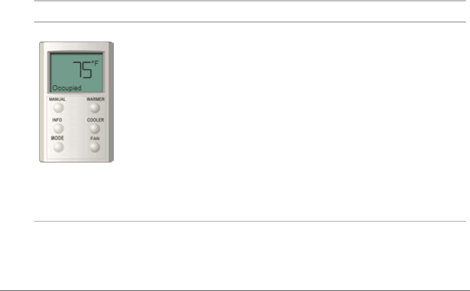
i-Vu Pro v7.0 Help CARRIER CORPORATION ©2020
All rights reserved
23
If the sensor is a...
You can...
SPT Pro Plus
Click the WARMER or COOLER button to adjust the setpoint.
Click the MANUAL button to override the schedule and put the zone in an
occupied state.
Click the INFO button to cycle through information such as:
Outside air temperature
Override time remaining
Heating setpoint
Cooling setpoint
Click the FAN button to adjust the fan speed.
Click the MODE button to perform customer-specific functions.
See the Occupied/Unoccupied state in the display.
Properties pages
Properties pages are automatically generated from control programs. Properties pages show the status of a piece
of equipment and the points/properties currently stored in it. See Check out point setup (page 247) for details.
Use Properties pages to:
View the status of a piece of equipment. See Colors and status in the i-Vu® Pro interface (page 14).
View or change the equipment point/properties currently stored in the controller.
Commission equipment (page 247)
Set up Linkage.
Refer to your individual controller's Installation and Start-up Guide for detailed explanations of the
points/properties.

i-Vu Pro v7.0 Help CARRIER CORPORATION ©2020
All rights reserved
24
To view or edit properties on a Properties page
1 Select a controller on the navigation tree, click Properties, and then select the appropriate tab.
NOTE You must resolve any condition described in red text at the top of the page before a Properties page
can obtain current information from its controller.
2 Click to show property details.
3 Do one of the following to change a property:
○ Select or clear a checkbox
○ Select an item on a drop-down list
○ Change text in a text field
4 Click Accept.
NOTES
Click the bold, underlined point name to open the editable microblock pop-up
Right-click a value, then select Details to view and change properties in the microblock pop-up.
Right-click a value, then select Global Modify (page 29) to view and change the property in other control
programs.
Use Search/Replace on the Network Points tab to replace a term in the point address with another address.
For the legend of status colors, see Colors and status in the i-Vu® Pro interface (page 14).
A yellow dashed box around a value indicates the value is locked or forced.

i-Vu Pro v7.0 Help CARRIER CORPORATION ©2020
All rights reserved
25
Point types
A point name on the Properties page is followed by a code that tells you the point type. The table below describes
each code.
Code
Point type
AI
Analog Input
ANI
Analog Network Input
ANI2
Analog Network Input 2
ANO
Analog Network Output
ANO2
Analog Network Output 2
AO
Analog Output
ASVI
BACnet Analog Sensed Value Input
AV
Analog Value
BAI
BACnet Analog Input
BALM
BACnet Alarm
BAO
BACnet Analog Output
BAV
BACnet Analog Value
BBI
BACnet Binary Input
BBO
BACnet Binary Output
BBV
BACnet Binary Value
BFM
Floating Motor
BI
Binary Input
BMSV
BACnet Multi-State Value
BNI
Binary Network Input
BNI2
Binary Network Input 2
BNO
Binary Network Output
BNO2
Binary Network Output 2
BO
Binary Output

i-Vu Pro v7.0 Help CARRIER CORPORATION ©2020
All rights reserved
26
Code
Point type
BPTA
Pulse to Analog Input
BPWM
Pulse-Width Output
BRS
RS Sensor
BRSF
RS Sensor Fan
BSVI
BACnet Binary Sensed Value Input
BTLO
Timed Local Override
BTRN
Trend Log
BV
Binary Value
DI
Digital Input
DO
Digital Output
EVT
BACnet Alarm
POLLAVG
Average Analog Properties
POLLMAX
Maximum Analog Properties
POLLMIN
Minimum Analog Properties
POLLTOT
Total Analog Properties
PTA
Pulse to Analog Input
TLO
Timed Local Override
Logic pages
The Logic page shows a custom control program for a programmable controller. The live data (yellow text) is
updated every few seconds and when you click the Logic button. The control program uses exact property values
for its calculations, but values are rounded to 2 decimal places when displayed on the Logic page.
TIP Click anywhere on the Logic page, then use your keyboard's Page Up, Page Down, and arrow keys to scroll
through the page.
NOTE If you find an unexpected value on a Properties page or a Logic page, you can use the Logic page to
troubleshoot.
To view a Logic page
1 Select a custom control program on the navigation tree.
2 Click Logic.
3 Click a microblock to view its details.

i-Vu Pro v7.0 Help CARRIER CORPORATION ©2020
All rights reserved
27
To locate a microblock, section, or label
1 Right-click the Logic page, then select Jump To.
2 Do one of the following:
○ On the Microblock or Section tab, select an item to have it located and highlighted.
○ On the Label tab, select a label to display a reduced logic page outlined in yellow that shows all instances
of the label. A red box indicates an output label; a yellow box indicates an input label. Click a red or yellow
box to jump to that label in the full-size logic page.
NOTE You can also click a label on the full-size Logic page to display the reduced Logic page.
To change properties, alarms, or trends
1 Click a microblock on the equipment’s Logic page.
2 In the microblock pop-up, click the Properties, Alarms, or Trends button.
3 Change properties, alarms, or trends for that microblock in the same way that you would make changes on a
regular Properties (page 23), Alarms (page 89), or Trends (page 56) page.
4 Click Accept.
NOTE Right-click a value, then select Global Modify (page 29) to view and change the property in other control
programs.
Using a Logic page to troubleshoot
The i-Vu® Pro application monitors your system and provides feedback. If you get unexpected feedback, you can
use a Logic page as a troubleshooting tool. On the Logic page, work your way backward (right to left) through the
sequence in the control program to discover what caused the problem. See Microblock Reference to understand
what each microblock in the sequence is doing.
Unexpected feedback
Possible cause
Space temperature reads
excessively high or low
The sensor has a short (or open) circuit. Verify wires are properly
connected at the sensor and controller.
A sensor is missing or configured incorrectly. Open the sensor or input
microblock from the Logic page to verify its configuration.

i-Vu Pro v7.0 Help CARRIER CORPORATION ©2020
All rights reserved
28
Unexpected feedback
Possible cause
Equipment displays an unexpected
color - effective setpoints are
different than the programmed
setpoints
NOTE Equipment operates using effective setpoints. Open the Setpoint
microblock from the Logic page and check the following:
Hysteresis
Demand Level
Optimal Start
Timed Local Override (TLO)
Setpoint Adjust
Gaps in trend data on trend graph
Usually gaps result if network communication was disrupted or a point was
temporarily disabled.
If the gap is not the result of interrupted communication, send reports
more frequently. From the Logic page, open the trend microblock that
displayed the gap in data, then decrease the notification threshold so that
it is approximately 40% of the buffer size (allocated memory size) for that
microblock.
The i-Vu® Pro application is not
receiving alarms from a BACnet
alarm microblock
Locate the microblock on the Logic page. If the color square on the
microblock is black, the alarm is disabled. To enable it:
1 Click the microblock.
2 In the microblock pop-up, click the Alarms button.
3 On the Enable/Disable tab, select Potential alarm source.
The equipment is on when I expect
it to be off, or off when I expect it to
be on
Use the Logic page to determine whether the program is sending an
unexpected signal and why, or if the problem is with the physical
equipment. For example, the On-Off-Auto (OOA) switch on the controller for
that equipment may be locked in the On (Hand) position.
Sensor value on the Properties
page does not match the reading
from handheld sensor
Calibrate the sensor.
On the Logic page, check to see if the output point is locked on.
Changing multiple microblock properties
Two i-Vu® Pro features, Global Modify and Global Copy, allow you to view and change multiple microblock
properties at the same time.
CAUTION Global Modify and Global Copy are convenient for making widespread changes in your system. But,
because they do not take into account the operation of individual equipment, your changes could produce
undesired results in your equipment or system operation. Use with caution because these features do not have an
Undo function.
TIP Click to copy a microblock's reference path to the clipboard so you can paste it into another field or
application.
i-Vu Pro v7.0 Help CARRIER CORPORATION ©2020
All rights reserved
29
To use Global Modify
Use the Global Modify feature to:
View a microblock’s full path, control program name, and the privileges required to change its properties.
View or change a single property in several control programs at one time.
View errors on Graphics and Properties pages.
1 Browse to any page that displays the property you want to view or change.
2 Do one of the following to open Global Modify:
○ Alt+click the property.
○ Right-click the property and select Global Modify.
3 Make changes to the Control Program field, if needed.
NOTES
○ Use wildcards in the Control Program field to broaden the search.
For example:
vav* matches vav, vav1, vavx, vav12345
vav*z matches vavz, vav1z, vavxz, vav12345z
vav*1*2 matches vav12, vavabc1xyz2
vav?? matches vav11, vav12, vavzz, but does not match vav, vav1, vav123
* matches any control program
○ Click Show Advanced to view the location, value, and privileges associated with this property.

i-Vu Pro v7.0 Help CARRIER CORPORATION ©2020
All rights reserved
30
4 Select the tree item that you want to search under for every occurrence of that microblock in other control
programs.
5 Click Find All.
6 Select the properties in the list that you want to change.
7 Do one of the following:
a) Type a New Value to the right of each selected item.
b) Select Enable All, type a new value in b, then click Set All To.

i-Vu Pro v7.0 Help CARRIER CORPORATION ©2020
All rights reserved
31
c) Select Enable All, type a new value in c, then click Change All By.
8 Click Apply Changes.
NOTE To modify several properties in multiple control programs at the same time, use Global Copy.
To use Global Copy
Use Global Copy to copy any or all of the following from one control program to other equipment using the same
control program:
Embedded trend graph settings
Custom trend graphs
Custom reports
Other editable properties to other pieces of equipment using the same control program.
1 On the navigation tree, right-click the piece of equipment that has the properties you want to copy, then select
Copy Control Program Properties.
2 Click OK when you see This will copy this control programs properties to other control programs of the same
type. Continue?. This opens the next screen and does not lock in any changes.
3 In the Global Copy dialog box, select the items that you want to copy.
4 Select the area on the tree containing similar control programs that you may want to copy these properties to,
then click Search.
All instances at that level and below are listed in the expanded lower window.
5 Check or uncheck items as needed.

i-Vu Pro v7.0 Help CARRIER CORPORATION ©2020
All rights reserved
32
6 Do one of the following:
○ Check Skip bad values to copy all values except a bad value (it cannot be copied because you do not
have the necessary privilege, the property to be copied is undefined, etc.).
○ Uncheck this field to prevent any values from being copied if a bad value is found.
7 Click Apply Changes, then close the Global Copy dialog box.
Checking controller status
On the i-Vu® Pro navigation tree, you can select a router or the system level and then click the Devices button to:
View the status of controllers (page 32)
View controller information such as address, model, driver, and .view files included in download
Download or upload to resolve a mismatch (page 36)
Troubleshoot network communication
Download or upload files for Field Assistant (page 255)
NOTES
Use Ctrl+click, Shift+click, or the Select All checkbox to select multiple controllers.
Click Hold to stop pending downloads or uploads. Active downloads or uploads cannot be stopped.
Icons in the Tasks column indicate the following:
Active—The i-Vu® Pro application is downloading to the controller.
Active—The i-Vu® Pro application is uploading from the controller.
Pending—You initiated the download, and the controller is waiting for its turn to download.
Failed—The download failed. See If a controller fails to download (page 259).
On Hold—Indicates you clicked Hold to stop a pending download.
Click in the upper left-hand corner to view a log of activity on the Devices page in the current session. Copy
to Clipboard lets you copy the text to paste it into another application.
Status messages
On the i-Vu® Pro navigation tree, you can select a router or the system level and select the Devices page to view
the status of controllers. The Status column shows a description of the controller's current state. Hold your cursor
over that description to see hover text with a more detailed description.
If multiple conditions exist, the i-Vu® Pro interface displays the message with the highest priority.

i-Vu Pro v7.0 Help CARRIER CORPORATION ©2020
All rights reserved
33
The table below shows all possible messages. The message color indicates the following:
Black—In process
Red—An error occurred
Blue—Requires action from the user
i-Vu® Open routers/controllers
Status column message
Hover text message
Notes
Black messages:
Downloading
The controller is downloading,
communications may be disabled
Uploading
The controller is uploading,
communications may be disabled
Pending
This controller is waiting to be processed.
Processing Clipping
Clipping operation in progress. Do not
make changes during this operation, as
they may corrupt your system.
Red messages:
Communications Error
Cannot communicate with this controller.
Connection Disabled
The connection for this controller has been
disabled.
Occurs if someone stopped the
connection.
Connection Error
The connection for this controller failed to
start.
Occurs if the connection is misconstrues
or failed to start.
Controller offline
The controller is offline.
This only appears for equipment
controlling slave devices that it is
unable to communicate with.
Download Failed
(Message depends on the cause of the
failure.)
Download Not Permitted
This controller is not permitted to
download.
Error
An unknown error has occurred.
Missing Files
Upload failed. Server is missing the source
files.
Not Uploadable
This controller is not configured for
content upload.
Occurs if you attempt to upload a
controller with a pre-4.x driver.
Out of Service
This controller is out of service.
Unsupported Controller
This controller does not support content
upload.

i-Vu Pro v7.0 Help CARRIER CORPORATION ©2020
All rights reserved
34
Status column message
Hover text message
Notes
Upload Not Permitted
This controller is not permitted to upload.
USB Unplugged
Cannot communicate with the controller
because the USB cable is unplugged.
Applies only to the i-Vu® Standard and
Plus applications.
Blue messages:
Controller Replaced
This controller has been replaced by
another controller of the same type in the
field.
4.x driver only
Download All Content
Please download all content to the
controller.
Download Parameters
To download parameters, highlight row
and select Parameters from the Download
Action menu and click Download.
Download Schedule
To download schedules, highlight row and
select Schedules from the Download
Action menu and click Download.
Driver Parameter
Mismatch
Driver parameter differences detected.
Upload parameters from the controller or
download parameters to the controller.
Network Ready for
Upload
To upload this network, select the router in
the tree and Find Devices.
Parameter Mismatch
Control program parameter differences
detected. Upload parameters from the
controller or download parameters to the
controller.
Program Mismatch
Content differences detected. Upload all
content from the controller or download all
content to the controller.
4.x driver only
Unprogrammed
Controller
Applies only to a programmable controller
that does not have any control programs in
it.
To add control programs, click Add
Control Program.
Upload All Content
Please upload all content from the
controller.
General messages:
This controller is ok.
Cancelled
The last operation on this controller was
cancelled

i-Vu Pro v7.0 Help CARRIER CORPORATION ©2020
All rights reserved
35
CCN controllers/equipment
Status column message
Hover text message
Notes
<blank>
This is a known control program from a
previous discovery, but communications
with it has not been attempted since the
user logged in.
Successful rescan.
Downloading
Downloading changes. Communications
will resume shortly.
New Control Program
A new controller was found at the scanned
address and added to the system.
New Version Applied
This controller's program or views have
been updated with a newer version.
Red messages:
Communications Error
Cannot communicate with this controller.
Download Failed
<The message is specific to the failure.>
USB Unplugged
Cannot communicate with the controller
because the USB cable is unplugged.
Applies only to the i-Vu® Standard and
Plus applications.
Blue messages
Classification Mismatch
The controller at this address was
previously a Bridge routing to other
controllers.
Download All Content
Please download all content to the
controller.
Model Mismatch
The controller at this address is the wrong
model.
Rescan Required
A configuration change was made to this
control program therefore a rescan is
required to get the correct graphic and
control logic components.

i-Vu Pro v7.0 Help CARRIER CORPORATION ©2020
All rights reserved
36
Handling parameter mismatches
A parameter mismatch occurs when a value in a controller does not match the value in the system database. This
can be a driver or control program value.
Use either of the following methods to handle mismatches in your system.
Method 1: Check Always resolve parameters on mismatch on the System Settings > Communications tab to
have the i-Vu® Pro application automatically upload if a value was changed in the controller or automatically
download if a value was changed in the i-Vu® Pro interface.
Method 2: Uncheck Always resolve parameters on mismatch so that you can evaluate a mismatch to
determine the correct value.
To find mismatches in your system
If your system uses Method 2, you can find mismatches in the following places:
○ The Devices page > Manage tab > Status column will show Parameter Mismatch.
○ The Properties page for a controller, driver, control program, or point will show one of the following red
messages at the top of the page stating:
Control Program parameter differences detected.
Driver parameter differences detected.
Parameter download required.
The value that has a discrepancy will appear with a purple box around it. Hover your cursor over the field
to see:
or
○ Go to Reports > Equipment > Parameter Mismatch, and then click Run to get a report of any existing
mismatches in your system.
NOTE The Downloads page > Tasks column will show Resolve Parameters for any mismatches that your
system discovered in the 3 places listed above.

i-Vu Pro v7.0 Help CARRIER CORPORATION ©2020
All rights reserved
37
To resolve a mismatch
1 Go to one of the following:
Devices page - Click the Parameter Mismatch link
Properties page that shows one of the red messages above
2 Click one of the following:
○ Resolve to let the i-Vu® Pro application download changes made in the i-Vu® Pro interface or upload
changes made in the controller. Click the Details button to see what the discrepancy is and whether
Resolve will download or upload parameters. See NOTE below.
○ Upload to upload the parameters from the controller to the i-Vu® Pro application
○ Download to download the parameters from the i-Vu® Pro application to the controller
NOTE On the Devices page with Show Control Programs unchecked, if a controller has simultaneous
mismatches in the driver and control program, clicking Details will show that a control program mismatch
exists but it will only show details for the driver mismatch. You must go to the control program in the tree to
see details of that mismatch. However, clicking Resolve will resolve both mismatches.
Managing setpoints
The Setpoint graphic shown on a standard equipment graphic indicates the base setpoint values (Occupied
High/Low, Unoccupied High/Low). The i-Vu® Pro application reads these values back periodically, typically within
10 seconds. The timing can vary based on network traffic, the number of controllers in the database, and several
other variables. Setpoints that are changed in the field via another user interface are displayed in the i-Vu® Pro
interface as soon as they are detected.
You can, at any time, change the setpoints from i-Vu® Pro graphics by using the slider or by entering numeric
values directly. Updated setpoints are transmitted to the controller when you Accept the changes. Setpoints can
also be changed on the Properties page > Control Program tab > Space Temperature and Setpoints. or
Configuration > Setpoints.
NOTE Power and Standard operators may only edit Occupied/Unoccupied and Heating/Cooling setpoints. They
cannot edit Demand levels or more detailed setpoint parameters.
The various color bars indicate adherence to or deviation from the setpoint. You can change the current default
settings for setpoint deviation. Select a color band on the setpoint graph to see the current setpoints in the
Heating and Cooling fields. The values in this graphic are Fahrenheit. See setpoint descriptions below.

i-Vu Pro v7.0 Help CARRIER CORPORATION ©2020
All rights reserved
38
NOTE This graphic is an example only. Your setpoints may differ.
Color
Condition
Green
Temperature is within the Occupied Low and High Setpoint
Gray
Temperature is within the Unoccupied Low and High Setpoint
Light Blue
Temperature is less than 2°F below the Occupied Low Setpoint
Dark Blue
Temperature is more than 2°F below the effective Low Setpoint but less
than 4°F below the effective Low Setpoint
Yellow
Temperature is less than 2°F above the effective High Setpoint
Orange
Temperature is more than 2°F above the effective High Setpoint but less
than 4°F above the effective High Setpoint
Red
Temperature is more than 4°F above or below the effective setpoints
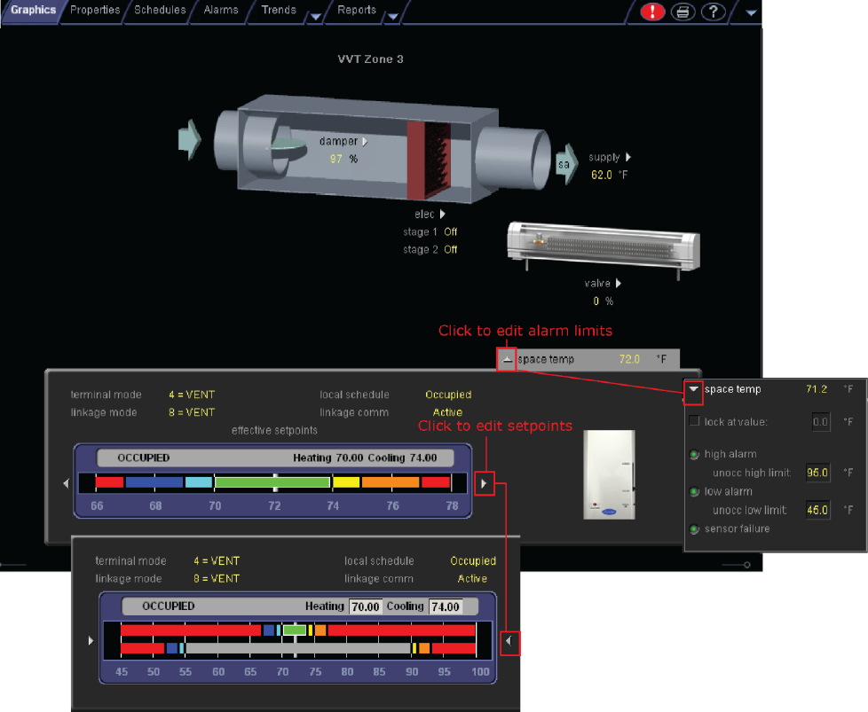
i-Vu Pro v7.0 Help CARRIER CORPORATION ©2020
All rights reserved
39
Adjust setpoints
Programmed setpoints are set and changed by operators.
Effective setpoints reflect the impact of other system conditions on the programmed setpoints, such as
setpoint adjustments, and hysteresis. Effective setpoints control the equipment.
To change programmed setpoints:
1 Navigate to a setpoint control in one of the following places:
○ Properties page > Control Program tab > Configuration > Setpoints
○ The setpoint microblock pop-up on a Logic page
○ A Graphics page (Click a setpoint trend graph control to access the editable setpoint bar.)

i-Vu Pro v7.0 Help CARRIER CORPORATION ©2020
All rights reserved
40
2 Make changes on a programmed setpoint bar by either:
○ Clicking and dragging the segment or the gap between segments
○ Typing new values in the Heating and Cooling fields
3 Click Accept.
Demand Control
Demand Control is a cost-saving strategy that saves energy while maintaining comfort in the following ways:
Controlling energy use to avoid peak demand, ratchet, or time of use utility charges
Maintaining ventilation at relaxed setpoints rather than shutting down equipment (as with load shedding or
duty cycling)
Before you can use Demand Control effectively, you must:
Obtain details regarding past energy usage and peak demand, ratchet, and time of use charges from your
energy provider.
Understand the demand profiles of the zones you are controlling.
Demand Control can be customized at the zone level. For example, you may relax the setpoints in some zones, like
break rooms and closets, by a few degrees, but you may not want to relax setpoints in computer rooms at all.
To define Demand Control properties
1 On the navigation tree, select the electric meter.
2 Select Properties > Control Program and expand the Demand Level Parameters section.
3 Type the Start and End time to define the time period that you want demand control to be in effect for this
zone.
4 Type kilowatts per hour (kW/hr) in the Level columns to define the amount of power that the demand must
exceed before the i-Vu® Pro system calls for a higher demand level.

i-Vu Pro v7.0 Help CARRIER CORPORATION ©2020
All rights reserved
41
NOTE Levels are defined in the electric meter control program in the Snap application. You can test the Demand
Levels by locking the meter to a value.
In the example below, during Period 4, defined as 12:00 (noon) to 16:00 (4:00 p.m.), if the demand exceeds 800
kW/hr, the i-Vu® Pro system will use Demand Level 1 setpoints. If the demand exceeds 1000 kW/hr, the i-Vu® Pro
system will use Demand Level 2 level setpoints and so on.
Configuring Optimal Start
Enable and configure Optimal Start on the Properties page > Control Program tab > Configuration > Setpoints.
Your control program could be configured for Optimal Start or for both Optimal Start and Optimal Start Type.
NOTES
The Optimal Start options depend on the revision date of the control program in your controller.
Optimal Start is automatically disabled when Properties > Control Program > Maintenance > Occupancy >
BAS On/Off is set to either Unoccupied or Occupied.
Optimal Start
Optimal Start adjusts the effective setpoints to achieve the occupied setpoints by the time scheduled occupancy
begins.The Optimal Start recovery period may begin as early as 4 hours prior to occupancy. The algorithm works by
moving the unoccupied setpoints toward the occupied setpoints. The rate at which the setpoints move is based on
the outside air temperature, design temperatures, and capacities.
The following conditions must be true for optimal start to operate:
On the Properties page > Control Program tab > Configuration > Setpoints > Optimal Start, the Default Value
must be set greater than 0 and less than or equal to 4 (0.00 disables Optimal Start).
The system is unoccupied
NOTE If the Open controller does not have a valid outside air temperature, then a constant of 65° F is used. This
value is not adjustable.

i-Vu Pro v7.0 Help CARRIER CORPORATION ©2020
All rights reserved
42
The actual equation that the controller uses to calculate Optimal Start is nonlinear. An approximation of the result
is shown below.
To change Optimal Start settings:
1 In the navigation tree, select the equipment that you want to change.
2 Select Properties page > Control Program tab > Configuration > Setpoints.
Optimal Start Type
If you have Optimal Start Type, you must choose from the following:
None
Temperature Compensated Optimal Start
Learned Adaptive Optimal Start
To select the method used to change from unoccupied to occupied setpoints:
1 In the navigation tree, select the equipment that you want to change.
2 Click Properties page > Control Program tab > Configuration > Setpoints.
3 Select option from the Optimal Start Type drop-down list.
4 See below to make further adjustments.
None – The unit will not start to control to the occupied setpoints until the unit goes into an occupied mode.
Setpoints do not ramp, but change immediately from unoccupied to occupied values. When you select None, you
must set all Learning Adaptive Optimal Start transition factors, identified by their themographic color, to 0. These
are located directly above the Effective Set Points graph.
i-Vu Pro v7.0 Help CARRIER CORPORATION ©2020
All rights reserved
43
Temperature Compensated – The unit changes to occupied setpoints at some time prior to the occupied time, not
to exceed the hours you set for Optimal Start. The start time is determined by the current error between space
temperature and the appropriate heating or cooling setpoint. At that time, the setpoints do not ramp, but change
immediately from unoccupied to occupied values. When selecting Temperature Compensated, you must set all
Learning Adaptive Optimal Start transition factors, identified by their thermographic color to 0. These are located
directly above the Effective Set Points graph.
When selecting Temp Compensated, you can adjust the following:
Heat Start K factor (min/deg) – If Optimal Start Type is Temp Compensated, this is the time in minutes per
degree that the equipment starts before the occupied period when the space temperature is below the
occupied heating setpoint (including any setpoint offset).
Cool Start K factor (min/deg) – If Optimal Start Type is Temp Compensated, this is the time in minutes per
degree that the equipment starts before the occupied period when the space temperature is above the
occupied cooling setpoint (including any setpoint offset).
NOTE The default value for the above is 15.00 and the range is 0 to 99.
Learning Adaptive Optimal Start – This function gradually adjusts the unoccupied setpoints over a specified period
of time to achieve the occupied setpoint by the time scheduled occupancy begins. This learning adaptive algorithm
uses the learned heating capacity and learned cooling capacity values to calculate the effective setpoints prior to
the occupied start time. The algorithm calculates a learned cooling and heating capacity during the previous
unoccupied time. Set the Learning Adaptive Optimal Start recovery period from 1 to 4 hours in Optimal Start.
When the Learning Adaptive Optimal Start routine runs, adjustments are based on the color that is achieved when
occupancy begins. Adjustment amounts are defined in the thermographic color fields located directly above the
Effective Setpoints graph under Setpoints.
EXAMPLE The heating capacity for a zone is 5° per hour (default). When the zone becomes occupied, the zone
temperature is 1° below the occupied setpoint, indicating a need for additional heat. Because the zone
temperature was low by 1°, the learned heating capacity is decreased by the value entered in the LtBlue
thermographic color field (0.0600 default). As a result, the learned heating capacity is adjusted to 4.94° for the
next optimal start period. Since the algorithm has calculated that the equipment has less capacity to bring the
temperature to setpoint within the configured recovery period, the setpoint adjustment begins sooner in the next
unoccupied period.
To change the adjustment values in the Learning Adaptive Optimal Start routine:
1 In the navigation tree, select the equipment that you want to change.
2 Click Properties page > Control Program tab > Configuration > Setpoints.
3 Adjust the color fields between the Zone Setpoints graph and the the Effective Setpoints graph.
When you determine that no further start time optimization is required, you can disable Heating and Cooling
Capacity adjustments by setting the color field values to 0.0.

i-Vu Pro v7.0 Help CARRIER CORPORATION ©2020
All rights reserved
44
You can reset the learned heating and cooling capacities by entering a value into either the Heating Capacity or
Cooling Capacity, located beneath the Zone Setpoints graph.
CAUTION When using Learning Adaptive Optimal Start, be sure that all equipment is properly maintained so
that your system does not “learn” to compensate for dirty filters or loose fan belts.

i-Vu Pro v7.0 Help CARRIER CORPORATION ©2020
All rights reserved
45
Using schedules, your equipment can maintain one set of setpoints during occupied periods to provide comfort,
and it can maintain a different set of setpoints during unoccupied periods to reduce energy consumption.
Schedules are an i-Vu® Pro system's most effective cost-saving strategy.
In the User view, you can apply a schedule to a single tree item or to a group of tree items.
When you apply a schedule to a tree item, the schedule affects equipment
at and below the area or equipment where the schedule was added.
When you apply a schedule to a schedule group, the schedule affects all
pieces of equipment in the group.
For example, a school board meets every third Tuesday of the month and
uses the lobby, main conference room, break room, and restrooms. You
can create a schedule group to control these different areas with a single
schedule.
NOTES
When multiple schedules affect a tree item, the net result is the Effective schedule (page 50).
Do not include preheating or precooling time in your schedules. Optimal Start (page 41), another cost-saving
strategy, automatically calculates and controls precise preheating and precooling routines.
If your system has no need to run schedules, you can turn off this feature. First, delete any existing schedules.
Then go to the System Options (or System Settings) > General tab (page 274), and check the box Disable
Schedules feature.
Schedules

i-Vu Pro v7.0 Help CARRIER CORPORATION ©2020
All rights reserved
46
Creating and modifying schedules
To view schedules
1 Select a navigation tree item (site, area, or equipment).
2 Click Schedules > View tab.
3 Optional: Click a white Effective bar to view all the schedules that contribute to the resulting schedule. If the
item has multiple schedules, the schedule closest to the Effective bar has the highest priority. You set a
schedule's priority when you create the schedule.
NOTES
When multiple schedules affect a single area or controller, the i-Vu® Pro application sorts the schedules by
priority - the higher the priority, the closer the schedule is to the bar. You set a schedule's priority when you
add a schedule.
You can also view schedules on the following detailed, printable schedule reports. These reports are
accessible from the Schedules page > Reports tab or from the Reports button drop-down menu.
This report...
allows you to...
Schedule Instances
Find every schedule with its location that is entered at and below a selected tree
item. This report can help you discover newly added and conflicting schedules.
Effective Schedules
View all equipment that may be scheduled and the net result of all schedules in
effect for a selected date and time. See Effective schedules (page 50).
To print schedules
1 Select a navigation tree item and click Reports .
2 Click Schedules > Schedule Instances or Effective Schedules.
3 Click Run, then click PDF.
This report...
allows you to...
Schedule Instances
Find every schedule with its location that is entered at and below a selected tree
item. This report can help you discover newly added and conflicting schedules.
Effective Schedules
View all equipment that may be scheduled and the net result of all schedules in
effect for a selected date and time.

i-Vu Pro v7.0 Help CARRIER CORPORATION ©2020
All rights reserved
47
To apply a schedule to equipment
Schedules in the i-Vu® Pro application are typically based on zone occupancy.
1 In the User navigation tree, select the area or equipment you want to schedule.
NOTES
○ To schedule all equipment in a specified area, select the area you want.
○ You can schedule individual controllers from the Installer view, but you must be in the User view to
schedule areas and routers
2 Click Schedules, then Configure tab.
3 Click Add.
4 Select a Priority. A schedule's priority determines whether affected zones will use occupied or unoccupied
setpoints.
Select...
For...
Normal
A typical occupied period
Holiday
An unoccupied period that overrides a Normal schedule
Override
An occupied period that overrides a Holiday schedule
5 Select a Type. See table below.
6 Type a schedule name in the Description field (50 characters maximum).
7 Enter desired values in the fields below Description.
8 On the graph, change a time segment's Start and End times by doing one of the following:
○ Click the segment, then type the times in the Start and End fields.
○ Click and drag either end of the segment or the entire segment.
9 Optional: Click Add Time Period to add one or more segments to the schedule. Or, select a segment and click
Delete Time Period to delete that segment.
10 Click Accept.
Select this Type...
To use the schedule...
Weekly
Every week on the specified days
Date
On a single, specified date
Date Range
Between 2 specified dates
Date List
On multiple, specified dates
Wildcard
According to a repeating pattern (For example, the second Tuesday of every
month)
Continuous
Continuously between specified times on 2 separate dates

i-Vu Pro v7.0 Help CARRIER CORPORATION ©2020
All rights reserved
48
Select this Type...
To use the schedule...
Dated Weekly
Weekly between a start date and an end date (For example, the summer break in
the school year)
NOTES
To automatically download all schedules that you create or change, click > System Options > My
Settings and, under Preferences, select Automatically download schedules on each change. If you want to
manually download schedules, clear the Automatically download... field and then see Downloading system
changes to controllers (page 257).
When you apply a schedule to an item on the navigation tree, the schedule affects that item and all children of
that item. If you do not want an item to be affected by schedules from a higher level, select Ignore Schedules
above this level on the Schedules > Configure tab.
To apply a schedule to a group of items
You must create a group, then add members (areas, equipment, or other groups) to the group before you can apply
a schedule to it.
1 On the User navigation tree, select Scheduling Groups.
Optional: If you have created folders to organize your groups, select the appropriate folder. See "To organize
groups using folders" below.
2 Click Add Group.
3 Type a name for the new schedule group in the Name field.
4 Optional: Change the default Reference name. A group's reference name must be unique throughout the
system.
5 Click Accept.
6 Click Add Members to Group.
7 On the Members page, select the areas, equipment, or other groups that you want to add to the group from
the tree on the right. Use Ctrl+click, Shift+click, or both to select multiple items.
8 Click Add.
TIP Use the Raise and Lower buttons to reorder items in the Members list. Changing the order is for your
viewing convenience and does not affect the system.
9 Click Accept.
10 You will see the question Execute download now?. Click OK.
11 Click the Schedules button, then Configure.
12 Add a schedule to the group. See To apply a schedule to equipment (page 47).
i-Vu Pro v7.0 Help CARRIER CORPORATION ©2020
All rights reserved
49
To organize groups using folders
You can create folders and sort your groups into them to organize the Schedule Groups tree. For example, a large
school system that has a group for each school may want to create an Elementary School folder, a Middle School
folder, and a High School folder, and put the appropriate groups in each folder.
To create folders and add groups to them:
1 On the User tree, select Scheduling Groups.
2 Click Add Folder.
3 Type a name for the new folder in the Name field.
4 Optional: Change the default Reference name.
5 Click Accept.
6 Repeat steps 1–4 for each folder that you want to add.
7 Do one of the following to add a group to a folder:
○ If you have already created the group, drag and drop it into the appropriate folder in the tree on the
Scheduling Groups page, then click Accept.
○ Select the folder in the tree on the Scheduling Groups page, then click Add Group to add a new group
inside the folder.
NOTE You can also add a folder to a folder, or drag and drop a folder into another folder.
To edit or delete a schedule
1 Do one of the following:
○ On the navigation tree, select the tree item where the schedule was defined, then select Schedules >
Configure tab.
○ In the User tree, click Scheduling Groups, then select the group that has the schedule you want to edit or
delete.
2 Select the schedule you want to edit or delete.
3 Edit the fields you want to change or click Delete.
4 Click Accept.
NOTE Expired dated schedules are automatically deleted from the database at 3:30 AM every day. But expired
schedules remain in the controller until the next time schedules are downloaded to the controller.

i-Vu Pro v7.0 Help CARRIER CORPORATION ©2020
All rights reserved
50
Effective schedules
The effective schedule that you see on the Schedules > View tab can be the result of multiple overlapping
schedules.
The following schedule features can influence an item's effective schedule.
Feature
Description
Hierarchy
A schedule applied to an item on the i-Vu® Pro tree affects that item and all of its children. A child
item's combined schedule could be the result of multiple schedules applied at different levels above
it. To change a child item's combined schedule:
Add a schedule at the child that overrides the current schedule. See the Priority feature below.
Set the child to ignore the parent schedules. To do this, select the child item on the tree, then go
to Schedules > Configure. Select the schedule, then click Ignore Schedules above this level. You
can then add a different schedule for the child.
Any schedule change that you make to an item affects it and all of its children.
Priority
You must assign one of the following priorities to every schedule.
Use...
For...
Normal
A typical occupied period
Holiday
An unoccupied period that overrides a Normal schedule
Override
An occupied period that overrides a Holiday time
EXAMPLE For a school, you define:
A Normal schedule that has it occupied every Monday–Friday, 6 am–5 pm
A Holiday (unoccupied) schedule for the week of Spring Break
An Override schedule on the first day of Spring Break from 9 am–1 pm for the cafeteria only
where a teacher's meeting will be held.

i-Vu Pro v7.0 Help CARRIER CORPORATION ©2020
All rights reserved
51
Feature
Description
Type
You must assign one of the following types to every schedule.*
Weekly
Date
Date Range
Date List
Wildcard
Continuous
Dated Weekly
See To apply a schedule to equipment (page 47) for a description of each type.
EXAMPLE For a school, you define the following 3 schedules:
Full calendar year: Normal, Weekly, Monday–Friday, 6am–5pm
Summer months: Holiday, Continuous, 12am June 1st –11:59pm August 31st
Work days in summer months: Override, Dated Weekly, Monday–Thursday, 9am–2pm
Using the Priority and Type options, you can often accomplish the combined schedule you need in several different
ways. For example, the combined schedule resulting from the 3 schedules described above for Type could also be
accomplished with the following schedules:
School year: Normal, Dated Weekly, Monday–Friday, September 1st–May 31st, 6am–5pm
Summer months: Normal, Dated Weekly, Monday–Thursday, June 1st–August 31st, 9am–2pm
Using schedule categories
Occupancy is the only default schedule category. It is a binary schedule category that allows a zone or piece of
equipment to be defined as On when a space is occupied and Off when it is unoccupied.
You can add custom schedule categories to handle other conditions if the equipment’s control program includes
one of the following microblocks:
Carrier Schedule
Carrier Schedule with TLO and Override Status
BACnet Time Clock with TLO and Override Status
BACnet Modeled Schedule
Creating a custom schedule category
1 Create the custom schedule category in the Snap application. See "To use custom alarm and schedule
categories" in Snap Help.
2 In the Snap application, select the new category from the Schedule Category droplist in a the schedule
microblock.
3 Create the same custom schedule category in the i-Vu® Pro interface. The Reference Name must be identical
to the category's name in the Snap application. See "To add a custom schedule category in the i-Vu® Pro
interface" below.

i-Vu Pro v7.0 Help CARRIER CORPORATION ©2020
All rights reserved
52
To add a custom schedule category in the i-Vu® Pro interface
TIP Study the default Occupancy category to understand the various properties you need to set when adding a
new schedule category.
PREREQUISITES
Add the custom schedule category in the Snap application. See "To use custom alarm and schedule
categories" in Snap Help.
In the Snap application, select the new category from the Schedule Category droplist in a Time Clock
microblock.
1 On the System Options tree, click to the left of the Categories folder, then click Schedule.
2 Click Add.
3 Enter values or add items for the fields in each section of the page. See table below.
NOTE The fields that you see depend on selections you made in previous sections.
4 Click Accept.
Field
Notes
Category Name
The name used in the i-Vu® Pro interface
Reference Name
Must be unique in the database, be lowercase, and not contain any
spaces.
This name must be identical to the name of the custom schedule
category that you added in the Snap application.
Do not use occupancy as the reference name.
Allowed Type
Replace Undefined with one of the following:
Boolean: binary (on/off, true/false) condition
Multi State: list of integer-defined states. For example, 1=off, 2=on,
3=dim
Default Value
Displays what schedule value is in effect for times not specified by the
schedule. To set this value, in the Allowed Values table, select the value
that you want to use as the default, then click the Make Default OK
button.
Allowed Values
If you selected Boolean above, select True Value or False Value.
If you selected Multi State, click the Add Value button to create each
schedule state.
Allowed Value Description
The name used in the i-Vu® Pro interface.

i-Vu Pro v7.0 Help CARRIER CORPORATION ©2020
All rights reserved
53
Field
Notes
Pattern
Type none, dark, or
/_common/lvl5/graphics/patterns/xxx.gif,
where xxx.gif is any .gif file in the
webroot\_common\lvl5\graphics\patterns folder.
Priority Description
The name used in the i-Vu® Pro interface.
Index
Represents this priority’s relative level of importance within this schedule
category. The i-Vu® Pro application automatically assigns the priority
index, which is zero for the first priority level. The higher the index value,
the higher the priority of the schedule type relative to other schedules.
BACnet limits the number of priority indices to 16.
Color
Color of the schedule bar on the Schedules page.
Schedule Types
The Weekly type is available for Index 0 only.
The Allow Wildcards and Partial Day options affect all selected schedule
types.
Default Schedule
The default schedule used when this category is selected. Create the
schedule by adding segments for each state until every hour in the 24-
hour schedule is covered by a segment.
EXCEPTION If you selected Partial Day in the Schedule Types field, you
do not have to add segments for the entire 24-hour period.
To view, edit, or delete a schedule category
1 On the System Options tree, click to the left of the Categories folder, then click Schedule.
2 In the table, select the category you want to edit or delete.
3 Edit the fields or click Delete.
4 Click Accept.
i-Vu® Pro CCN schedules
There are 2 types of CCN schedules:
1 – 64 are local schedules that reside within the equipment
65 – 99 are network or global schedules, which are sent over a CCN network and received by controllers that
contain network schedules

i-Vu Pro v7.0 Help CARRIER CORPORATION ©2020
All rights reserved
54
The i-Vu® Pro application supports both local and global schedules.
Most CCN equipment is shipped with the default schedule of 64. See exceptions below.
Equipment
i-Vu® Pro's default
schedule number
Comfort Controller/UC/Expansion Controllers
0
Any controllers using a custom equipment file (*.equip)
created with EquipmentBuilder
0
Gen III VVT, 48/50EJ (Conquest), FSM, CSM
1
All PICs
64
CAUTION! Confirm the actual schedule numbers that are used in the controller, as they may have been
changed from their programmed default settings.
In order to use i-Vu® Pro schedules, the i-Vu® Pro schedule number must match the CCN schedule number at the
controller. This can be set in the i-Vu® Pro interface by selecting the equipment in the navigation tree and clicking
Schedules > CCN tab. It is also accessible at the area or site level.
NOTE To reduce start-up labor on a retrofit project, existing network schedules can be used by the i-Vu® Pro
application. However, switching to local schedules allows for schedule retention after a power failure and local
schedule maintenance tables.
If a controller uses a different schedule number, complete the following steps.
CAUTION! Failure to follow these steps may result in unexpected equipment operation.
1 On the navigation tree, select the controller.
2 Click the Schedules page, then CCN tab.
3 Adjust the following fields:
Schedule number - enter the CCN schedule number in use at the controller.
Override time (optional) - enter the number of minutes of the desired override and verify that the controller
override time is greater than or equal to this number
Override group - enter the number of the group, if you have established one

i-Vu Pro v7.0 Help CARRIER CORPORATION ©2020
All rights reserved
55
The i-Vu® Pro system can read and store equipment status values over time and then display this information in a
trend graph to help you monitor the equipment’s operation.
You can collect trend data for any point value in the i-Vu® Pro system. The controller reads point values at intervals
that you define and then stores that data in the controller. A controller has limited memory for storing trend data,
so you can set up historical trending to archive the trend data from the controller to the i-Vu® Pro database. A
trend graph can display data from the controller and the database, or it can display only data stored in the
database.
After you set up the desired points for trend data collection (page 56), you can:
View built-in trend graphs that show a single point (page 58)
Create custom trend graphs with multiple points (page 58)
Trends

i-Vu Pro v7.0 Help CARRIER CORPORATION ©2020
All rights reserved
56
To collect trend data for a point
Before you can see a point's trend graph, you must enable trending for that point and then define how you want
the controller to collect the point's data. This can be done in Snap or you can do it in the i-Vu® Pro interface using
the instructions below.
NOTE I/O microblocks have trending capability built-in, and you enable trend logging in the I/O microblock. Any
other microblock value must have a trend microblock attached in the control program, and you enable trend
logging of the value in the trend microblock.
To set up a point's trending in the i-Vu® Pro interface:
1 On the navigation tree, select the equipment that has the point you want to trend.
2 Click the Trends button drop-down arrow, select Disabled Points, then select the point.
3 Click the Enable/Disable tab, then select Enable Trend Log to have the controller collect trend data.
4 Enter information in the appropriate fields. See table below.
5 Click Accept.
TIP You can set up all trends for a piece of equipment at once on the Trend Sources tab of the equipment's
Properties page.
Field
Notes
Sample every _:_:_ (hh:mm:ss)
Records the point’s value at this interval.
NOTES
Set this field to one minute or greater.
This setting should be longer than the CCN bus poll interval. To
determine the poll interval:
1. In the Installer tree, right-click the device polling the CCN
controller, and then select Driver Properties.
2. Go to Protocols > CCN.
3. Scroll down to the Program Status heading.
4. In the first row of the table, subtract the third column
value from the fourth column value to get the poll interval.
Sample on COV
(change of value)
Records the point’s value only when the value changes by at least the
amount of the COV Increment.
NOTE Use this method for a binary point or for an analog point that has
infrequent changes in value.

i-Vu Pro v7.0 Help CARRIER CORPORATION ©2020
All rights reserved
57
Field
Notes
Allocate memory for __ trend
samples in the controller
The maximum number of samples that you want the controller to store.
CAUTION Changing the value in Allocate memory for __ trend samples in
the controller will delete all of the point's trend samples currently stored in
the controller. Click the Store Trends Now button before changing the value
to transfer the trend data from the controller to the system database.
NOTES
Trending consumes memory in the controller. The amount of memory
available depends on the type of controller. Each trended point
consumes 48 bytes of memory plus 10 bytes for each trend sample.
Each trend microblock consumes 416 bytes of memory plus 10 bytes for
each trend sample.
Click Reset to delete all samples currently stored in the controller.
The above sample and memory allocation fields together define trend data storage in the controller in terms of
hours.
EXAMPLE If you set these fields so that samples are collected every 5 minutes for a maximum of 120 samples,
the controller will store 600 minutes (5 x 120) or 10 hours of trend data.
Stop When Full
Check this field to stop trend sampling when the maximum number of
samples is reached.
Enable trend log at specific
times only?
Collects trend data for the specific period of time you define in the time and
date fields.
Enable Trend Historian
Archives trend data to the system database.
Store Trends Now
Writes all trend data in the controller to the system database without having
to enable trend historian.
Every __ trend samples write to
historian
Writes all trend data in the controller to the system database each time the
controller collects the number of samples that you enter in this field. This
number must be greater than zero and less than the number entered in the
field Allocate memory for __ trend samples in the controller. The number of
trends specified must be accumulated at least once before the historical
trends can be viewed.
Trend samples accumulated
since last notification
Shows the number of samples stored in the controller since data was last
written to the database.
Last Record Written to Historian
Shows the number of trend samples that were last written to the database.
Keep trends for __ days
This is based on the date that the sample was read. Select the first option to
use the system default that is defined on the System Settings > General tab.
Select the second option to set a value for this trend only.
Delete
Deletes all trend samples stored in the database for the item selected on the
navigation tree.
BACnet Configuration
The Object Name is a unique alphanumeric string that defines the BACnet
object. Although the Object Name field can be edited, it is not recommended.
The Notification Class is set to 1 to receive alarms generated by Carrier
controllers.

i-Vu Pro v7.0 Help CARRIER CORPORATION ©2020
All rights reserved
58
NOTES
You can use Global Copy (page 28) to copy trend properties to other pieces of equipment that use the same
control program.
Run a Trend Usage report (page 98) to view trend configurations.
Viewing a built-in, single-point trend graph
1 On the navigation tree, select the equipment whose trend you want to view.
2 Click the Trends button drop-down arrow, select Enabled Points, and then select the graph you want to view.
3 Select the View tab. See Using trend graphs (page 61).
NOTE On the Configure tab, you can:
Enable/disable the grid.
Set the time range for the X axis. For example, enter 7 days to see the data for the last week.
Turn off autoscaling so that you can define a range for the Y-axis
Type a Y-axis label that will appear on the right side of the graph.
Creating a custom trend graph
When creating a custom trend graph, you can select up to 16 points. If you select more than 4 points or points with
different units, the i-Vu® Pro application splits the data into subgraphs. Each subgraph can show a maximum of 4
points with similar units.
NOTE You must enable trending for points that you want to include in the custom trend graph. See To collect trend
data for a point (page 56).
i-Vu Pro v7.0 Help CARRIER CORPORATION ©2020
All rights reserved
59
To create a custom trend graph
1 On the navigation tree, select the area or equipment where you want to see the graph.
2 Click the Trends button drop-down arrow, then select New Trend Graph.
NOTE If the Trends button does not have a drop-down arrow, the New Trend Graph page is already displayed.
3 In the tree on the New Trend Graph page, use Ctrl+click or Shift+click to select the points (16 maximum) that
you want to see on a graph.
NOTE The tree shows only points that have trending enabled. See To collect trend data for a point (page 56).
4 Click Save.
5 Optional: If your system has trend categories defined, you can select a Category for this trend. For more
information on trend categories, see Adding trend categories (page 60).
6 Type a Name for the graph that will appear at the top of the graph and in the Trends button drop-down list.
7 Click OK.
8 Select:
○ The View tab to see the custom trend graph. See Using trend graphs (page 61).
○ The Configure tab to edit the trend graph. See To edit a custom trend graph (page 59).
To edit a custom trend graph
1 On the navigation tree, select the area or equipment where you created the graph.
2 Select the Trends > Configure tab. On this page, you can:
Change the name of the custom trend graph
Enable/disable the grid
Set the time range for the X axis
Edit a subgraph's Y-axis label that will appear on the right side of the graph
Turn off autoscaling so that you can define a range for the Y-axis
Add/delete subgraphs (see instructions below)
Add/delete points (see instructions below)
Change a point's name on the graph
Change a binary point's active/inactive text on the graph
Click Delete Trend Graph to delete the entire custom trend graph
To add a subgraph to a custom trend graph
1 Click Add below the Subgraphs list.
2 Type a Y-axis label.
3 Click Add below the Points list.
4 Select a point in the Data source tree.
NOTE The tree shows only points that have trending enabled. See To collect trend data for a point (page 56).

i-Vu Pro v7.0 Help CARRIER CORPORATION ©2020
All rights reserved
60
5 Repeat steps 3 and 4 to add up to 4 points to the subgraph.
6 Click Accept.
NOTE To delete a subgraph, select it in the Subgraphs list, click Delete below the list, and then click Accept.
To add a point to a subgraph
1 Select the subgraph in the Subgraphs list.
2 Click Add below the Points list.
3 Select a point from the Data source tree.
NOTE The tree shows only points that have trending enabled. See To collect trend data for a point (page 56).
4 Click Accept.
NOTE To delete a point, select the appropriate subgraph, select the point, click Delete below the Points list, and
then click Accept.
Adding trend categories
A point trend graph is in the Enabled or Disabled category in the Trends button drop-down menu.
You can create additional categories for your custom trend graphs.
1 On the System Options tree, click to the left of Categories, then select Trend.
2 Click Add.
3 Type the Category Name and Reference Name.
4 Optional: Select a privilege so that only operators with that privilege can access trends in the category.
5 Click Accept.
NOTES
To edit a category, select the category, make your changes, then click Accept.
To delete a category, select the category, click Delete, then click Accept.

i-Vu Pro v7.0 Help CARRIER CORPORATION ©2020
All rights reserved
61
Using trend graphs
NOTES
A gray triangle at the top of a graph indicates a note from the system. Hover your cursor on the triangle to see
which of the following occurred:
○ Equipment received a time synchronization from its network router or from the i-Vu® Pro application.
○ Trend Historian has been enabled or disabled.
○ Trend Log has been enabled or disabled.
○ The trend object ID of a third-party trend source has been changed. For information only, you do not need
to do anything.
Click at the top of the i-Vu® Pro page to print the graph. You may need to set your printer's orientation
to Landscape.
Toolbar options are also accessible by right-clicking a trend graph.
You can check Display gap in graph line for missing data on an individual trend graph page, or you can go to
the System Options (or System Settings) > General tab (page 274) to set this for all future trend graphs.

i-Vu Pro v7.0 Help CARRIER CORPORATION ©2020
All rights reserved
62
To view trend data in a spreadsheet program
You can save trend data as csv data that you can open in a spreadsheet program such as Microsoft® Excel®.
1 On the Trends > View tab, select > Save as CSV data.
2 Save the data (.zip file) wherever you want. The .zip file contains the following:
A .csv file for each trend source (point). The filenames match the point names.
A Combined folder containing a file with the combined data for all of the graph's trend sources.
3 Open the .csv file in a spreadsheet program.
NOTES
You will need to convert the data in the spreadsheet's Time column to a readable date/time format.
If you use Microsoft® Excel® on a Mac and the converted date shows the wrong year, do the following:
1. In Excel, go to File > Options > Advanced.
2. Scroll down to the section When calculating this workbook, and then uncheck Use 1904 date system.

i-Vu Pro v7.0 Help CARRIER CORPORATION ©2020
All rights reserved
63
A message is sent from an alarm source to i-Vu® Pro to notify you that certain conditions exist, such as a piece of
equipment that has stopped running or a temperature that is too high. When i-Vu® Pro receives an alarm, it
displays information about the alarm on the Alarms page. i-Vu® Pro can also perform alarm actions (page 69) to
inform personnel of the condition. An alarm source can also send a return-to-normal message when the alarm
condition returns to its normal state.
Alarm sources and the alarms they generate are assigned to categories, such as HVAC Critical or HVAC
Maintenance, to help you work with related alarms.
The application engineer usually sets up alarm sources in the Snap application. In the i-Vu® Pro interface, you can:
View, troubleshoot, acknowledge, and delete alarms (page 64)
Set up the alarm actions that the i-Vu® Pro application performs (page 69)
Edit alarm sources that were set up in the Snap application or set up new alarm sources to generate alarms
(page 89)
NOTE In addition to the alarms that you set up, i-Vu® Pro has built-in system and equipment alarms.
Alarms

i-Vu Pro v7.0 Help CARRIER CORPORATION ©2020
All rights reserved
64
Viewing, acknowledging, and deleting alarms
The i-Vu® Pro Alarms page displays alarms as they are received. If desired, an operator can set options on >
System Options > My Settings tab to have the i-Vu® Pro application play an audio file when an alarm is received.
An alarm's setup may require that it be acknowledged and/or the alarm condition returned to normal. The alarm,
its return to normal, and any other alarms related to the incident are referred to as an alarm incident group. The i-
Vu® Pro application closes an alarm incident group when all of the following have occurred:
You acknowledge the alarm (if required)
The i-Vu® Pro application receives a return-to-normal (if required)
The i-Vu® Pro application performs all alarm actions defined for the group
You should delete alarms from your system as they are closed because large quantities of stored alarms can
reduce the efficiency of your system.
NOTE The Installer view does not display all alarms on the system or site level, only on the router and controller
level. Go to the User view or click the system-wide alarms button to see all of the alarms in the system.
The color of the system-wide alarms button signifies one of the following conditions:
Red - Critical alarms need to be acknowledged.
Yellow - Non-critical alarms need to be acknowledged.
Gray - No alarms need to be acknowledged.
You must acknowledge alarms that have been set up to require acknowledgement. Right-click alarm message to
print. To save alarm information before deleting, select Alarms > Reports tab > Alarms > click Run button.
To view alarms in the i-Vu® Pro interface
Click at the top of the page to see all alarms in the system.
or
Click the Alarms button and then select an item on the navigation tree to see all alarms at and below that
level.

i-Vu Pro v7.0 Help CARRIER CORPORATION ©2020
All rights reserved
65
NOTES
Alarms generated by the i-Vu® Pro application appear at the system level.
Alarms generated by controllers appear at the system level in the User view.
An alarm's details include a path to the alarm source. Each section of the path is a link to that location. For
example, in the path West TEMP LO at Router 41/Sunshine Corp, TEMP LO links to the microblock's
Properties page, and Sunshine Corp links to the Sunshine Corp West Wing graphic, TEMP-LO links to the
equipment graphic.
You may see any of the following alarms icons in i-Vu® Pro.

i-Vu Pro v7.0 Help CARRIER CORPORATION ©2020
All rights reserved
66
Access control Red = Critical
Blue = Maintenance
Gray = General
Grayed out = Closed
These icons... Indicate...
Fire system
Lighting system
General alarm
System
Unknown
FDD
General message
Controller alarm
HVAC
Icon color indicates...
FDD comfort
FDD energy
To control which alarms you see
Use these tools...
To control the Alarms list
Click the arrow buttons to display other alarms.
Type a date and time or click to select a date. Then
click Go to show up to 50 alarms since that date/time.
When finished, click to display the 50 newest alarms
or to display the oldest 50 alarms.

i-Vu Pro v7.0 Help CARRIER CORPORATION ©2020
All rights reserved
67
Use these tools...
To control the Alarms list
Date–Sorts list by date/time the alarms were generated
with the most recent at the top.
To Do–Shows only alarms that require one or more actions
before they are closed.
Incident Group–Sorts alarms by incident. For example, an
alarm and its return-to-normal form an incident group.
Brackets indicate a group.
Select the alarm categories that you want to see in the
alarms list. Use Ctrl+click, Shift+click, or both to select
multiple categories, or check Show all categories.
To acknowledge alarms
You must acknowledge alarms that have been set up to require acknowledgment. An alarm shows if it needs to be
acknowledged.
The table in the upper left corner of the page shows how many alarms need acknowledgment at the current
location (Here) and in the entire system (Total). This table also shows how many alarms need a return-to-normal
and how many are closed.

i-Vu Pro v7.0 Help CARRIER CORPORATION ©2020
All rights reserved
68
To acknowledge an alarm
1 On the Alarms page > View tab, select the checkbox of an alarm that shows Acknowledge.
2 Click the Acknowledge button.
To acknowledge all alarms in the alarms database for selected categories
1 On the Alarms page > View tab in the left-hand column, select the categories whose alarms you want to
acknowledge.
NOTE Use Ctrl+click, Shift+click, or both to select multiple categories, or select the Select All checkbox.
2 Click Advanced.
3 Click Acknowledge All.
TIP Acknowledging many alarms simultaneously can take a long time. Acknowledge alarms as they occur to
avoid long waits.
To delete alarms
You should delete alarms from your system as they are closed because large quantities of stored alarms can
reduce the efficiency of your system. To save alarm information before deleting, select Alarms > Reports tab >
Alarms, then click the Run button.
To delete an alarm
1 On the Alarms page > View tab, select an alarm's checkbox.
2 Click Delete.
To delete all alarms in the alarms database for selected categories
1 On the Alarms page > View tab in the left-hand column, select the categories whose alarms you want to
delete.
NOTE Use Ctrl+click, Shift+click, or both to select multiple categories, or select the Select All checkbox.
2 Click Advanced.
3 Click Delete All Acknowledged.
To delete all closed alarm incident groups in the alarms database
An incident group is all alarms related to a particular incident. For example, an alarm and its return-to-normal form
an alarm incident group. An incident group is considered closed when all alarms in the group are closed.
1 On the Alarms page > View tab in the left-hand column, select the categories whose alarms you want to
delete.
NOTE Use Ctrl+click, Shift+click, or both to select multiple categories, or select the Select All checkbox.

i-Vu Pro v7.0 Help CARRIER CORPORATION ©2020
All rights reserved
69
2 Click Advanced.
3 Click Delete Closed Incidents.
NOTES
An alarm that requires acknowledgement cannot be deleted until it has been acknowledged.
To have the i-Vu® Pro application automatically delete alarm incident groups a specified number of days after
the groups close, select this option on the System Settings > Scheduled Tasks (page 281) tab.
Also on the System Settings > Scheduled Tasks tab, you can set the i-Vu® Pro application to archive alarm
information to a text file as alarms are deleted.
An alarm source may be set up to generate an alarm and a return-to-normal. If an alarm occurs but the i-Vu®
Pro application never receives the return-to-normal, you can select the alarm and then click Force Normal so
that the alarm can be closed. Force Normal has no effect on the alarm condition that generated the alarm.
To receive audible notification of alarms
You can set up the i-Vu® Pro application to play an audio file on your workstation when it receives a critical or non-
critical alarm.
1 On the System Options tree, select My Settings.
2 Under Preferences, select Non-critical alarms or Critical alarms to be notified of each type of alarm.
3 In the Sound File field, type the path to the sound file.
When an alarm triggers the audio file to play, you can click and then select:
Snooze to temporarily stop the sound for 5 minutes
Silence to stop the sound
The alarm sound is silenced until another alarm that triggers a sound is received.
Setting up alarm actions
The i-Vu® Pro application can perform alarm actions listed below to notify personnel of an alarm or to record
information about the alarm. You can assign alarm actions to an alarm source, a category of alarm sources, alarm
sources from a certain location, or a combination of these criteria.
The alarm actions are:
Alarm Popup
Print
Run External Program
Send Alphanumeric Page
Send E-Mail
Send SNMP Trap
Send Web Service Request
i-Vu Pro v7.0 Help CARRIER CORPORATION ©2020
All rights reserved
70
Write Property
Write to Database
Write to File
See the following topics for a description of each alarm action.
To assign alarm actions to alarm sources
To assign alarm actions to multiple alarm sources
Although you can assign an alarm action to a single alarm source, you typically assign an action to multiple alarm
sources at the area or equipment level. The alarm action applies to all instances of the alarm sources at the
selected location and below. Click an action’s Edit button to make any changes.
To assign an alarm action to alarm sources:
1 On the navigation tree, select the area, equipment, or controller containing the alarm sources.
2 On the Alarms page > Actions tab, follow the 3 steps on the screen.
3 Follow the 3 steps on the screen.
NOTE Use Ctrl+click, Shift+click, or both to select multiple items.
4 Click Add.
5 Set up the alarm action by editing the fields on the alarm action page. See the appropriate alarm action below
for field descriptions.
6 Click Accept.
If an alarm action fails, the i-Vu® Pro application receives an alarm for the failed action.
NOTE Click View Selected Sources to view or change settings for each alarm.
To assign an alarm action to a single alarm source
1 On the navigation tree, select the alarm source.
2 On the Alarms page > Actions tab, click the drop-down arrow, then select an alarm action.
3 Click Add.
4 Set up the alarm action by editing the fields on the alarm action page. See the appropriate alarm action below
for field descriptions.
5 Click OK.

i-Vu Pro v7.0 Help CARRIER CORPORATION ©2020
All rights reserved
71
Alarm Popup
The Alarm Popup alarm action pops up a message on any computer with a Windows operating system that is
running the i-Vu® Pro Alarm Notification Client application.
Field
Notes
To Operator
To Group
Select individual operators or operator groups who should receive alarm notification.
Generate alarm if
delivery fails
Check this field to generate a System Info alarm if the popup recipient is not currently
running the Alarm Notification Client application.
Message text
Use punctuation, spaces, or returns to format the text. To add live data to the text,
select field codes (page 93) from the Append Field Code list.
Append Field Code
Add field codes (page 93) to the message text if desired.
Perform Action
By default, the i-Vu® Pro application performs an alarm action when the alarm source
generates an alarm and when it returns to normal. Under Perform Action, you can
choose to run the alarm action:
Only when the alarm source generates an alarm or when it returns to normal.
After a specified amount of time if the alarm has not been acknowledged or has
not returned to normal. Use this option for alarm escalation.
If the alarm occurs during the occupied hours defined for a schedule group or run
if the alarm occurs during the unoccupied hours defined for a schedule group.
EXAMPLE To have one alarm action performed during work hours and a different
alarm action performed after work hours:
1. Create a schedule group (page 48), but do not assign members to it.
2. Create a schedule for the group. Set the occupied hours to be the same as the
work hours.
3. Create the alarm action that is to be performed during work hours. Under
Perform Action, select If schedule group <your new group> is Occupied.
4. Create the alarm action that is to be performed after work hours. Under
Perform Action, select If schedule group <your new group> is Unoccupied.
Using the Alarm Notification Client application
The Alarm Notification Client application must be running on each client computer (Windows only) that should
receive popup notifications. Keep the application minimized to the right side of the Windows task bar. The window
will pop up with a message when an alarm occurs.
Select an alarm message, then click to open the i-Vu® Pro interface displaying the piece of equipment that
generated the alarm. A grayed out alarm indicates that it was acknowledged in the i-Vu® Pro interface.

i-Vu Pro v7.0 Help CARRIER CORPORATION ©2020
All rights reserved
72
If the Alarm Notification Client is set up to play a continuous alarm sound, you can silence an alarm by clicking
Silence!, by pressing Ctrl+S, or by acknowledging the alarm in the i-Vu® Pro interface.
Button
Notes
Opens the i-Vu® Pro interface displaying the equipment that generated the alarm.
NOTES
If i-Vu Pro Server is to use https (SSL), you must do the following to enable communication
between the server and Alarm Notification Client. In SiteBuilder, go to Configure > Preferences
> Web Server. For Enabled Web Server Ports, select Both HTTP and SSL or SSL only. In the
Server Connection field described below, enter the number of the SSL port.
If i-Vu Pro Server is v6.0 and an Alarm Notification Client is an earlier version, you will have to
log in when you click .
Copies the selected alarm information to the clipboard.
Removes the alarm information from the alarm popup list. Removing items from this list has no
effect on the alarms list in the i-Vu® Pro interface.
View information about the server connection.
On this tab...
You define...
Server Connection
The i-Vu® Pro server and port, and the i-Vu® Pro operator name and password
NOTE The default port is TCP 47806. If you change this, you must also
change the Port field in the i-Vu® Pro System Settings. See "To set up the i-Vu
Pro Server application to support Alarm Popup clients" below.
Browse To
The i-Vu® Pro page that you want to see first when browsing to the equipment
Notification
Sounds
If you want to hear a sound when an alarm occurs
Which sound you want to hear for each type of alarm.
NOTE A Connection Failure occurs when the Alarm Notification Client
loses communication with the i-Vu Pro Server application.
Whether you want the sound to continue until silenced
NOTE If multiple types of alarms occur simultaneously, the application plays
the sound of the most critical alarm (Connection Failure first, then Critical,
then Normal).

i-Vu Pro v7.0 Help CARRIER CORPORATION ©2020
All rights reserved
73
To set up the i-Vu Pro Server application to support Alarm Popup clients
1 On the System Options tree, select System Settings.
2 On the General tab, select Enable support for Alarm Notification Clients to connect to this server.
3 If the server has more than one network interface adapter, type in the Restrict to IP Address field the IP
address that the Alarm Notification Client application will connect to. You must specify the same IP address in
the Server field in the Alarm Notification Client.
4 Use the default port or specify a different port. You must specify the same port in the Port field in the Alarm
Notification Client.
5 Click Accept.
NOTE If the Alarm Notification Client application is not on the local network and will access i-Vu® Pro alarms
through a NAT router, you must port forward the TCP port you defined in step 4 above.
To install the Alarm Notification Client application
Follow the steps below on each client computer that should receive alarm popups.
PREREQUISITE Enable support for Alarm Popup client in System Settings. See above topic.
1 On the System Options tree, click Client Installs.
2 Select Alarm Notification Client.
3 Click Run, then follow the on-screen instructions to install the Alarm Notification Client application. After you
click Done, the application starts automatically.
4 In the Settings dialog box, enter appropriate values. You can also click to open this box. See the table above
for a description of each setting.
NOTE You can lock the Settings so that a user cannot edit them. See To lock a client's Settings feature below.
5 Click OK.
6 Minimize the Alarm Notification Client window.
To lock a client's Settings feature
To prevent a user from editing the Settings :
1 Right-click Alarm Notification Client in the Windows Start menu.
2 Select Properties.

i-Vu Pro v7.0 Help CARRIER CORPORATION ©2020
All rights reserved
74
3 On the Shortcut tab, type -lockconfig at the end of the Target path.
Print
The Print alarm action prints alarm information.
Field
Notes
Text Printing
Select to use the i-Vu® Pro server's local dot-matrix printer. Text Printing will not
print to a network printer.
In the Printer Name field, type the computer port that the printer is connected to.
In the Line Width field, type the number of characters to be printed per line.
Prints multiple alarms per page.
Graphics Printing
Select to use the i-Vu® Pro server's default printer (local or network printer).
Prints one alarm per page to the i-Vu® Pro server's default printer.
Text to Print
Use punctuation, spaces, or returns after the entries to format the text.
To add live data to the text, select field codes (page 94) from the Append Field
Code list.

i-Vu Pro v7.0 Help CARRIER CORPORATION ©2020
All rights reserved
75
Field
Notes
Perform Action
By default, the i-Vu® Pro application performs an alarm action when the alarm
source generates an alarm and when it returns to normal. Under Perform Action,
you can choose to run the alarm action:
Only when the alarm source generates an alarm or when it returns to normal.
After a specified amount of time if the alarm has not been acknowledged or
has not returned to normal. Use this option for alarm escalation.
If the alarm occurs during the occupied hours defined for a schedule group or
run if the alarm occurs during the unoccupied hours defined for a schedule
group.
EXAMPLE To have one alarm action performed during work hours and a
different alarm action performed after work hours:
1. Create a schedule group (page 48), but do not assign members to it.
2. Create a schedule for the group. Set the occupied hours to be the same as
the work hours.
3. Create the alarm action that is to be performed during work hours. Under
Perform Action, select If schedule group <your new group> is Occupied.
4. Create the alarm action that is to be performed after work hours. Under
Perform Action, select If schedule group <your new group> is
Unoccupied.
Run External Program
The Run External Program alarm action starts a program or batch file on the server.
NOTE You must be running i-Vu Pro Design Server to set up this alarm action.
Field
Notes
Command Line
The path of the executable file on the i-Vu® Pro server followed by the path of the
output file.
EXAMPLE:
c:\windows\notepad.exe c:\i-Vu Pro\webroot\alarms.txt
Append Field Code
Add field codes (page 93) to the Command Line field.
EXAMPLE:
c:\reports\run_report.bat $Generation_time$$To_State$
This starts a batch file on the server and uses the alarm’s generation time and state
as values.
Synchronize
Tells the i-Vu® Pro application to wait for the external program to finish running before
initiating the next Run External Program alarm action.

i-Vu Pro v7.0 Help CARRIER CORPORATION ©2020
All rights reserved
76
Field
Notes
Perform Action
By default, the i-Vu® Pro application performs an alarm action when the alarm source
generates an alarm and when it returns to normal. Under Perform Action, you can
choose to run the alarm action:
Only when the alarm source generates an alarm or when it returns to normal.
After a specified amount of time if the alarm has not been acknowledged or has
not returned to normal. Use this option for alarm escalation.
If the alarm occurs during the occupied hours defined for a schedule group or run
if the alarm occurs during the unoccupied hours defined for a schedule group.
EXAMPLE To have one alarm action performed during work hours and a different
alarm action performed after work hours:
1. Create a schedule group (page 48), but do not assign members to it.
2. Create a schedule for the group. Set the occupied hours to be the same as the
work hours.
3. Create the alarm action that is to be performed during work hours. Under
Perform Action, select If schedule group <your new group> is Occupied.
4. Create the alarm action that is to be performed after work hours. Under
PerformAction, select If schedule group <your new group> is Unoccupied.
Send Alphanumeric Page
The Send Alphanumeric Page alarm action sends a page to one or more alphanumeric pagers or sends text
messages to cell phones. The pager or phone must be able to accept e-mail.
Field
Notes
To
Type the address(es) that you want to send the alarm to. To enter multiple addresses,
type a space or press Enter after each address.
From
Enter a valid address if required by your mailserver.
Mail Host
The mailserver's address. This can be an IP address or a system name, such as
mail.mycompany.com.
Mail Host Port
Change this field if using a port other than the default port 25.
Mail Host Security
Options
Select the type of security the mailserver uses.
Cleartext – Uses the SMTP protocol to send as clear text over TCP/IP
Secure SSL – Uses SSL, a communication protocol that provides data encryption
Secure TLS – Uses TLS, but does not begin encryption until the i-Vu® Pro
application issues STARTTLS command
Specify Mail User For
Mail Host
Authentication
Select if your mailserver requires a username and password.

i-Vu Pro v7.0 Help CARRIER CORPORATION ©2020
All rights reserved
77
Field
Notes
Send mail as MIME
attachment
Select if your mailserver allows only MIME attachments.
Message Text
Use punctuation, spaces, or returns to format the text. To add live data to the text,
select field codes (page 93) from the Append Field Code list.
Perform Action
By default, the i-Vu® Pro application performs an alarm action when the alarm source
generates an alarm and when it returns to normal. Under Perform Action, you can
choose to run the alarm action:
Only when the alarm source generates an alarm or when it returns to normal.
After a specified amount of time if the alarm has not been acknowledged or has
not returned to normal. Use this option for alarm escalation.
If the alarm occurs during the occupied hours defined for a schedule group or run
if the alarm occurs during the unoccupied hours defined for a schedule group.
EXAMPLE To have one alarm action performed during work hours and a different
alarm action performed after work hours:
1. Create a schedule group (page 48), but do not assign members to it.
2. Create a schedule for the group. Set the occupied hours to be the same as
the work hours.
3. Create the alarm action that is to be performed during work hours. Under
Perform Action, select If schedule group <your new group> is Occupied.
4. Create the alarm action that is to be performed after work hours. Under
Perform Action, select If schedule group <your new group> is Unoccupied.
NOTE You should not assign this alarm action to frequently-occurring alarms as this may cause problems on your
network or the Internet.
To secure mailserver communication using SSL or TLS
Before the i-Vu® Pro application sends an email using SSL or TLS, it requests an SSL certificate from the
mailserver. If the certificate that the i-Vu® Pro application receives is in its list of trusted certificates, it sends the
email. If the certificate is not in the list, the i-Vu® Pro application generates a system alarm indicating that the
email alarm action failed. If this occurs, you will need to add the mailserver's certificate to the i-Vu® Pro
application's list of trusted certificates.
1 Get a copy of the certificate file from the mailserver. Ask your Network Administrator for help.
2 Put the file on the i-Vu® Pro server.
3 On the i-Vu® Pro server, click the Windows® Start button.

i-Vu Pro v7.0 Help CARRIER CORPORATION ©2020
All rights reserved
78
4 In the Search programs and files field, type the following command:
C:\i-Vu_Pro_<x.x>\bin\java\jre\bin\keytool.exe -import -trustcacerts -alias
smtpserver -keystore webserver\keystores\certkeys -file <file_path>
replacing:
<x.x> with the system's version number
<file_path> with the full path and file name of the certificate file
5 The information for the smtpserver key is displayed and you are prompted to trust this certificate. Type yes.
NOTE If your mailserver is using SSL or TLS, the i-Vu® Pro server is running antivirus software, and the email alarm
action fails because it cannot find an SSL certificate, do one of the following:
Disable scanning of outgoing SMTP traffic in the antivirus software. See your antivirus software's Help for
assistance.
Obtain the antivirus software's SSL certificate and install it on the i-Vu® Pro server using the above procedure.
To set up a dial-up networking connection
The i-Vu® Pro application can use a dial-up internet connection through a modem to deliver e-mail for the Send E-
mail or Send Alphanumeric Page alarm action.
To set up the dial-up connection:
1 Set up your modem to dial out to your Internet Service Provider. See your modem documentation.
2 On the i-Vu® Pro server, open Internet Explorer®.
3 Select Tools or > Internet Options.
4 On the Connections tab, click Setup.
5 Follow the instructions in the wizard. See Windows Help for assistance.
6 In a text editor such as Windows
Notepad, open i-Vu_Pro_x.x\webroot\<system>\ system.properties.
7 At the end of the file, type the following line:
repactions.connection.name=<name of connection>
where <name of connection> is the ISP name you entered in the wizard in step 2.
8 Open Internet Explorer, then select Tools > Internet Options > Connections tab.
9 If the box under Dial-up and Virtual Private Network settings shows more than one connection, select the
connection that you just created, then click Set Default.
10 Select Always dial my default connection.
Send E-mail
The Send E-mail alarm action sends a message to one or more e-mail accounts. The alarm action can also run a
report and attach it to the e-mail as a PDF, HTML, or XLS file.

i-Vu Pro v7.0 Help CARRIER CORPORATION ©2020
All rights reserved
79
Field
Notes
To and
CC
Type the address(es) that you want to send the alarm to. To enter multiple addresses,
type a space or press Enter after each address.
Subject
Enter the text that you want to appear on the Subject line of the email. The subject
can include field codes (page 93).
Use default email
server configuration
Check this field to have this alarm action use the email server configuration settings
defined on the System Settings > General tab. Uncheck to enter settings specific to
this alarm action.
From
Enter a valid address if required by your mailserver.
Mail Host
The mailserver's address. This can be an IP address or a system name, such as
mail.mycompany.com.
Mail Host Port
Change this field if using a port other than the default port 25.
Mail Host
Security Options
Select the type of security the mailserver uses.
Cleartext (SMTP) – Uses the SMTP protocol to send as clear text over TCP/IP
Secure SSL (SMTP with SSL) – Uses SSL, a communication protocol that
provides data encryption
Secure TLS (STARTTLS) – Uses TLS, but does not begin encryption until the i-Vu®
Pro application issues STARTTLS command
Specify Mail
User For Mail
Host
Authentication
Select if your mailserver requires a username and password.
Send mail as MIME
attachment
Select if your mailserver allows only MIME attachments.
Message Text
Use punctuation, spaces, or returns to format the text. To add live data to the text,
select field codes (page 93) from the Append Field Code list.
Attach Report
Select to attach a report to the e-mail, then select the Report and the Format. The
attached report will include the date and time. For example, Alarm Sources 2017 Jan
01 1230.
NOTE The Report Name field shows a custom report only if it is accessible at the
current level.
Run as shows the name and login name of the operator creating the alarm action. The
report will be run using the privileges and report options of this operator.
TIP You may want to create a new operator with limited privileges for this
purpose.

i-Vu Pro v7.0 Help CARRIER CORPORATION ©2020
All rights reserved
80
Perform Action
By default, the i-Vu® Pro application performs an alarm action when the alarm source
generates an alarm and when it returns to normal. Under Perform Action, you can
choose to run the alarm action:
Only when the alarm source generates an alarm or when it returns to normal.
After a specified amount of time if the alarm has not been acknowledged or has
not returned to normal. Use this option for alarm escalation.
If the alarm occurs during the occupied hours defined for a schedule group or run
if the alarm occurs during the unoccupied hours defined for a schedule group.
EXAMPLE To have one alarm action performed during work hours and a different
alarm action performed after work hours:
1. Create a schedule group (page 48), but do not assign members to it.
2. Create a schedule for the group. Set the occupied hours to be the same as
the work hours.
3. Create the alarm action that is to be performed during work hours. Under
Perform Action, select If schedule group <your new group> is Occupied.
4. Create the alarm action that is to be performed after work hours. Under
PerformAction, select If schedule group <your new group> is Unoccupied.
NOTE You should not assign this alarm action to frequently-occurring alarms as this may cause problems on your
network or the Internet.
To secure mailserver communication using SSL or TLS
Before the i-Vu® Pro application sends an email using SSL or TLS, it requests an SSL certificate from the
mailserver. If the certificate that the i-Vu® Pro application receives is in its list of trusted certificates, it sends the
email. If the certificate is not in the list, the i-Vu® Pro application generates a system alarm indicating that the
email alarm action failed. If this occurs, you will need to add the mailserver's certificate to the i-Vu® Pro
application's list of trusted certificates.
1 Get a copy of the certificate file from the mailserver. Ask your Network Administrator for help.
2 Put the file on the i-Vu® Pro server.
3 On the i-Vu® Pro server, click the Windows® Start button.
4 In the Search programs and files field, type the following command:
C:\i-Vu_Pro_<x.x>\bin\java\jre\bin\keytool.exe -import -trustcacerts -alias
smtpserver -keystore webserver\keystores\certkeys -file <file_path>
replacing:
<x.x> with the system's version number
<file_path> with the full path and file name of the certificate file
5 The information for the smtpserver key is displayed and you are prompted to trust this certificate. Type yes.

i-Vu Pro v7.0 Help CARRIER CORPORATION ©2020
All rights reserved
81
NOTE If your mailserver is using SSL or TLS, the i-Vu® Pro server is running antivirus software, and the email alarm
action fails because it cannot find an SSL certificate, do one of the following:
Disable scanning of outgoing SMTP traffic in the antivirus software. See your antivirus software's Help for
assistance.
Obtain the antivirus software's SSL certificate and install it on the i-Vu® Pro server using the above procedure.
To set up a dial-up networking connection
The i-Vu® Pro application can use a dial-up internet connection through a modem to deliver e-mail for the Send E-
mail or Send Alphanumeric Page alarm action.
To set up the dial-up connection:
1 Set up your modem to dial out to your Internet Service Provider. See your modem documentation.
2 On the i-Vu® Pro server, open Internet Explorer®.
3 Select Tools or > Internet Options.
4 On the Connections tab, click Setup.
5 Follow the instructions in the wizard. See Windows Help for assistance.
6 In a text editor such as Windows
Notepad, open i-Vu_Pro_x.x\webroot\<system>\ system.properties.
7 At the end of the file, type the following line:
repactions.connection.name=<name of connection>
where <name of connection> is the ISP name you entered in the wizard in step 2.
8 Open Internet Explorer, then select Tools > Internet Options > Connections tab.
9 If the box under Dial-up and Virtual Private Network settings shows more than one connection, select the
connection that you just created, then click Set Default.
10 Select Always dial my default connection.
Send SNMP Trap
The Send SNMP Trap alarm action sends an SNMP trap in response to receiving an alarm. Traps contain the text
created in the Text to send as the SNMP Trap field in the alarm action dialog box. You can configure up to five
SNMP servers to receive traps.
NOTES
The i-Vu® Pro application supports SNMP v1.
Each SNMP server you want to receive these traps must have SNMP monitoring equipment installed. If
problems arise with your SNMP connection or receiving traps, contact your IS department.
This alarm action uses Port 162 to send SNMP traps. To use a different port, open i-
Vu_Pro_x.x\webroot\<system_name>\system.properties in a text editor such as Notepad. In the line
#snmp.trap.port = 162, delete # at the beginning of the line and change 162 to the port you want to use. If
you make this change while the i-Vu® Pro Server application is running, you must restart it to have the change
take effect.

i-Vu Pro v7.0 Help CARRIER CORPORATION ©2020
All rights reserved
82
Field
Notes
Network Address*
The network address of the SNMP server receiving the SNMP trap.
Community Name*
The community name that the SNMP server belongs to.
Comment
The physical location of the SNMP server. This field is optional.
Trap number*
If the network administrator has configured trap numbers, type a unique number from
1 to 127.
NOTE The same trap number is used for all messages from this alarm action.
Text to send as the
SNMP Trap
255 character limit. Type punctuation, spaces, or returns after the entries to format
the message. You can customize this text by selecting field codes (page 93) from the
Append Field Code list.
Perform Action
By default, the i-Vu® Pro application performs an alarm action when the alarm source
generates an alarm and when it returns to normal. Under Perform Action, you can
choose to run the alarm action:
Only when the alarm source generates an alarm or when it returns to normal.
After a specified amount of time if the alarm has not been acknowledged or has
not returned to normal. Use this option for alarm escalation.
If the alarm occurs during the occupied hours defined for a schedule group or run
if the alarm occurs during the unoccupied hours defined for a schedule group.
EXAMPLE To have one alarm action performed during work hours and a different
alarm action performed after work hours:
1. Create a schedule group (page 48), but do not assign members to it.
2. Create a schedule for the group. Set the occupied hours to be the same as the
work hours.
3. Create the alarm action that is to be performed during work hours. Under
Perform Action, select If schedule group <your new group> is Occupied.
4. Create the alarm action that is to be performed after work hours. Under
Perform Action, select If schedule group <your new group> is Unoccupied.
* Ask your network administrator for this information.
Send Web Service Request
The Web Service Request alarm action sends a web service request to a third-party server when an alarm event
occurs. For example, the i-Vu® Pro application could send a request to a work order system so it could create a
work order for someone to respond to the alarm condition.
Field
Notes
Destination Address
The URL of the server that will receive the request.
Example: https://192.168.168.102/workorder/bas
Web Service Action
Select the type of web service request required by the target server:
GET or POST

i-Vu Pro v7.0 Help CARRIER CORPORATION ©2020
All rights reserved
83
Field
Notes
Content Type
If you selected POST in the previous field, select the format required by the target
server:
Application/json or /x-www-form-urlencoded
Web Service Request
Parameters
Optional–Create a parameter for each piece of information that the target server
requires. You should be able to find information about required parameters in the
target server's documentation.
Parameter Name
Enter a name for the parameter. For example, Parm1 or Date.
Click Add Parameter.
Value
Text required for the parameter. To add live data to the request, select a field code
(page 93) from the Append Field list.
Perform Action
By default, the i-Vu® Pro application performs an alarm action when the alarm
source generates an alarm and when it returns to normal. Under Perform Action,
you can choose to run the alarm action:
Only when the alarm source generates an alarm or when it returns to normal.
After a specified amount of time if the alarm has not been acknowledged or
has not returned to normal. Use this option for alarm escalation.
If the alarm occurs during the occupied hours defined for a schedule group or
run if the alarm occurs during the unoccupied hours defined for a schedule
group.
EXAMPLE To have one alarm action performed during work hours and a
different alarm action performed after work hours:
1. Create a schedule group (page 48), but do not assign members to it.
2. Create a schedule for the group. Set the occupied hours to be the same as
the work hours.
3. Create the alarm action that is to be performed during work hours. Under
Perform Action, select If schedule group <your new group> is Occupied.
4. Create the alarm action that is to be performed after work hours. Under
PerformAction, select If schedule group <your new group> is Unoccupied.

i-Vu Pro v7.0 Help CARRIER CORPORATION ©2020
All rights reserved
84
Write Property
The Write Property alarm action writes a specified value to a BACnet property. You typically set up 2 alarm actions,
the first writes a value when the alarm occurs and the other writes a value when the return-to-normal occurs.
Field
Notes
Expression
Type the path to the target property. To get the path, right-click the property on a
Properties page, then select Global Modify. The Geographic Location field in the
Advanced section shows the path. Click to copy it.
NOTES
A BACnet Parameter microblock's present value cannot be written to directly.
However, you can change the present value by writing to the relinquish_default
property, or to the priority_array/priority16 property. For example, change
#rtu-1/vfd_ovrde/present_value to
#rtu-1/vfd_ovrde/relinquish_default, or
#rtu-1/vfd_ovrde/priority_array/priority16.
Do not use a BACnet address in this field.
Value to Write
Type the value you want to write to the microblock property. Type 0 or 1 for a binary
property.
Append field code to
value
Select field codes (page 93) to add this information to the Value to Write field.
Perform Action
By default, the i-Vu® Pro application performs an alarm action when the alarm source
generates an alarm and when it returns to normal. Under Perform Action, you can
choose to run the alarm action:
Only when the alarm source generates an alarm or when it returns to normal.
After a specified amount of time if the alarm has not been acknowledged or has
not returned to normal. Use this option for alarm escalation.
If the alarm occurs during the occupied hours defined for a schedule group or run
if the alarm occurs during the unoccupied hours defined for a schedule group.
EXAMPLE To have one alarm action performed during work hours and a different
alarm action performed after work hours:
1. Create a schedule group (page 48), but do not assign members to it.
2. Create a schedule for the group. Set the occupied hours to be the same as the
work hours.
3. Create the alarm action that is to be performed during work hours. Under
Perform Action, select If schedule group <your new group> is Occupied.
4. Create the alarm action that is to be performed after work hours. Under
Perform Action, select If schedule group <your new group> is Unoccupied.
Write to Database
The Write to Database alarm action stores alarm information in a table in the i-Vu® Pro alarm database or in a
custom database. Third-party applications can access the alarm information for building maintenance
management or alarm analysis. For example, an application can perform actions such as triggering a stored
procedure or running a report.

i-Vu Pro v7.0 Help CARRIER CORPORATION ©2020
All rights reserved
85
Writing to the i-Vu® Pro alarm database
When you add the Write to Database alarm action, by default the i-Vu® Pro application writes alarm information to
the write_db_ra table in the i-Vu® Pro alarm database. The following table describes the information that is written
to the database and gives the column name and data type you will need in order to access the alarm information
from a third-party application.
Description
Column Name
Data type
Alarm generation time
EVENT_TIME_
Datestamp
Path to the alarm source
Example: #slm/m073
SOURCE_PATH_
String
Display name path to the alarm source
Example: Atlanta Office/R&D Facility/Second Floor/VAV 2-
1/Zone Temp
DISPLAY_NAME_
String
Alarm state
Example: OFF NORMAL, LOW LIMIT, HIGH LIMIT
EVENT_STATE_
String
Alarm text as defined in the Text to write to the database field on the
alarm action page. You can add live data to the text by selecting field
codes (page 93) from the Append Field Code list.
RA_TEXT_
String
Perform Action
By default, the i-Vu® Pro application performs an alarm action when the alarm source
generates an alarm and when it returns to normal. Under Perform Action, you can
choose to run the alarm action:
Only when the alarm source generates an alarm or when it returns to normal.
After a specified amount of time if the alarm has not been acknowledged or has
not returned to normal. Use this option for alarm escalation.
If the alarm occurs during the occupied hours defined for a schedule group or run
if the alarm occurs during the unoccupied hours defined for a schedule group.
EXAMPLE To have one alarm action performed during work hours and a different
alarm action performed after work hours:
1. Create a schedule group (page 48), but do not assign members to it.
2. Create a schedule for the group. Set the occupied hours to be the same as
the work hours.
3. Create the alarm action that is to be performed during work hours. Under
Perform Action, select If schedule group <your new group> is Occupied.
4. Create the alarm action that is to be performed after work hours. Under
Perform Action, select If schedule group <your new group> is Unoccupied.
NOTES
To keep the database table from growing too large, you must delete old entries using a third-party database
application. You cannot view, edit, or delete entries in the i-Vu® Pro interface.
If your system uses an Access or Derby database, you cannot open the database in a third-party application
while the i-Vu® Pro or SiteBuilder application is running.

i-Vu Pro v7.0 Help CARRIER CORPORATION ©2020
All rights reserved
86
Writing to a custom database
The i-Vu® Pro application can write alarm information to the following types of custom databases. The custom
database does not have to be the same type as the i-Vu® Pro database.
SQL Server
MySQL
PostgreSQL
You may create a table in an existing third-party database or create a new database.
Using your database management tool, create a table in your custom database that includes fields for each alarm
field code to be written to the table. Each field length in the table should be as long as the longest value to be
written to that field.
To set up writing to a custom database instead of the i-Vu® Pro alarm database, check Specify Custom Database
on the Alarms page Actions tab, then enter information in the remaining fields. See table below.
Field
Notes
Text to write to the
database
The text is made up of field codes (page 93) that add live data to the text. You can
select additional field codes from the Append Field Code list.
NOTE To write the text in this field to the custom database, you must include the
Report Text field code ($report_text$) in the Database Insert String field described
below.
Database Connect
String
For database type...
SQL Server
MySQL
PostgreSQL
The connect string format is...
jdbc:odbc:<odbc_alias>
jdbc:mysql://<host>:<port>/<instance>
jdbc:postgresql://<host>:<port>/<instance>
Database Login and
Password
The login and password to connect to the database.
Database Insert String
Use the following format:
Insert into <TABLE_NAME> (<column1_name>, <column2_name> ...) values
(<$field_code1$>, <$field_code2$>, ...)
Example:
Insert into i-Vu Pro_ALARMS (TIME_, LOCATION_, TO_STATE_, TEXT_) values
($generation_time$, $location_path$, $to_state$, $report_text$)
NOTES
You can add field codes (page 93) to the Insert String using the Append Field
Code list.
If you add a timestamp type field code (for example, $generation_time$), you
should have the data go into a timestamp data type field in the custom database.
Otherwise, you must use field code formatting (page 93) to format the time.
You can add only one Database Insert String per alarm action.

i-Vu Pro v7.0 Help CARRIER CORPORATION ©2020
All rights reserved
87
Field
Notes
Perform Action
By default, the i-Vu® Pro application performs an alarm action when the alarm source
generates an alarm and when it returns to normal. Under Perform Action, you can
choose to run the alarm action:
Only when the alarm source generates an alarm or when it returns to normal.
After a specified amount of time if the alarm has not been acknowledged or has
not returned to normal. Use this option for alarm escalation.
If the alarm occurs during the occupied hours defined for a schedule group or run
if the alarm occurs during the unoccupied hours defined for a schedule group.
EXAMPLE To have one alarm action performed during work hours and a different
alarm action performed after work hours:
1. Create a schedule group (page 48), but do not assign members to it.
2. Create a schedule for the group. Set the occupied hours to be the same as the
work hours.
3. Create the alarm action that is to be performed during work hours. Under
Perform Action, select If schedule group <your new group> is Occupied.
4. Create the alarm action that is to be performed after work hours. Under
Perform Action, select If schedule group <your new group> is Unoccupied.
Write to File
The Write to File alarm action can do either of the following:
Record alarm information in a standard ASCII text file that you can view and edit using a text editor such as
Windows
®
Notepad.
Write a report to a file.
Field
Notes
File Name
Path name for the file you want to write to such as
c:\i-Vu Prox.x\webroot\alarms.txt.
If you do not specify a path, the file is written to the system folder.
If you type a path that does not exist, the i-Vu® Pro application will create the
necessary folders.
You can write to one of the following:
- a file on the server
- a networked computer if you map the network drive. Use
the drive mapping in the path from the server to the computer.
The path name may contain field codes (page 93).

i-Vu Pro v7.0 Help CARRIER CORPORATION ©2020
All rights reserved
88
Field
Notes
Write alarm data
Select to record alarm information in a text file.
Select Append to add new alarm information to the end of the file instead of writing over
existing data.
NOTE Because you can append new alarm information to the end of the file, this file can
become very large. You must back up and delete this file frequently if you are using this
alarm action with many alarms.
In the field Text to write to the file, enter the information you want to record for an alarm.
Use punctuation, spaces, or returns to format the text. To add live data to the text, select
field codes (page 93) from the Append Field Code list.
Write a Report
Select to write a report to a file, then select the Report and the Format.
NOTE The Report Name field shows a custom report only if it is accessible at the current
level.
Run as shows the name and login name of the operator creating the alarm action. The
report will be run using the privileges and report options of this operator.
TIP You may want to create a new operator with limited privileges for this purpose.
Perform Action
By default, the i-Vu® Pro application performs an alarm action when the alarm source
generates an alarm and when it returns to normal. Under Perform Action, you can
choose to run the alarm action:
Only when the alarm source generates an alarm or when it returns to normal.
After a specified amount of time if the alarm has not been acknowledged or has not
returned to normal. Use this option for alarm escalation.
If the alarm occurs during the occupied hours defined for a schedule group or run if
the alarm occurs during the unoccupied hours defined for a schedule group.
EXAMPLE To have one alarm action performed during work hours and a different
alarm action performed after work hours:
1. Create a schedule group (page 48), but do not assign members to it.
2. Create a schedule for the group. Set the occupied hours to be the same as the
work hours.
3. Create the alarm action that is to be performed during work hours. Under
Perform Action, select If schedule group <your new group> is Occupied.
4. Create the alarm action that is to be performed after work hours. Under
PerformAction, select If schedule group <your new group> is Unoccupied.

i-Vu Pro v7.0 Help CARRIER CORPORATION ©2020
All rights reserved
89
Setting up an alarm source in the i-Vu® Pro interface
In the i-Vu® Pro interface you can:
Edit an alarm source’s settings or set up a new alarm source to generate alarms.
Select Properties page > Alarm Sources tab to set up all alarms associated with a particular piece of
equipment
Simulate an alarm to test its setup.
To set up, edit, or disable alarm sources
To set up, edit, or disable a single alarm source
1 On the navigation tree, select the control program.
2 Click Alarms, then select the Enable/Disable tab.
3 Make changes to the fields as needed. The fields can vary for different types of alarm sources. See table
below.
4 Click Accept.
TIP To set up all the alarms for a piece of equipment at once, click Properties, then select Alarm Sources.
Field
Notes
Potential alarm source
Check to enable the alarm source to generate alarms. Uncheck to disable the alarm
source.
Alarm enabled
Check to have the alarm source generate an alarm when the specified conditions
occur.
For a binary input, enter the conditions for generating an alarm.
For an analog input, type the low and high limits that, when exceeded, will
generate an alarm.
Deadband The amount inside the normal range by which an alarm condition must
return before a return-to-normal notification is generated.
EXAMPLE
NOTE If the Status checkbox is selected, the alarm condition currently exists.

i-Vu Pro v7.0 Help CARRIER CORPORATION ©2020
All rights reserved
90
Field
Notes
Return to Normal
Check to have the alarm source generate a return-to-normal when the alarm
condition returns to a normal state.
Alarm requires
acknowledgement
Check to have the i-Vu® Pro application require that an operator acknowledge the
alarm.
Return requires
acknowledgement
Check to have the i-Vu® Pro application require that an operator acknowledge the
return-to-normal.
Classified as critical
This property determines the color of the system-wide alarm button when the alarm
comes in.
= Critical = Non-critical
Event State
The current state of the alarm source can be:
Normal—value is normal
Off normal—the value is not normal (binary only)
Fault—the alarm source microblock may be misconfigured
High Limit—the value exceeds the normal range (analog only)
Low Limit—the value is below the normal range (analog only)
BACnet
Configuration:
Dial on alarm
N/A
Notification Class
Do not change this field.
To set up, edit, or disable multiple alarm sources simultaneously
1 On the navigation tree, select the area, equipment, or controller containing the alarm sources.
2 Click Alarms, then select the Enable/Disable tab.
3 In step 1, select the categories that contain the alarm sources.
NOTE In step 1 and step 2, Ctrl+click, Shift+click, or both to select multiple items, or select the Select All
checkbox.
4 In step 2, select the alarm sources.
5 Make appropriate changes in step 3.
6 Click Accept.
NOTE Click View Selected Sources to view or change settings for each alarm.

i-Vu Pro v7.0 Help CARRIER CORPORATION ©2020
All rights reserved
91
To simulate an alarm
To test the setup of an alarm source and its alarm actions (page 69), you can simulate an alarm or its return-to-
normal.
1 On the navigation tree, select the alarm source whose alarm you want to simulate.
2 Click Properties > Alarm Sources tab.
3 Click on an alarm point that is labeled as (BALM) or (CALM) and is enabled as a Potential Alarm Source (fifth
column from the left).
4 In the dialog box that opens, select Alarms and then the Enable/Disable tab.
5 Check Enable next to Alarm or Return to Normal.
6 Click Simulate next to Alarm or Return to Normal.
7 Click Accept.
8 Select the controller on the navigation tree, then select the Alarms > View tab to see the alarm.
To view all instances of an alarm source
To find all instances of an alarm source at and below a selected area:
1 On the navigation tree, select an area.
2 Click Alarms and select the Actions, Enable/Disable, or Category tab.
3 Select an alarm source from the list in step 2.
4 Click View Selected Sources.
NOTE You may be able to change settings that relate to the tab you selected.
i-Vu Pro v7.0 Help CARRIER CORPORATION ©2020
All rights reserved
92
Alarm categories
Alarm categories sort related alarm sources and their alarms into groups such as HVAC Critical and Access Control
General. Alarm categories let you:
View, acknowledge, or delete selected categories of alarms (page 64) received by the i-Vu® Pro application
Assign alarm actions (page 69) to selected categories of alarm sources
Set up alarm sources (page 89) in selected categories
Each alarm source is assigned to an alarm category in either the Snap application or in the i-Vu® Pro interface.
To assign alarm sources to a category in the i-Vu® Pro interface
1 On the navigation tree, select the area, equipment, or controller containing the alarm sources.
2 Click Alarms, then select the Category tab.
3 In step 1, select the category that currently contains the alarm sources.
NOTE In step 1 and step 2, Ctrl+click, Shift+click, or both to select multiple items, or check Select All.
4 In step 2, select the alarm sources whose category you want to change.
5 In step 3, select a category from the drop-down list, then click Change.
6 Click Accept.
Edit alarm messages
To edit the message for an alarm source
1 On the navigation tree, select the controller.
2 Select Properties > Alarm Sources tab and double-click the underlined name of point to open the microblock
popup.
3 In the dialog, select Alarms > Messages tab.
NOTE Sample Alarm Message and Sample Return Message show the messages as they are currently
defined.
4 Enter the edited message you want to appear in the field for Alarm or Return. You can add live data to the text
by selecting field codes (page 93) from the Append Field Code list.
5 Click Accept.

i-Vu Pro v7.0 Help CARRIER CORPORATION ©2020
All rights reserved
93
Using field codes
Use field codes to insert live data into:
The message on an alarm action
Text displayed on the Alarms page > View tab
Alarm information archived to a text file when an alarm is deleted
You can customize the setup of each of these items by appending field codes. For example, to have the message
in an alarm action include the device that generated the alarm, append the Device field code to the action's
message.
Formatting field codes
You can type a formatting command after a field code to format the field code in one of the following 3 ways:
Format a number field code (Example: ##.##)
Format a date/time field code (Example: MM/dd/yyyy hh:mm:ss)
Left, right, or center align a field code and set the field width
A formatting command must have the following syntax:
Use the table below to determine the format_type and style for a formatting command.
format_type
style
Example
To format a
number
N
The actual formatting, such
as ##.##. The basic format
uses the pound sign (#) to
represent a number. For
more information, search
the Internet for "customizing
number formats with java".
To always round a setpoint value
to two digits to the right of the
decimal, the field code is:
$setpoint_value%N:##.##$
For example, 78.9935 becomes
78.99.
To format
date/time
D
The actual formatting, such
as MM/dd/yyyy hh:mm:ss.
For more information,
search the Internet for
"customizing date time
formats with java".
To show the date and time when
an alarm is generated in a format
like 03/15/2004 10:50:43, the
field code is:
$generation_time%D:MM/dd/yyyy
hh:mm:ss$
To set alignment
and field width
L for left align
R for right align
C for center align
Indicate the field width by
number of characters.
To left align the name of the
device that generated the alarm
and set the field width to 15
characters, the field code is:
$device%L:15$

i-Vu Pro v7.0 Help CARRIER CORPORATION ©2020
All rights reserved
94
Using multiple formatting commands
You can type multiple formatting commands for a field code. For example, you can format a number and then set
the alignment and field width. The syntax for multiple formatting commands is:
$fieldcode%format_type1:style%format_type2:style$
EXAMPLE To format the alarm date and time, center it and set the field at 20 characters, the field code is:
$generation_time%D:MM/dd/yyyy hh:mm:ss%C:20$
NOTE You must enter the date/time or number formatting command before the alignment/field width command.
Field Codes
Field Code Name
Field Code
Description
Acknowledge
Operator
$acknowledge_operator$
The operator who acknowledged the alarm.
EXAMPLE John Doe
Acknowledge Time
$acknowledge_time$
The time when the operator acknowledged the alarm.
EXAMPLE Nov 12, 2012 6:46:31 PM
Alarm Category
$alarm_category$
The alarm category that the alarm is assigned to.
EXAMPLE HVAC Critical
Alarm Priority
$alarm_priority$
The priority number associated with the alarm's priority
(Off-Normal, Fault, or Normal) on the controller's Driver >
Notification Class page.
Alarm Type
$alarm_type$
The alarm type of the alarm source.
EXAMPLE CHANGE OF STATE
Character
$c$
A single ASCII character. Often used for form feeds and
other printer escape sequences.
EXAMPLE $C:65$ displays A
Command Value
$command_value$
The commanded value from the alarm source. Valid only
for alarm type COMMAND FAILURE.
EXAMPLE 3
Control Program
$equipment$
The display name of the equipment where the alarm
came from.
EXAMPLE Chiller
Controller
$device$
The display name of the device where the alarm came
from.
EXAMPLE UPC Open
Dead Band
$deadband$
The deadband value from the alarm source. Valid only for
alarm type OUT-OF-RANGE.
EXAMPLE 5
Deletion Operator
$deletion_operator$
The operator who deleted the alarm.
EXAMPLE John Doe

i-Vu Pro v7.0 Help CARRIER CORPORATION ©2020
All rights reserved
95
Field Code Name
Field Code
Description
Deletion Time
$deletion_time$
The time the alarm was deleted.
EXAMPLE Nov 12, 2012 6:46:31 PM
Error Limit
$error_limit$
The error limit, from the alarm source. Valid only for alarm
type FLOATING LIMIT.
EXAMPLE 90
Event Values
$event_values$
Returns a string of alarm values associated with the
alarm.
Exceeded Limit
$exceeded_limit$
The exceeded limit value from the alarm source. Valid only
for alarm type OUT-OF-RANGE.
EXAMPLE 90
Exceeding Value
$exceeding_value$
The exceeding value from the alarm source. Valid only for
alarm type OUT-OF-RANGE.
EXAMPLE 91
Fault
$fault$
The status of the fault condition from the alarm source.
EXAMPLE True or false
Field Message
$field_message$
Text generated in the alarm by the controller.
Feedback Value
$feedback_value$
The feedback value from the alarm source. Valid only for
alarm type COMMAND FAILURE.
EXAMPLE 10
From State
$from_state$
The previous state of the alarm source.
EXAMPLES NORMAL, FAULT, OFF NORMAL, HIGH LIMIT,
LOW LIMIT
Generation
Operator
$generation_operator$
The operator who forced the alarm to return to normal.
EXAMPLE John Doe
Generation Time
$generation_time$
The time in the controller when the alarm was generated.
EXAMPLE Nov 12, 2012 6:35:18 PM
In Alarm
$in_alarm$
The in alarm status from the alarm source.
EXAMPLE True or false
Incident Closed
Time
$incident_closed_time$
The time the alarm's entire incident group closed.
EXAMPLE Nov 12, 2012 6:46:31 PM
Location Path
$location_path$
Displays the path display names from root to source.
EXAMPLE Building B / Basement / VAV AHU B /
SSP_STOP
Long Message
$long_message$
The formatted alarm long text displayed by double-clicking
the alarm on the Alarms page.
Message Details
$message_details$
The message details displayed on the Alarms page View
tab.
Message Prefix
$message_prefix$
The message prefix displayed on the Alarms page View
tab.
Message Text
$message_text$
The message text displayed on the Alarms page View tab.

i-Vu Pro v7.0 Help CARRIER CORPORATION ©2020
All rights reserved
96
Field Code Name
Field Code
Description
New State
$new_state$
The status of new state from the alarm source. Valid only
for alarm type CHANGE OF STATE.
EXAMPLE Alarm, Fault
New Value
$new_value$
The new value from the alarm source. Valid only for alarm
type CHANGE OF VALUE.
EXAMPLE 70
Notification Class
$notification_class$
The notification class assigned denotes how the received
alarm was generated. For example, if set to 1, the alarm
would typically be sent to i-Vu® Pro by Carrier controllers.
Object ID
$object_ID$
Object ID of the alarm source.
EXAMPLE 5:26
Out of Service
$out_of_service$
The status of 'out of service' from the alarm source.
EXAMPLE True or false
Overridden
$overridden$
The status of 'overridden' from the alarm source.
EXAMPLE True or false
Program ID
$program_id$
The address of the control program that generated the
alarm.
BACnet program address format:
device ID, program number
EXAMPLE 2423101,1
Receive Time
$receive_time$
The time at the workstation when the alarm was received.
EXAMPLE Nov 12, 2012 6:46:31 PM
Recipient Device
ID
$device_id$
The device ID of the device where the alarm came from.
EXAMPLE 8:2423101
Reference Path
$reference_path$
Path to alarm source. Available in all alarm actions.
EXAMPLE #e_b_vav_ahu_b/ssp_stop
Reference Value
$reference_value$
The 'reference value' from the alarm source. Valid only for
alarm type FLOATING LIMIT.
EXAMPLE 83
Referenced
Bitstring
$referenced_bitstring$
The value of the 'referenced bitstring' value from the
alarm source. Valid only for alarm type CHANGE OF
BITSTRING.
EXAMPLE 1011011101101
RTN Time
$RTN_time$
The time when the alarm returned to normal.
EXAMPLE Nov 12, 2012 6:46:31 PM
Setpoint Value
$setpoint_value$
The 'setpoint value' from the alarm source. Valid only for
alarm type FLOATING LIMIT.
EXAMPLE 72
Short Message
$short_message$
The formatted alarm short text.
Site
$site$
The display name of the site the alarm came from.
EXAMPLE Kennesaw

i-Vu Pro v7.0 Help CARRIER CORPORATION ©2020
All rights reserved
97
Field Code Name
Field Code
Description
Source
$source$
The display name of the alarm source microblock that
generated the alarm.
EXAMPLE SAT_HI
Source description
$source:description$
The Description field of the alarm source microblock that
generated the alarm.
EXAMPLE High Cooling Supply Air Temp
Source Path
$source:<path>$
Substitute <path> with the path to the value your want to
display. See Defining i-Vu® Pro paths (page 175).
Example to add text value:
$source:~equipment.display-name$
NOTE You can use Global Modify (page 29) to get the
path.
System Directory
$system_dir$
i-Vu® Pro only:
The system folder name.
EXAMPLE c:\<i-Vu_Pro_>x.x\webroot\ world_corporation
To State
$to_state$
The current state of the alarm source.
EXAMPLES NORMAL, FAULT, OFF NORMAL, HIGH LIMIT,
LOW LIMIT

i-Vu Pro v7.0 Help CARRIER CORPORATION ©2020
All rights reserved
98
Use i-Vu® Pro reports to monitor and troubleshoot your system. Your i-Vu® Pro license and/or edition determines
which of the following things you can do in the i-Vu® Pro interface. You can:
Run preconfigured reports
Run custom reports
Schedule reports
Create custom reports
Preconfigured reports
The preconfigured reports shown in the Reports button drop-down list vary depending on which tree you selected.
In the User tree:
In the Installer tree:
A preconfigured report shows data for the selected tree item and all of its children.
This preconfigured report...
allows you to...
Alarms
Alarm Actions
Create a summary of the information configured on the Alarms > Actions (page
69) tab.
Alarm Sources
Create a summary of potential alarm sources as configured on the Alarms >
Enable/Disable (page 89) tab.
Alarms
View, sort, and filter the information on the Alarms View (page 64) tab.
Reports

i-Vu Pro v7.0 Help CARRIER CORPORATION ©2020
All rights reserved
99
This preconfigured report...
allows you to...
Commissioning
Equipment Checkout
View the information on the Equipment Checkout tab of the equipment's
Properties page during commissioning. Also, find equipment that has not been
fully commissioned.
Test & Balance
View the damper calibration parameters.
Run this report after performing Test and Balance to upload all calibrations and
resolve parameter mismatches.
Running the report at the equipment level of the navigation tree uploads to
that location
Running the report at the system or router level will upload to all equipment
that contain one or more airflow microblocks.
CAUTION! After performing Test and Balance, you must run the Test and Balance
report to upload the values from the controller to the i-Vu® Pro application. You
will lose all your calibrations if you download to the controller before running this
report.
Equipment
Locked Values
Find all locked points and locked values.
NOTE Locks in the Airflow microblock are not reported.
Network IO
Verify the programming and status of all network points—especially useful for
commissioning controllers used for third-party integration.
Parameter Mismatch
Discover where your system has parameter mismatches that need to be
resolved.
Point List
View the details of all points. Verify that all points have been checked out during
commissioning. Also, create custom lists for other contractors. For example,
create a list of BACnet IDs.
Trend Usage
Creates a summary of the information configured on the Trends >
Enable/Disable (page 56) tab.
Schedules
Effective Schedules
View all equipment that may be scheduled and the net result of all schedules in
effect for a selected date and time.
Schedule Instances
Find every schedule with its location that is entered at and below a selected tree
item. This report can help you discover newly added and conflicting schedules.

i-Vu Pro v7.0 Help CARRIER CORPORATION ©2020
All rights reserved
100
This preconfigured report...
allows you to...
Security
NOTE You must have the Advanced Security package to run these reports.
Location Audit Log
View chronological lists of changes, the operators that made them, and the
reasons for the changes. This report includes changes such as property edits,
downloads, driver changes, and view changes.
Select the Options tab to choose whether to show the changes made by All
Operators, System, Installer, or specific operators. You can show administration,
system, and schedule group changes.
System Audit Log
View chronological lists of system-wide changes, the operators that made them,
and the reasons for the changes. This report includes changes such as any
change made on the tree, login/logout, and scheduled processes like deleting
expired trends.
Select the Options tab to choose whether to show the changes made by All
Operators, System, Installer, or specific operators.
Network
Controller Status
Discover network communication problems (shown as purple squares on the
report) that need troubleshooting. The report also shows boot and driver version,
download information, and if controller has 4.x or later driver, the report shows
the serial number and Local Access port status.
Equipment Status
Display the thermographic color, status, and prime variable of each control
program.
To run a preconfigured report
1 Select an item on the navigation tree.
2 Click the Reports button drop-down arrow, then select a report.
3 On the Options tab, define the layout and content of the report.
NOTES
○ Changing the size and orientation of the printed page also changes the report layout on the View tab.
○ To create a CSV (Comma Separated Values) file after you run the report, select Support CSV text format.
See To create a report PDF, XLS, or CSV file (page 140).
○ The current operator's report options are saved so that when that operator logs in again, the same
options are used.
4 Click Run.
NOTE i-Vu® Plus and Pro only - Click Schedule to schedule the report to run on a recurring basis. See Scheduling
reports (page 140).

i-Vu Pro v7.0 Help CARRIER CORPORATION ©2020
All rights reserved
101
To run an ad hoc Alarms or Security report
Follow these steps to run a single ad hoc version of an Alarms, or Security report.
1 Click the Reports drop-down arrow, and then select the report that you want to schedule.
○ Alarms > Alarms
○ Security > Location Audit Log
○ Security > System Audit Log
2 Go to the Options tab.
3 In the Ad Hoc Report section, select the time span of the report.
Date range option
Description
Unrestricted
The report contains all data for the entire duration of available dates.
Continuous Data (Date)
The report contains all data occurring between the specified Start and End
dates.
Continuous Data (Date and
Time)
The report contains only the data occurring between the specified Start
Date and Time and End Date and Time.
Shift Report
The report contains only the data occurring between the specified Shift
Start and End Times within the specified date range.
4 Click Accept, and then click Run.
Changes made here affect ad hoc report settings for the selected Alarms or Security report in all locations.
To configure scheduled Alarms and Security reports
The following reports have additional scheduling options available. Scheduling these reports without configuring
schedule options results in an error; see View History in To manage scheduled reports (page 142).
Alarms > Alarms
Security > Location Audit Log
Security > System Audit Log
1 Go to the Options tab, open Scheduled Report, and check Enable schedule options for this location.
2 Select the time span of the report.
Date range option
Description
Continuous Data (Date)
The report contains all data occurring between the specified Start and End
dates.

i-Vu Pro v7.0 Help CARRIER CORPORATION ©2020
All rights reserved
102
Date range option
Description
Continuous Data (Date and
Time)
The report contains only the data occurring between the specified Start
Date and Time and End Date and Time.
Shift Report
The report contains only the data occurring between the specified Shift
Start and End Times within the specified date range.
3 Select the number of Days, Weeks, Months, Quarters, or Years the report will contain.
NOTES
○ The use of "previous": Selecting "previous week" returns data for the previous full calendar week, Sunday
through Saturday. Select "previous 7 days" to see the most recent week of data. For example, selecting
"previous 7 days" on a Wednesday returns data from last Wednesday through the current Tuesday.
○ Checking include current causes the report to contain data for the most recent iteration of the report. For
example, a report for the previous week with the include current option checked contains only the data
for the current week, even if it is not a complete week. In order to get the last week and the current
week, it would be necessary to specify the previous 2 weeks.
4 Click Accept.
NOTE Changes made here affect the selected Alarm or Security scheduled report in the current location only.
Custom reports
Custom reports are managed through the i-Vu® Pro Report Manager that shows a list of all custom reports in your
system. In the Report Manager, you can:
Create a new custom report (page 103)
Copy an existing report as a starting point for a new report (page 103)
Edit or delete an existing report (page 123)
Export report(s) to a file so that it can be imported into another system (page 123)
A custom report can provide data for a data table (page 125), chart (page 130), or color map (page 134) on a
Graphics page.
NOTES
A custom report may appear in the Report Manager but not appear in the Reports button menu because its
only purpose may be to provide data to an item on a Graphics page.
To support upgraded systems, you can still create and access legacy (v6.5 and earlier) custom reports (page
143). These reports appear only in the Reports button drop-down menu, but not in the Reports Manager.
i-Vu Pro v7.0 Help CARRIER CORPORATION ©2020
All rights reserved
103
Creating a custom report
NOTE If you have an i-Vu® Pro 5 or i-Vu® Pro 32 system, you cannot create or edit custom reports.
1 Click the Reports drop-down arrow, and then select Report Manager.
2 Click Add.
TIPS
○ To save time when making a report that is similar to an existing report, select the existing report in the
Report Manager, and then click Copy. The Report Editor opens the new report so that you can make
changes.
○ Click on the Display Name or ID heading in the Report Manager to sort the column.
3 Enter information on the following Report Editor tabs until you have created the report.
Type tab (page 103)
Columns tab (page 106)
Variables tab (page 117)
Where tab (page 118)
Options tab (page 119)
Output tab (page 119)
NOTES
As you create your report, you can use the Preview section on each tab to check your work. See To preview a
report (page 122).
After you create the report, you can go to any item in the tree where the report is accessible, and run it. See To
run a custom report (page 122).
A report can have a maximum of 50 columns and 1000 rows.
CAUTION As you move from tab to tab in the Report Editor, click Apply to save your changes on a tab. If you
click Cancel on a tab, all unsaved changes on any tab will be lost. Tabs that have unsaved changes have a pencil
icon beside the tab name. For example, .
Type tab
1 Enter the necessary information about the report you are creating. See table below.
2 Click Accept or Apply.
Field
Notes
Display name
The name that will appear in the Reports button drop-down list.
ID
A unique ID for the report (letters, numbers, underscores, and hyphens only; no spaces
or special characters).

i-Vu Pro v7.0 Help CARRIER CORPORATION ©2020
All rights reserved
104
Field
Notes
Show in Reports menu
By default, the report name will appear directly in the Reports button drop-down list,
not in a category. You can:
Check this box and then select a category for the report. See To organize custom
reports by category (page 124).
Uncheck this box so that this report does not appear in the Reports button drop-
down list. For example, you could uncheck this box if the report will provide data to
a Graphics page but does not provide valuable information as a stand-alone
report.
Primary column
Select the type of information that you want the report to be based on.
NOTE If you change your initial selection, click Change to have your new selection take
effect.
Select...
Then...
Control Programs
Do one or both of the following to create the list of control
programs. The primary column will list the equipment that
use those control programs.
Enter a control program name, and then click Add. You
can use wildcards. See the help text to the right of this
field.
Select from the list of existing control programs.
Locations
Do one or both of the following to create the list of locations
that will appear on each row in the primary column:
Select locations in the User or Installer tree.
Enter a location name, and then click Add.
Reference Names
Enter a reference name and then click Add. You can use
wildcards. See the help text to the right of this field.
Add more reference names, if desired, to build a list of
reference names. The primary column will list the locations
that have the reference names.
Select the type(s) of reference names that you added.
i-Vu Pro v7.0 Help CARRIER CORPORATION ©2020
All rights reserved
105
Field
Notes
Date Range
Choose one of the following:
Previous: A specified number of previous days, weeks,
months, quarters, or years. You can choose to include
the current time period.
From date: A specified number of days, weeks, months,
quarters, or years starting at a specific date
(yyyy/mm/dd).
NOTE You can enter a value or variable name in the fields
for these 2 options. If you enter a variable, it must be
defined on the Variables tab (page 117).
Frequency: If you choose Months or Days in the Previous or
From date fields, you can choose how often the data is to be
reported. For example, if you choose a frequency of Every 15
minutes, the primary column could look similar to the
following:
Date Range format in report: Type the date format that you
want to see in the report. See Date formats (page 106) for a
list of supported formats.
Existing Report
Select an existing report from the drop-down list or enter a
report name in the text field. The existing report will be
embedded in the new report so that you can add columns to
it. Any changes to the existing report will also be reflected in
the new report.
Color Map
Select this option to show colors on a Graphics page. For
example, you could have a campus map where each
building would show green for good energy usage or red for
high energy usage. See To produce a color map (page 134).
Hide Primary column in
report
Check to have this column not appear in the report.
Primary column header
If you do not hide the Primary column, type the header that you want to appear at the
top of this column.

i-Vu Pro v7.0 Help CARRIER CORPORATION ©2020
All rights reserved
106
Date formats
If your Primary column is a Date Range, use the following information to enter a format in the Date Range format
in report field.
For
Type...
Example
Year
yyyy
yy
2017
17
Month
MMMM
MMM
MM
September
Sep
9
Week in year
w
27
Week in month
W
2
Day in year
D
189
Day in month
d
12
Day of week in month
F
2 (2nd Thursday in June)
Day name
EEEE
E
Tuesday
Tue
Day number in week
u
1 (Monday), 2 (Tuesday), etc.
Examples of combinations:
yyyy-MM-dd
MMMM yy
MMM/yyyy
MM/dd/yy D
=
=
=
=
2017-06-02
June 17
Jun/2017
06/02/17 153
NOTES
To include a single quote, type two single quotes. Example: MMM ''yy = Jun '17
To include static text, enclose it in single quotes. Example: 'Year' yyyy = Year 2017
For more information on date formats, search the Internet for "java simple date format".
Columns tab
The Primary column for a table is defined on the Type tab. You define the remaining columns on the Columns tab.
To define the columns in your report, you can:
Add each individual column (page 107)
Copy an existing column (page 109)
Replicate a column (Trend Data only) (page 109)

i-Vu Pro v7.0 Help CARRIER CORPORATION ©2020
All rights reserved
107
To add a column
1 Click Add.
2 Enter or select options in the first four fields that appear. See table below.
3 Select an option in the Column data is from field. See the gray rows in the table below for a description of the
options.
NOTE If you change your initial selection, click Change to have your new selection take effect.
4 Select or enter information for the option you chose in step 1. See table below.
5 Click Accept or Apply.
Field
Notes
The following four fields are common to all of the options from step 1 above.
Display name
The name that will be shown in the report as the column's header.
ID
A unique ID for the column (letters, numbers, underscores, and hyphens only;
no spaces or special characters).
Render data as
Value
Shows a value in the report.
Hidden
Hides the column in the report. The column's data can be used to
produce a value for another cell.
Color
Uses the column's value to determine a color on a color map (page
134). Set the Column data is from field to Expression or Function,
and then enter the appropriate information that returns a color
value.
Icon
Shows an icon to indicate a certain condition. Set the Column data
is from field to Expression, and then enter an expression that says
what icon filename to show for a particular condition. You can use
the icons included with your system or you can create custom
icons. See Icons (page 116) for more information.
Column format
Lets you define the column's alignment, width, and format of digits.
NOTE Column format does not apply if you select Hidden or Color in the
Render data as field.
The following fields are based on your selection in the Column data is from field.
Path
The column's output will be based on a path to a value in the i-Vu® Pro
system.
Path
Enter the path to the value you want. See Defining i-Vu® Pro paths (page
175).
Show value as text
Check to have the value reported as text instead of its numerical value. For
example, show the word On instead of 1.

i-Vu Pro v7.0 Help CARRIER CORPORATION ©2020
All rights reserved
108
Field
Notes
Expression
The column's output will be based on the result of an expression (page 110).
Trend Data
The column's output will be based on a value calculated from a range of trend
data.
Trend path
Do one of the following:
Click the Select Trend Path button to choose the trended point.
Typically, you want the full (absolute) path, but if needed, you can choose
to get the relative path.
Type the path to the trend that you want the report to pull data from.
See Defining i-Vu® Pro paths (page 175).
Operation
Select the type of value or calculation that you want the column to show. See
Operations (page 115) for a description of each option.
Interval sample
If the selected operation allows, you can choose how to handle the first and
last sample of the time period. For example, Include start time / exclude end
time.
Database trends only
Check to include only trends saved in the database, not those in the
controller.
Show time of sample
Check to include the time of the sample in the column.
Time range
From primary
column
You can use this option if the report's primary column is a
date range.
From column
You use this option if your report began with an
embedded external report that has a column containing
date ranges.
Value
A time period specified by entering a Start date and End
date.
Past
Enter a number of days, weeks, months, quarters, and
years in the past. You can select whether or not to include
the current time period.
NOTE You can use a variable (page 117) for a Time range count or date field.
The variable must be defined on the Variables tab.
Function
The column's output will be based on the value or manipulation of the value
from another column.
Input column
The column that you want to perform a function on.
Function
Select an option in the drop-down list. See Functions (page 114).

i-Vu Pro v7.0 Help CARRIER CORPORATION ©2020
All rights reserved
109
Field
Notes
Arguments
A statement that contains the criteria of the function. See Functions (page
114) for argument formats and examples.
NOTE You can use a variable (page 117) name in the argument. The variable
must be defined on the Variables tab.
NOTES
To delete a column, select the column in the table at the top of the page, then click Delete.
To change the order of the columns, select a column and then click or to move the column.
To copy a column
1 Select the column you want to copy in the table at the top of the Columns tab.
2 Click the Copy button.
3 Change the column's fields as needed. See field descriptions in To add a column (page 107).
NOTE The column's ID is incremented by 1.
To replicate a Trend Data column
When you have defined all the criteria for a trend column, you can quickly reproduce that column for other trend
sources.
1 Select the column in the table at the top of the Columns tab.
2 Click the Replicate Column button.
3 Select whether you want the Trend Path for the new columns to be the full (absolute) path or the relative path.
Typically, you will leave this set on Full path. See Defining i-Vu® Pro paths (page 175).
4 In the left column, select a location.
5 The right column displays all trend sources at or below the selected location. Select the trend sources that you
want. A column will be added for each instance of the selected trend sources at or below the selected
location.
6 Repeat steps 4 and 5 for any additional locations and points that you want in you report.
7 Click Apply.
8 Click Close.
9 Change the each column's fields as needed. See field descriptions in To add a column (page 107).

i-Vu Pro v7.0 Help CARRIER CORPORATION ©2020
All rights reserved
110
Expressions
On the Report Editor's Columns tab, you can specify that a column's data is from an expression. i-Vu® Pro
expressions are similar to expressions used in spreadsheet programs. The most basic expression is a math
calculation, but an expression can also manipulate text.
An expression generally consists of at least one item in dollar signs and an operator. See table below. The item in
dollar signs can be:
Another column's ID
A path to an item in your system
A variable defined on the Report Editor's Variables tab
Static text in an expression must be enclosed with single quotes. Any item that results in text should also be
enclosed with single quotes. This example shows both situations: 'Filter is ' + '$filter_status$'
Example of a simple expression to compute the average value of min_temp and max_temp columns
Expression: ($min_temp$ + $max_temp$) / 2
To verify that the expression you entered is formatted correctly, click Check Syntax. The result appears to the right
of the button.
NOTE The result of checking an expression with a variable may not be accurate since variables can be used in
such a wide variety of ways.
Operators
An operator defines how each piece of an expression is to be handled. The following table lists operators that can
be used in expressions.
Operators that return true/false (1/0)
<
Less than
Compares numeric data. Returns true if the value to the left of the
operator is smaller than the value to the right.
>
Greater than
Compares numeric data. Returns true if the value to the left of the
operator is larger than the value to the right.
<=
Less than or equal to
Compares numeric data. Returns true if the value to the left of the
operator is smaller than or equal to the value to the right.
>=
Greater than or equal to
Compares numeric data. Returns true if the value to the left of the
operator is larger than or equal to the value to the right.
!
Not
Evaluates the expression and returns the opposite.
Example: !$zone_temp$ > 72
If zone_temp is greater than 72, the expression is false. If
zone_temp is not greater than 72, the expression is true.
==
Equal to
Compares data. Returns true if the value on both sides of the
operator are equal.
!=
Not equal to
Compares data. Returns true if the value to the left of the operator
does not match the value to the right.

i-Vu Pro v7.0 Help CARRIER CORPORATION ©2020
All rights reserved
111
&&
And
Combines expressions. Returns true if the expressions on both sides
of && result in true.
||
Or
Combines expressions. Returns true if the expression on either side
or both sides of the operator results in true.
Operators that return a numeric value
+
Add
Adds numeric data, expressions, or values.
-
Subtract
Subtracts numeric data, expressions, or values.
*
Multiply
Multiplies numeric data, expressions, or values.
/
Divide
Divides numeric data, expressions, or values.
%
Modulus
Finds the remainder in the division of numeric data, expressions, or
values.
Other operators
( )
Parentheses
Use to nest expressions. Operations in parentheses are evaluated
before those outside parentheses.
if
Syntax: if (expression, true value, false value)
Expression is evaluated and if 1/true, the true value is returned,
otherwise the false value is returned
Combining expressions
Example 1:
Expression: $zone_temp$ < 60 || $zone_temp$ > 75
Translation: True if the current zone temperature is less than 60 or greater than 75
Example 2:
Expression: ! ( $ai1/locked$ || $ai1/present_value$ > 100 )
Translation: True if ai1 is not locked and al's present value is not greater than 100
Example 3:
Expression: if ($zone_temp$ < 60 || $zone_temp$ > 75, 'out of range', 'good')
Translation: If zone temperature is less than 60 or greater than 75, show out of range. Otherwise, show good.
Math functions
Function
Description
abs (a)
Returns the absolute value of a value.
acos (a)
Returns the arc cosine of a value; the returned angle is in the range 0.0 through pi.
asin (a)
Returns the arc sine of a value; the returned angle is in the range -pi/2 through pi/2.

i-Vu Pro v7.0 Help CARRIER CORPORATION ©2020
All rights reserved
112
Function
Description
atan (a)
Returns the arc tangent of a value; the returned angle is in the range -pi/2 through
pi/2.
atan2 (y, x)
Returns the angle theta from the conversion of rectangular coordinates (x, y) to polar
coordinates (r, theta).
cbrt (a)
Returns the cube root of a value.
ceil (a)
Returns the smallest (closest to negative infinity) value that is greater than or equal
to the argument and is equal to a mathematical integer.
cos (a)
Returns the trigonometric cosine of an angle.
exp (a)
Returns Euler's number e raised to the power of a value.
floor (a)
Returns the largest (closest to positive infinity) value that is less than or equal to the
argument and is equal to a mathematical integer.
hypot (x, y)
Returns sqrt(x
2
+y
2
) without intermediate overflow or underflow.
IEEEremainder (f1, f2)
Computes the remainder operation on two arguments as prescribed by the IEEE 754
standard.
log (a)
Returns the natural logarithm (base e) of a value.
log10 (a)
Returns the base 10 logarithm of a value.
max (a, b)
Returns the greater of two values.
min (a, b)
Returns the smaller of two values.
pow (a, b)
Returns the value of the first argument raised to the power of the second argument.
random ()
Returns a value with a positive sign, greater than or equal to 0.0 and less than 1.0.
rint (a)
Returns the value that is closest in value to the argument and is equal to a
mathematical integer.
round (a)
Returns the closest long to the argument, with ties rounding to positive infinity.
sin (a)
Returns the trigonometric sine of an angle.
signum (float f)
Returns the signum function of the argument; zero if the argument is zero, 1.0f if the
argument is greater than zero, -1.0f if the argument is less than zero.
sqrt (a)
Returns the correctly rounded positive square root of a value.
tan (a)
Returns the trigonometric tangent of an angle.
toDegrees (angrad)
Converts an angle measured in radians to an approximately equivalent angle
measured in degrees.
toRadians (angdeg)
Converts an angle measured in degrees to an approximately equivalent angle
measured in radians.

i-Vu Pro v7.0 Help CARRIER CORPORATION ©2020
All rights reserved
113
Text functions
Function
Description
char (code)
Returns a single character string for the given Unicode character code. For example,
char(36) will create the string "$".
charAT (s, pos)
Returns the character and the position.
compareTo (s1, s2)
Compares two strings. <0 if s1 <s2, 0 if s1 == s2, >0 if s1 > s2
compartToIgnoreCase
(s1, s2)
Compares two strings ignoring case. <0 if s1 <s2, 0 if s1 == s2, >0 if s1 > s2
concat (s1, s2, ...)
Concatenates the two or more strings together. Same as "s1 + s2 + "
dateDiff (s1, s2)
Returns the difference between two dates, in days. Parameters may be date variables
or strings of format 'yyyy/mm/dd'
endsWith (s1, s2)
Returns "1" if s1 ends with the string s2, else "0".
equals (s1, s2)
Returns "1" if strings are equal, else "0".
equalsIgnoreCase
(s1, s2)
Returns "1" if strings are equal ignoring case, else "0".
indexOf (s1, s2, start)
Returns the index (position) of the first occurrence of the second string in the first
string after "start" position. Use 0 to start from beginning of string. It returns -1 if S2 is
not found.
lastIndexOf (s1, s2)
Returns the index (position) of the last occurrence of the seconds string in the first
string. It returns -1 if S2 is not found.
length (s1)
Returns the length of the strings.
replace (s1, s2, s3)
Replaces all occurrences in "s1" of "s2" with "s3".
startsWith (s1, s2)
Returns 1" if s1 starts with s2.
substring (s1, i2, i2)
Returns subset from string s1 starting at index i1 to index i2. (i2 must be >= i1)
toLowerCase (s)
Converts string to lower case.
toUpperCase (s)
Converts string to upper case.
trim (s)
Removes white space from the beginning and end of the string.

i-Vu Pro v7.0 Help CARRIER CORPORATION ©2020
All rights reserved
114
Functions
On the Report Editor's Columns tab, you can specify that a column's data comes from one of the following
functions that returns another column's value or manipulation of that value.
Function
Description
Valid Column
Returns true/false if input column is valid
Default Value
Returns the column's value if it is a valid value, otherwise returns the
argument.
Format
Formats a value using Java String format function.
For more information, search the Internet for "string format with java 8".
Format Duration
Formats a trend duration value.
Argument formats:
%d%, %h%, %m%, %s% (clock based)
%D%, %H%, %M%, %S% (total count rounded down)
Example 1: %ddd% days %hh%:%mm% = 003 days 13:50
Example 2: %M% min = 283 min
Convert Values to Text
Converts a number to a text value.
Argument format:
Define a set of comma separated statements.
Format of each statement: lower limit=value
Example 1: 0=F,60=D,70=C,80=B,90=A,100=A+
Example 2: F,60=D,70=C,80=B,90=A,100=A+
(first bucket is default for anything below second bucket's value)
Example 3: Cold,68=Perfect,75=Warm
Example 4: 65=Cold,68=Perfect,74=Perfect,75=Warm,76=Warm
Convert Integer to Text
Converts an integer value to text. If no match, value is empty.
Argument format:
Comma separated list of statements.
Format of each statement: #=text
Example: 0=Zero,1=One,2=Two,3=Oops
Convert Text to Integer
Converts text to an integer value. Matching is case insensitive.
Argument format:
Comma separated list of statements.
Format of each statement: text=#
Use * to match any letters.
Example 1: Off=0,On=1 -or- off=0 -or- OFF=0
Example 2: a*=1,b*=2
a=1 -or- APPLE=1
B=2 -or- Book=2
Convert to Color
Attempts to convert an ALC color value (0 to 15) to a color for a color map.

i-Vu Pro v7.0 Help CARRIER CORPORATION ©2020
All rights reserved
115
Function
Description
Color Gradient
Converts a defined minimum and maximum number each to a color. It then
maps numbers between minimum and maximum to colors to form a gradient.
Format: min,max,color1,color2
Example 1: 1, 10, red, blue
Example 2: 1, 10, #FF0000, #0000FF
Date Range Start
Formats the START date/time of a Date Range.
Examples: yyyy/MM/dd hh:mm = 2017/07/04 11:30
hh:mm:ss = 08:35:16
For more information, search the Internet for "customizing date time formats
with java".
Date Range End
Formats the END date /time of a Date Range.
Examples: yyyy/MM/dd hh:mm = 2017/07/04 11:30
hh:mm:ss = 08:35:16
For more information, search the Internet for "customizing date time formats
with java".
Ordinal Value
Converts a text enumeration to its integer value when possible.
Regular Expression
Finds a piece of text from a larger text body. Example: Finds a piece of text in
a modstat.
For more information, search the Internet for "regular expression patterns with
java 8".
Operations
On the Report Editor's Columns tab, you can specify that a column's data comes from trend data. You can then
specify one of the following operations be performed on the trend data.
This operation...
Shows the following for the specified time range
Average Value
The average value.
Count All Trend Records
Number of trend records collected (includes items such as time changes and
enabling/disabling the trend log).
Count Trend Samples Only
Number of times the trend value was read.
First Value w/Time
The first trend sample and the time it was read.
Last Value w/Time
The last trend sample and the time it was read.
Maximum Value w/Time
The largest value and the time it was read.
Minimum Value w/Time
The smallest value and the time it was read.
Aggregate Consumption
Total consumption for meter trend data. This operation makes appropriate
calculations for meters that reset to 0.

i-Vu Pro v7.0 Help CARRIER CORPORATION ©2020
All rights reserved
116
This operation...
Shows the following for the specified time range
Sum of Values
The total of all trend values.
% Time in Range
You can enter 3 types of arguments to determine the percentage of time that
the trend value was:
One or more single values.
Format: A comma separated list of values
Example: Enter 1,2,3,4 to get the percentage of time that the trend
value was 1, 2, 3, or 4.
Between two values
Format: A single statement or a comma separate list of statements
Example 1: Enter the statement 65:75 to get the percentage of time
that the trend value was 65 to 75.
Example 2: Enter the statement 28:30,38:40,48:50 to get the
percentage of time that the trend value was 28 to 30, 38 to 40, or 48 to
50.
Not a specified value or between two values
Format: !(value)
Example 1: Enter !10 to get the percentage of time that the trend value
was not 10.
Example 2: Enter !28:30,38:40 to get the percentage of time that the
trend value was not 28 to 30 or 38 to 40.
Icons
You can design a report to show icons to indicate certain conditions. You can use the icons included with your
system or create custom icons. On the Report Editor's Columns tab:
1 Set Column data is from field to Expression.
2 Set Render data as field to Icon.
3 Enter an Expression that contains the icon's file name. See the table below for the file names of icons
included with your system, or see "Custom icons" below.
Included icons
Color
On
Off
Animated .gif that flashes
on and off
Red
light_on_red.png
light_off_red.png
light_alarm_red.gif
Blue
light_on_blue.png
light_off_blue.png
light_alarm_blue.gif

i-Vu Pro v7.0 Help CARRIER CORPORATION ©2020
All rights reserved
117
Color
On
Off
Animated .gif that flashes
on and off
Light blue
light_on_ltblue.png
light_off_ltblue.png
light_alarm_ltblue.gif
Green
light_on_green.png
light_off_green.png
light_alarm_green.gif
Yellow
light_on_yellow.png
light_off_yellow.png
light_alarm_yellow.gif
Magenta
light_on_magenta.png
light_off_magenta.png
light_alarm_magenta.gif
Orange
light_on_orange.png
light_off_orange.png
light_alarm_orange.gif
White
light_on_white.png
light_off_white.png
light_alarm_white.gif
Custom icons
If you choose to use a custom icon, put the icon in one of the following places:
In i-Vu ProX.X\webroot\<system name>\tables. Put only the icon's file name in the expression.
Anywhere under the webroot folder. Put the full path from the webroot folder in the expression.
Example: /_common/lvl5/skin/graphics/type/area.gif.
Variables tab
You can enter a variable in a Report Editor field so that you can edit that field when you run the report. For
example, if you create a Date Range report for the previous 4 months, you can put a variable named
number_of_months in the field instead of a 4. When you run the report, you can change the variable value to 12 to
show the previous 12 months.
1 Click Add to create a new variable.
2 Enter the variable's criteria. See table below.
3 Click Accept or Apply.

i-Vu Pro v7.0 Help CARRIER CORPORATION ©2020
All rights reserved
118
Field
Notes
ID
This ID is what you will insert in a report field that you want to be able to change when
you run the report. (Use letters, numbers, underscores, and hyphens only; no spaces
or special characters).
Type
Select an option from the drop-down list, and then enter a Value.
Type
Value
String
A text phrase. Can contain letters, numbers, and special
characters.
Number
Can contain any number in any format.
Date
Format is yyyy/mm/dd.
Time
Format is hh:mm:ss.
User editable
Display name
Check to let a user edit the variable's value when they run the report. Enter a Display
name for the variable that will appear on the page where you run the report.
NOTE The table at the top of the Variables tab shows the variables that you defined. Their order in this table is how
they will appear in on the page where you run the report. To change the order on the Variables tab, select a
variable in the table and then click or .
Where tab
1 Click the drop-down list for This report can be accessed from, and then select an option.
2 Click Define Where.
3 Select or enter information for the option you chose. See table below.
4 Click Accept or Apply.
Field
Notes
Anywhere
The report can be run from anywhere in the system.
Control Programs
Do one or both of the following:
Type a control program name, and then click Add.
NOTE You can use wildcards. See the examples in the i-Vu® Pro interface.
Select existing control program(s) from the list.
Location Types
Select the type(s) of locations where you want the report to be available.
Locations
Select location(s) on the trees, or type a location name in the text box.
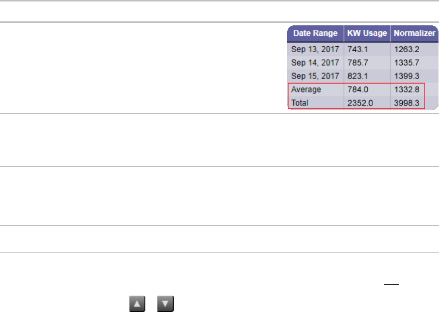
i-Vu Pro v7.0 Help CARRIER CORPORATION ©2020
All rights reserved
119
Options tab
1 Click the drop-down list to the left of the Add button, and select an option.
2 Click Add.
3 Select or enter information for the option you chose. See table below.
4 Click Accept or Apply.
Field
Notes
Show
Max/Min/Avg/Total
Check the appropriate boxes to show the
maximum value, minimum value, average, or
total at the bottom of the columns. Enter the
Column ID of the column that you want
labels to be in.
Show first ___rows
Enter the maximum number of rows to be displayed when the report is previewed or
run. This does not include the Max/Min/Avg/Total rows.
NOTE You can enter a value or variable name in this field. If you enter a variable, it
must be defined on the Variables tab.
Sort column
Sorts the specified column(s) from A to Z or 1 to ...
Example of comma separated list of column IDs:
date_range, kw_usage, normalizer
Check Reverse Sort to sort Z to A, ... to 1.
Filter rows
Select Include row when or Exclude row when a specified column (ID) equals a
specified value.
NOTE You can use multiple options for your report, but be aware that they will be processed in the order that
appear in the table at the top of the Options page. For example, if your first option is to Show the first 10 rows and
your second option is Filter rows, only the 10 rows will be filtered. To change the order of processing, select an
option in the table and then click or .
Output tab
On this tab, you can define the criteria for a report PDF or a chart on a graphic.
1 Select or enter information as needed. See table below.
2 Click Accept or Apply.

i-Vu Pro v7.0 Help CARRIER CORPORATION ©2020
All rights reserved
120
Field
Notes
PDF Output
Page orientation
Select Portrait or Landscape .
Page size
Select the page size that you want for a pdf.
Ignore page width
If the report exceeds the width of the selected Page size, select to ignore that width
and show all columns in the online PDF.
Font size
You can adjust the font size for the report's body.
Title font size
You can adjust the font size for the report's title.
Chart
These fields apply if you add a Chart control to a graphic in ViewBuilder. See To
produce a chart (page 130).
Axis label
For a Horizontal Bar Chart, this label will appear below the X axis.
For a Vertical Bar Chart or Line Chart, this label will appear to the left of the Y axis.
Data series
A column or row of numbers that are plotted in the chart.
Example:
For this report...
A horizontal bar chart will look like this...
By column

i-Vu Pro v7.0 Help CARRIER CORPORATION ©2020
All rights reserved
121
Field
Notes
By row
NOTE Pie charts show only one data series.
Show title
Show legend
Show chart border

i-Vu Pro v7.0 Help CARRIER CORPORATION ©2020
All rights reserved
122
Field
Notes
Graphics Refresh
A chart or data table control will refresh its report data every time you visit the
Graphics page or at the following refresh rates while the Graphics page is displayed.
If the report's primary column is...
Default refresh rate is...
A Date Range with a Frequency of Hourly or
Every 15 minutes
Every 5 minutes
Any other Date Range
0 (never refreshes)
Anything else
Every 30 seconds
Use custom refresh rate
Check this field to change the refresh rate. If your chart or data table shows a lot of
data, refreshing frequently could slow down your system. If most of the data is
historical data that does not change, you may want to set a longer refresh time.
Reset to defaults
Click Reset to return all fields on the Output tab to their original settings.
To preview a report
At the bottom of every tab in the Report Editor is a Preview section so that you can check your work. Click Show to
see the report. If you make changes to the report, click Refresh to update the preview.
You have the following options when previewing the report:
Show all columns
Includes columns defined as hidden and a column with additional
information about the Primary column.
Show Column ID
Each column header shows the display name and column ID.
Show Debug Information
Gives information for troubleshooting a report.
NOTES
If the preview shows Error, hover your cursor over the word to see a description of the error.
If the preview shows ?, this indicates there is no data.
To run a custom report
1 Select an item on the navigation tree where the report you want to run is accessible.
2 Click the Reports button drop-down arrow, and then select the report.
3 Optional: If the report was designed with variables (page 117), you can change the variables' values at the
top of the page.
NOTE Click Reset if you want to change the variables back to the value that was assigned when the report
was created.
4 Click Run.

i-Vu Pro v7.0 Help CARRIER CORPORATION ©2020
All rights reserved
123
NOTES
A ? in the report indicates there is no data.
Click Edit to change the report's design. See Creating a custom report (page 103) for field descriptions.
Click Schedule to schedule the report to run on a recurring basis. See Scheduling reports (page 140).
To edit or delete a custom report
1 Click the Reports button drop-down arrow, and then select Report Manager.
TIP Click on the Display Name or ID heading to sort the column.
2 Select the report, and then do one of the following:
○ Click Edit to open the Report Editor, make changes as needed, then click Accept. See Creating a custom
report (page 103) for field descriptions.
NOTE You can also double-click a report to open it in the Report Editor.
○ Click Delete, then click OK.
To export or import a custom report
You can export one or more reports from one system, copy them to another system, and then import the reports
into the i-Vu® Pro interface.
To export reports
1 Click the Reports drop-down arrow, and then select Report Manager.
2 Click Export.
3 Select the checkbox(es) for the report(s) that you want to export, or check Select All.
4 Click Export.
NOTE A single report is exported as a .table file. Multiple reports are exported as a .zip file.
TIP In the Report Manager or Export Report window, you can click on the Display Name or ID heading to sort
the column.
To import reports
1 Copy the .table or .zip file to the computer where you are importing them.
2 In the i-Vu® Pro interface, click the Reports drop-down arrow, and then select Report Manager.
3 Click Import.
4 Browse to the file that you are importing.

i-Vu Pro v7.0 Help CARRIER CORPORATION ©2020
All rights reserved
124
5 If a report ID that you are importing matches an existing report ID, select how you want to handle the situation:
Rename
Rename the report that you are importing.
Replace
Replace the existing report with the report you are importing.
Skip
Do not import the report with the duplicate name.
6 Click Import.
To organize custom reports by category
When you create a custom report, you can assign it to a category so that the report appears in the category in the
Reports button drop-down list.
To create a report category
1 In System Options, click to the left of the Categories folder, then click Report.
2 Click Add.
3 Type the Category Name and Reference Name.
4 Select a privilege so that only operators with that privilege can access reports in the category.
5 Click Accept.
NOTES
To edit a category, select the category, make your changes, then click Accept.
To delete a category, select the category, click Delete, then click Accept.

i-Vu Pro v7.0 Help CARRIER CORPORATION ©2020
All rights reserved
125
Using a custom report as the source for a Graphics page
A i-Vu® Pro custom report can be the data source for the following items on a Graphics page:
A data table
A value
A chart
A color map
For example, this report...
...supplies data to the chart and data table on this graphic
To produce a data table
To produce a data table like the example below, first create the report in the i-Vu® Pro interface and then create
the corresponding graphic in ViewBuilder.

i-Vu Pro v7.0 Help CARRIER CORPORATION ©2020
All rights reserved
126
To create the report in the i-Vu® Pro interface
Instructions
Example
1. Click the Reports drop-down
arrow, and then select Report
Manager.
2. Click Add.
3. On the Report Editor's Type tab,
type a Display name and ID for
the report.
4. In the Primary column field, select
the type of information that you want
the report to be based on (Control
Programs in this example).
5. On the Type tab (page 103), enter the
criteria
for the option that you selected in
step 4.
6. In the Primary column header field,
enter the heading that you want for
that column (Equipment in this
example).
7. Define each column in the report on
the Columns tab (page 106). See the
examples
on the right.
8. Define any other information you may
want, and then click Accept.

i-Vu Pro v7.0 Help CARRIER CORPORATION ©2020
All rights reserved
127
Instructions
Example

i-Vu Pro v7.0 Help CARRIER CORPORATION ©2020
All rights reserved
128
To create the graphic in ViewBuilder
Instructions
Example
1. Select File > New > Graphic, and
then click OK.
2. Click the Add Control tab
in the Tools window.
3. Click the Data Table control and then
click in the workspace.
4. In the Properties window, enter the
Report ID exactly as it appears in
the i-Vu® Pro Report Editor.
5. Resize the control so that it is at least
the size that the table will be in the
i-Vu® Pro interface. To resize,
enter a specific size in the Properties
window or drag the handles on the
control.
NOTE If the table is cut off when you
view the graphic in the i-Vu® Pro
interface, increase the size of the
data table control in ViewBuilder.
6. If you defined variables in the Report
Editor and you want to use a different
default value for the Data Table,
click in the Properties window,
type the variable's ID (from the
Report Editor), and then type the
new default value.
NOTE To have the data table show data for a
location other than the graphic's location, add
a variable and type location in the ID
column. Type the path to the location in the
Value column.
7. Save the graphic.

i-Vu Pro v7.0 Help CARRIER CORPORATION ©2020
All rights reserved
129
To reference a value in a data table
To reference the value of a cell in a data table, use one of these expressions:
CELL::table ID,column ID,column ID=value
CELL::table ID,column ID,numerical position in the column
NOTE The numerical position in the column can be positive if counting for the top or negative if coming from the
bottom.
Examples
To reference the value of 17.02 in the table below called "sample_table", below are a few ways you can reference
the value:
CELL::sample_table,c1,location=#e8
CELL::sample_table,c1,ref=#e8
CELL::sample_table,c1,3
CELL::sample_table,c1,-5

i-Vu Pro v7.0 Help CARRIER CORPORATION ©2020
All rights reserved
130
To produce a chart
To produce a bar chart like the example below, first create the report in the i-Vu® Pro interface and then create the
corresponding graphic in ViewBuilder.
NOTE When a chart that is based on a report is displayed on a Graphics page, you can hover over various points
on the chart to see values. You can also click on each item in the legend to turn that information on and off. See
Using a custom report as the source for a Graphics page (page 125) for more information on a chart.

i-Vu Pro v7.0 Help CARRIER CORPORATION ©2020
All rights reserved
131
To create the report in the i-Vu® Pro interface
Instructions
Example
1. Click the Reports drop-down
arrow, and then select Report
Manager.
2. Click Add.
3. On the Report Editor's Type tab,
type a Display name and ID for
the report.
4. In the Primary column field, select
the type of information that you want
to report based on (Date Range in
this example).
5. On the Type tab (page 103), enter the
criteria
for the option that you selected in
step 4.
6. In the Primary column header field,
enter the heading that you want for
that column (Date Range in this
example).

i-Vu Pro v7.0 Help CARRIER CORPORATION ©2020
All rights reserved
132
Instructions
Example
7. Define each column in the report on
the Columns tab (page 106).
NOTE In the example to the right, all
four columns have the same criteria.
8. Define the Chart options on the
Output tab (page 119).
9. Define any other information you may
want, and then click Accept.

i-Vu Pro v7.0 Help CARRIER CORPORATION ©2020
All rights reserved
133
To create the graphic in ViewBuilder
Instructions
Example
1. Select File > New > Graphic, and
then click OK.
2. Click the Add Control tab
in the Tools window.
3. Click the Chart control and then
click in the workspace.
4. In the Properties window, enter the
Report ID exactly as it appears in
the i-Vu® Pro Report Editor.
5. Select the Type of chart you want.
6. Resize the control so that it is at least
the size that the chart will be in the
i-Vu® Pro interface. To resize,
enter a specific size in the Properties
window or drag the handles on the
control.
NOTE If the chart is cut off when you
view the graphic in the i-Vu® Pro
interface, increase the size of the
chart control in ViewBuilder.
7. If you defined variables in the Report
Editor and you want to use a different
default value for the chart,
click in the Properties window,
type the variable's ID (from the
Report Editor), and then type the
new default value.
NOTE To have the chart show data for a
location other than the graphic's location, add
a variable and type location in the ID
column. Type the path to the location in the
Value column.
8. Save the graphic.

i-Vu Pro v7.0 Help CARRIER CORPORATION ©2020
All rights reserved
134
To produce a color map
A Graphics page color map shows specified colors for various conditions that are defined in an i-Vu® Pro report.
For example, a floorplan could show the percentage of time each zone is occupied. See image below. NOTE For
this type of color map, the control program must have a means of trending occupancy.
A color map can also have an option that lets a user switch between different kinds of information. For example, in
the image below, a user could click on the MTD kWh drop-down list and select YTD kWh.
To produce a color map:
1 Create the graphic in ViewBuilder.
2 Create the corresponding report in the i-Vu® Pro interface.
3 Edit the graphic to add information specific to the i-Vu® Pro report.
See instructions below.

i-Vu Pro v7.0 Help CARRIER CORPORATION ©2020
All rights reserved
135
Create the graphic in ViewBuilder
Instructions
Example
1. Add an image (floorplan, campus
map, etc.) to the graphic, and then
double-click the image to open the
Associations window.
2. Associate each item on your
image (zone, building, etc.). See
"Associating zones on a floorplan
to equipment" in ViewBuilder
Help.
NOTE The Variable Color
checkbox in the Associations
window must be checked.
3. Click Save and Close.
Create the report in the i-Vu® Pro interface
Instructions
Example
1. Click the Reports drop-down
arrow, and then select Report
Manager.
2. Click Add.
3. On the Report Editor's Type tab,
type a Display name and ID for
the report.
4. Uncheck Show in Reports menu.
5. In the Primary column field,
select Color Map.

i-Vu Pro v7.0 Help CARRIER CORPORATION ©2020
All rights reserved
136
Instructions
Example
6. Type a location in your system so that
you can preview the report
(#floor_1 in the example). This
location is only for testing your
entries in the Report Editor.
Associations to actual locations in the
system will be made in ViewBuilder.
NOTE You can add more than one
location if you want to see more in
the preview.
7. Click Add.
8. Optional: Select Include equipment
color column if you want to
automatically include a column for
i-Vu® Pro equipment
colors.
NOTE You can see this column in the
Preview section if you check Show
all columns.
8. Define each column in the report on
the Columns tab (page 106). See examples
of the
first two columns on the right.

i-Vu Pro v7.0 Help CARRIER CORPORATION ©2020
All rights reserved
137
Instructions
Example
A color map can retrieve color
information only from a column
that has the Render data as field
set to Color.
9. Define any other information
needed on the Report Editor tabs,
and then click Accept.

i-Vu Pro v7.0 Help CARRIER CORPORATION ©2020
All rights reserved
138
Edit the graphic in ViewBuilder to add report information
Instructions
Example
Follow steps 1 through 5 if the colormap
will show information from more than
one report column. If not, skip to step 6.
1. Select Configure > View
Properties.
2. On the Local Variables tab, click
.
3. Double-click Boolean in the Type
column, and then select Report
column in the drop-down list.
4. Double-click variable in the Name
column, and then replace
variable with colormap_column.
NOTE If the Graphic has multiple
images that will pull data from
different reports, add one variable
called colormap_column1, another
called colormap_column2, etc.
5. Click OK.
6. Double-click the image to open the
Associations window.
7. Click , and then enter the
following information:
• Report ID: Get the report ID
from the i-Vu® Pro
Report Editor.
• Default Column ID: This is
the column whose color is
displayed when the graphic
first appears. Get the Column
ID from the i-Vu® Pro
Report Editor. Leave blank if
the graphic will pull data from
only one report column.
• Column Name Local
Variable: Type the name of
the variable that you created in
step 5 above. Leave blank if
the graphic will pull data from
only one report column.
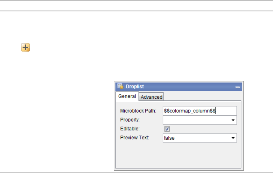
i-Vu Pro v7.0 Help CARRIER CORPORATION ©2020
All rights reserved
139
Instructions
Example
8. If a report uses a variable and
you want the colormap to use
a different default value than
what is defined in the
i-Vu® Pro Report Editor,
click in the Report
Properties window, type the
variable's ID (defined in the
Report Editor), and then type the
new default value.
9. If the colormap will show
information from more than one
report column, add a control
(droplist or radio buttons) that will
allow the user to select the
information they want to see.
10. In the Microblock Path field,
enter the local variable that you
defined in step 4, enclosing it in
$$.
11. Finish the graphic and then test it
in the i-Vu® Pro interface.
Troubleshooting custom reports
If a Graphics page contains a chart, data table, or color map that is retrieving information from a very large
report, the graphic may be slow to load or refresh. You can do the following to improve this condition:
○ Verify that your system follows the recommendations in i-Vu® Pro v7.0 client, server, operating system,
and database requirements.
○ Reduce the size of the report by redefining the primary column criteria on the Report Editor's Type tab.
○ Filter the report to show only a portion of the information. You can filter the report on the Report Editor's
Options tab.
○ Increase the refresh time (default is 30 seconds). If the chart, data table, or color map is based on
information that changes infrequently, increase the refresh rate or set it to 0 to turn off refreshing. You
can adjust the refresh rate on the Report Editor's Options tab.
○ Reduce the number of controls on the graphic that are pulling data from different reports.
If an Invalid Report Definitions section appears at the bottom of the Report Manager page, one of the
following has occurred:
○ The report's file or file name has been manually manipulated, invalidating the report's digital signature.
Contact Technical Support to resolve this problem.
○ The report is set up to have an add-on supply content for the report, but the add-on has not been
installed in the i-Vu® Pro interface. Install the add-on to resolve this problem.

i-Vu Pro v7.0 Help CARRIER CORPORATION ©2020
All rights reserved
140
To create a PDF, XLS, or CSV file
These reports...
Can be output as...
Notes
v7.0 custom reports
A PDF file
A CSV file
Preconfigured reports and
v6.5 and earlier custom reports
A PDF file
An XLS file
A CSV file
For a v6.5 and earlier CVS file, you must
enable Support CSV text format on the
Reports > Options tab before you run the
report.
To output a file:
1 Run a report.
2 Click PDF, XLS, or CSV to download the file.
NOTE To create a CSV file when using Safari, see instructions below.
To create a CSV file when using Safari
1 Run a report.
2 Click CSV. A pop-up displays the results.
3 Select File > Save As.
4 In the Format field, select Page Source.
5 Add the .csv extension to the file name.
6 Select the save location in the Where field.
7 Click Save.
8 Close the popup.
NOTE If you need a digitally signed PDF to comply with 21 CFR Part 11, open the PDF in a program that supports
digital signing such as the Adobe® Acrobat® application, then sign the PDF. The i-Vu® Pro application does not
support digital signing because 21 CFR Part 11 requires that the signature be added manually, not through an
automated process.
Scheduling reports
You can schedule a report so that it runs on a recurring basis. The report is saved as a file (PDF, CSV, or XLS), and
you can choose to have it automatically emailed to someone.
NOTE You can also use the following alarm actions to run a report:
The Send E-mail alarm action (page 78) can run any i-Vu® Pro report and attach it to the email.
The Write to File alarm action (page 87) can run any i-Vu® Pro report and save it as a file.
For both alarm actions, the report can be a PDF, HTML, XLS, or CSV file.

i-Vu Pro v7.0 Help CARRIER CORPORATION ©2020
All rights reserved
141
To schedule a report
1 Click the Reports drop-down arrow, and then select the report that you want to schedule.
2 Click the Schedule button.
3 Enter the information in each field.
Fields
Notes
Description
Enter a brief description of the report or how this schedule will be used.
Operator
The report will be run based on the selected operator's privileges.
Run report
Define when the report will run by selecting options in the drop-down lists.
At __:__ __
Enter the time of day that you want the report to run.
Save report as
v7.0 reports can be output as a PDF or CSV file. Preconfigured reports and v6.5
reports can also be output as an XLS file. Select the type of report file that you
want.
NOTE See Output tab (page 119) for a description of the PDF options that are
available in the Report Editor.
Keep latest
Enter the number of files and Schedule History entries that you want to keep for
this report. As a new file or entry is saved, the oldest one is deleted.
Email report
Enter the information needed to email the report each time it runs.
NOTE For the i-Vu® Pro application to email a report, you must define the Email
Server configuration on the System Settings > General tab (page 274).
4 Click Accept.
NOTE The following reports have additional scheduling options available. Scheduling these reports without
configuring schedule options results in an error; see View History in To manage scheduled reports (page 142).
Alarms > Alarms
Security > Location Audit Log
Security > System Audit Log
See To configure scheduled Alarms and Security Reports (page 101).

i-Vu Pro v7.0 Help CARRIER CORPORATION ©2020
All rights reserved
142
To manage scheduled reports
Click the Reports drop-down arrow, and then select Scheduled Reports. The table shows any report that was
scheduled on the report's page.*
Select a schedule
and then click...
To...
Edit
Change the report's schedule in the Schedule Editor.
NOTE You can also double-click a schedule in the table to open the Schedule Editor.
View History
See when the report ran. Click PDF, CSV, or XLS in the Results column to download
the report that was produced.
NOTE The XLS option is not available for v7.0 custom reports.
Delete
Remove the schedule. This removes its history and all associated files.
* You can also access this table by going to System Options and selecting Scheduled Reports.
If a report fails
The table below will show a red X and a system alarm will be generated.
Select the schedule in the table above, and then click View History. Hold the cursor over the word Failure to see
hover text describing what failed.

i-Vu Pro v7.0 Help CARRIER CORPORATION ©2020
All rights reserved
143
Working with legacy (v6.5 and earlier) custom reports
Although i-Vu® Pro v7.0 has a new method of creating and managing reports, you can still create or edit the
following reports that were available in i-Vu® Pro v6.5 and earlier systems. These reports will be accessible from
the Reports button drop-down list, but not the Report Manager.
This report...
allows you to...
Equipment Summary
View the following information for equipment at or below the location where the
report was created:
Color
Active alarm
Locked values
Current value of selected points
Combined schedule
See To create an Equipment Summary report (page 143).
Equipment Values
Compare point information. See To create an Equipment Values report (page
144).
Trend Samples
View trend values for a particular time frame. See To create an Trend Samples
report (page 146).
NOTE You can schedule a report to run on a recurring basis. See Scheduling reports (page 140).
To create an Equipment Summary report
An Equipment Summary report can provide the following information for equipment at or below the location where
the report is created.
Color
Active alarm
Locked values
Current value of selected points
Combined schedule
To create an Equipment Summary report:
1 On the navigation tree, select the location where you want to view the report.
2 Click the Reports button drop-down arrow, then select Add Legacy Report.
3 Select Equipment Summary.
4 Optional: Select a Category.
NOTE The Category field is visible only if you have defined report categories. See To organize custom reports
(page 124).
5 Type a name for the report.

i-Vu Pro v7.0 Help CARRIER CORPORATION ©2020
All rights reserved
144
6 Click Create.
7 Define the Title, Page Size and orientation, and the Maximum number of rows.
8 Check or uncheck the Optional Sections checkboxes as needed.
9 Optional: Check Include only specific control programs at or below this location, then type the names of the
control programs.
10 Select Available Points that you want to include in the report. Use Ctrl+click, Shift+click, or both to select
multiple items.
11 Click Add.
12 Click Accept.
13 Click Run.
NOTE To run this report later, go to the location where the report was created. Click the Reports button drop-down
arrow, select the report, then click Run.
To create an Equipment Values report
mAn Equipment Values report allows you to compare point information.
To create an Equipment Values report:
1 On the navigation tree, select the location where you want to view the report.
2 Click the Reports button drop-down arrow, then select Add Legacy Report.
3 Select Equipment Values.
4 Optional: Select a Category.
NOTE The Category drop-down list is only visible if you have defined report categories. See To organize
custom reports (page 124).
5 Type a name for the report.
6 Click Create.
7 On the tree in the Rows section, select the pieces of equipment you want to view in the report. (Use Ctrl+click,
Shift+click, or both to select multiple items.) Then click Add.
8 Optional: Check Highlight alternate rows to make the report easier to analyze.
9 Click Next or next to Columns.
10 Verify or change the report Title, Page units of measure for defining column widths, and Outer border
characteristics.
11 Select a column in the report preview.
NOTE The selected column is light blue.
12 Under Column Header, define how you want the column header to look.
13 Under Column Data, define the data you want in the column and how you want it to look. See table below.
NOTE Select General from the Format drop-down list unless you want to define the number of places to the
right of the decimal point for the displayed value.
14 Optional: Use the Add, Delete, and arrow buttons below the report preview to manipulate the columns.

i-Vu Pro v7.0 Help CARRIER CORPORATION ©2020
All rights reserved
145
15 Optional: Click next to Page to change the page size and orientation.
NOTE Changing the size and orientation of the printed page also changes the report layout on the View tab.
16 Click Accept.
17 Click Run.
NOTE To run this report later, go to the location where the report was created. Click the Reports button drop-down
arrow, select the report, then click Run.
Type of Column Data
Point
Displays point data in the column.
Display
Select the property to show in this column.
Data is named
differently in some
control programs
Select this checkbox if similar points have different names in
different control programs. Then add each of the names to the
Name to use list.
For example, if a point is named Zone Temp in one control
program and Zone Temperature in different control program, add
both names to the list.
Point to use
Select the name of the point to show in the column.
Trend Sample
Display
Select First, Minimum, Maximum, or Last recorded trend value.
Data is named
differently in some
control programs
Select this checkbox if similar points have different names in
different control programs. Then add each of the names to the
Name to use list.
For example, if a point is named Zone Temp in one control
program and Zone Temperature in different control program, add
both names to the list.
Trend to use
Select the name of the point to show in the column.
Set
Click to have all columns in the report use the same time range.
Time Range
Select the time range to run the report for.
Trend Calculation
Display
Select the type of calculation to show in the column, Average or
Total.
Data is named
differently in some
control programs
Select this checkbox if similar points have different names in
different control programs. Then add each of the names to the
Name to use list.
For example, if a point is named Zone Temp in one control
program and Zone Temperature in different control program, add
both names to the list.
Trend to use
Select the name of the point to show in the column.

i-Vu Pro v7.0 Help CARRIER CORPORATION ©2020
All rights reserved
146
Type of Column Data
Set
Click to have all columns in the report use the same time range.
Time Range
Select the time range to run the report for.
Control Program
Display
Select Color, Display Name, Display Path, Notes, Prime Variable,
or Reference Name to show in the column.
Expression
Data is named
differently in some
control programs
Select this checkbox if similar points have different names in
different control programs. Then add each of the names to the
Name to use list.
For example, if a point is named Zone Temp in one control
program and Zone Temperature in different control program, add
both names to the list.
Expression
Type the path relative to the current control program. The path
must return a string value. See Defining i-Vu® Pro paths (page
175) for more information on paths.
To display the Notes on an equipment's Properties page, type
.notations in this field.
To create a Trend Samples report
A Trend Samples report provides trend values for a particular time frame.
To create a Trend Samples report:
1 On the navigation tree, select the location where you want to view the report.
2 Select the Reports button drop-down arrow, then select Add Legacy Report.
3 Select Trend Samples.
4 Optional: Select a Category.
NOTE The Category drop-down list is only visible if you have defined report categories. See To organize
custom reports (page 124).
5 Type a name for the report.
6 Click Create.
7 Select a Time Range from the drop-down list, then refine that option by selecting an option from the drop-
down list(s) to the right.
8 Define the trend data.
NOTES
○ Calculate values for missing samples calculates a value based on the 2 closest values to the time
interval.
○ Find the closest sample displays the value closest to the time interval selected.

i-Vu Pro v7.0 Help CARRIER CORPORATION ©2020
All rights reserved
147
9 Optional: Check Highlight alternate rows to make the report easier to analyze.
10 Click Next or next to Columns.
11 Verify or change the report Title, Page units of measure for defining column widths, and Outer border
characteristics.
12 Select a column in the report preview.
NOTE The selected column is light purple.
13 Under Column Header, define how you want the column header to look.
14 Under Column Data, select the source of the trend data and how you want the data to look.
NOTE Select General from the Format drop-down list unless you want to define the number of places to the
right of the decimal point for the displayed value.
15 Optional: Use the Add, Delete, and arrow buttons below the report preview to manipulate the columns.
16 Optional: Click next to Page to change the page size and orientation.
NOTE Changing the size and orientation of the printed page also changes the report layout on the View tab.
17 Click Accept.
18 Click Run.
NOTE To run this report later, go to the location where the report was created. Click the Reports button drop-down
arrow, select the report, then click Run.
To save a v6.5 or earlier custom report's design
You can save the design of an Equipment Values report or a Trend Samples report for reuse in another location. Or,
you can create a library of different report designs to pull from as needed.
To save a report's design
1 Create the Equipment Values (page 144) or Trend Samples (page 146) report.
2 On the Reports > Design tab, click the Save Report Design button.
NOTE The .reportdesign file includes the report name. If you save multiple report designs in your system, each
of those reports must have a unique name.
To use the report design at a different location in the system
1 Select the location in the navigation tree.
2 Select Reports > Add Legacy Report.
3 In step 1, select Report design, then select the report name in the drop-down list.
4 In step 2, type a report Name.
5 In step 3, click Create.
i-Vu Pro v7.0 Help CARRIER CORPORATION ©2020
All rights reserved
148
To edit or delete a v6.5 or earlier custom report
1 Select the item on the navigation tree where the report was created.
2 Click the Reports button drop-down arrow, then select the report you want to edit or delete.
3 Do one of the following on the Design tab:
○ Edit the report, then click Accept.
○ Click the Delete Report button, then click OK.

i-Vu Pro v7.0 Help CARRIER CORPORATION ©2020
All rights reserved
149
Privileges control which parts of the i-Vu® Pro system an operator can access. Privileges also control what an
operator can do and what he can change.
To set up operator access to your system:
1 Log in to the i-Vu® Pro application as the Administrator. See Operators and operator groups (page 153).
2 Define privilege sets by job function. See Privilege sets (page 149).
3 Enter each operator in the system by assigning him privilege sets and entering settings that apply only to him.
If you need to assign the same privilege set to multiple operators, you can create an operator group and
assign the privilege set to the group. See Operators and operator groups (page 153).
An operator can change many of his operator settings on the My Settings page (page 273).
To access the i-Vu® Pro interface, an operator must enter his user name and password. You can change the rules
for passwords in the advanced password policy (page 162).
Restricting operator access
To restrict access to your system, you can:
Restrict an operator's privileges
Use location-dependent operator access (page 157)
Change a microblock's Editing Privilege from Preset to a specific privilege. The microblock's properties will be
editable only by an operator that has that privilege.
CAUTION Each microblock property has a default Editing Privilege (represented by the Preset option)
that is appropriate for that property. Changing Preset to a specific privilege changes every property in the
microblock to the same privilege which may produce undesirable results.
Privilege sets
A privilege set is a group of one or more privileges (page 150). The Administrator creates privilege sets and assigns
them to operators and operator groups.
Operator access

i-Vu Pro v7.0 Help CARRIER CORPORATION ©2020
All rights reserved
150
Privileges
This privilege...
allows an operator to...
Installer
Add, edit, and delete operators, operator groups, and privilege
sets.
Update the i-Vu® Pro system with service packs and patches.
Register the i-Vu® Pro software.
Enable and set up advanced security features such as location-
dependent operator access (page 157) and the advanced
password policy (page 162).
Add and remove i-Vu® Pro add-ons.
This Access privilege...
allows an operator to access (but not edit)...
Access System Tree
the Installer view pages.
Access Control Program Items
tables in the navigation tree or Properties pages.
Access Scheduling Groups
pages in the User view navigation tree for Schedule Groups.
Access System Options Items
under > System Options.
Access Alarms
alarms.
Access Logic Pages
Logic pages.
This Parameter privilege...
allows an operator to edit properties such as...
Edit Setpoint Parameters
occupied and unoccupied heating and cooling setpoints.
Edit Setpoint Tuning Parameters
demand level setpoint offsets, color band offsets, heating and cooling
capacities and design temperatures, color hysteresis, and learning
adaptive optimal start capacity adjustment values.
Edit Tuning Parameters
gains, limits, trip points, hysteresis, color bandwidths, design
temperatures, and optimal start/stop.
Edit Manual Override Parameters
locks on input, output, and network points.
Edit Point Setup Parameters
point number, type, range, and network source and destination.
Edit Restricted Parameters
properties the installer restricted with this privilege.
Edit Category Assignments
Alarm, Graphic, Trend, and Report category assignments.
Edit History Value Reset
elapsed active time and history resets, and runtime hours.

i-Vu Pro v7.0 Help CARRIER CORPORATION ©2020
All rights reserved
151
This Parameter privilege...
allows an operator to edit properties such as...
Edit Trend Parameters
enable trend logging, log intervals, and log start/stop times.
Edit Calibration Parameters
point calibration offsets.
Edit Hardware Controller Parameters
module driver properties.
Edit Critical Configuration
critical properties the installer protected with this privilege.
Edit Area Name
area display names.
Edit Control Program Name
equipment display names.
Edit Alarm Configuration
enabling/disabling alarms and editing alarm messages, actions,
categories, and templates.
Edit Status Display Tables
tables available under Status.
Edit Maintenance Tables
tables available under Maintenance.
Edit User Config Tables
tables available under User Config.
Edit Service Config Tables
tables available under Service Config.
Edit Setpoint Tables
tables available under Setpoint.
Edit Time Schedule data Tables
tables available under Time Schedule.
This Functional privilege...
allows an operator to...
Manage Alarm Messages
and Actions
add, edit, and delete alarm messages and actions.
Maintain System Parameters
edit all properties on the System Options pages.
Maintain Schedules
add, edit, delete, and download schedules.
Maintain Schedule Group Members
add, edit, and delete schedule groups.
Maintain Categories
add, edit, and delete categories.
Acknowledge Non-Critical Alarms
acknowledge all non-critical alarms.
Acknowledge Critical Alarms
acknowledge all critical alarms.
Force Normal Non-Critical Alarms
force non-critical alarms to return to normal.
Force Normal Critical Alarms
force critical alarms to return to normal.
Delete Non-Critical Alarms
delete non-critical alarms.
Delete Critical Alarms
delete critical alarms.
Execute Audit Log Report
run the Location Audit Log and System Audit Log reports.
Download Controllers
mark equipment for download and initiate a download.
System Shutdown
issue the Shutdown manual command that shuts down i-Vu® Pro
Server.

i-Vu Pro v7.0 Help CARRIER CORPORATION ©2020
All rights reserved
152
This Functional privilege...
allows an operator to...
Engineer System
log in and make database changes in SiteBuilder.
use the copy, notify, reload, and revert manual commands.
access the navigation tree right-click menus in i-Vu® Pro.
Add text in the Notes field on an equipment's Properties page.
Access Commissioning Tools
access:
Equipment Checkout
Airflow Configuration
Trend, Report, and Graphic categories that require this privilege
Discovery tool
Maintain Graphs and Reports
add, edit, and delete trend graphs and reports.
Maintain Connections
edit Connections page properties.
Remote File Management
access files using a WebDAV utility.
Remote Data Access-SOAP
retrieve i-Vu® Pro data through an Enterprise Data Exchange (SOAP)
application.
Do not audit changes made using
SOAP (Web services)
not have his SOAP (Web services) changes recorded in the Audit Log.
Manual Commands/Console
Operations
access the manual command dialog box and issue basic manual
commands.
Manual Commands/File IO
execute manual commands that access the server's file system.
Manual Commands/Adv Network
execute manual commands that directly access network
communications.
Manual Commands/Unrestricted
execute manual commands that bypass all safeguards and may
cause unpredictable results if used incorrectly.
Change My Settings
edit preferences on operator's My Settings page.
To create a custom privilege
You can assign a privilege to a Graphic, Property, Trend, or Report category so that only operators with that
privilege can access the category. You assign a category privilege on the page where you create or edit categories.
If all the other privileges are too widely used to accomplish the results you want, you can assign one of the five
Access User Category privileges to the operator(s) and category.
For example, your system has 2 graphics categories, HVAC and Lighting/Security. You want HVAC technicians to
see only the HVAC graphics and security personnel to see only the Lighting/Security graphics. To do this:
Assign...
To...
Results
Access User
Category 1
HVAC graphics category
and
HVAC technicians only
The security personnel cannot see the HVAC
graphics because they do not have Access User
Category 1.

i-Vu Pro v7.0 Help CARRIER CORPORATION ©2020
All rights reserved
153
Assign...
To...
Results
Access User
Category 2
Lighting/Security Graphics category
and
Security personnel only
The HVAC technicians cannot see the
Lighting/Security graphics because they do not
have Access User Category 2.
To add or edit a privilege set
1 On the System Options tree, select Privilege Sets.
2 Click Add to create a new privilege set, or select a privilege set to edit.
3 Type the Name and Reference Name for the privilege set.
4 Check each privilege (page 150) that you want to include in the privilege set.
5 Click Accept.
CAUTION Include all required access privileges in a privilege set. For example, if you add Acknowledge Non-
Critical Alarms to a privilege set, also add Access Alarms to that privilege set.
TIP (Location-independent security only) To create a privilege set that is similar to an existing set, select the
existing set, then click Add. The privileges that are initially selected are identical to those of the existing set.
To delete a privilege set
1 On the System Options tree, select Privilege Sets.
2 Select the privilege set to be deleted.
3 Click Delete.
4 Click OK.
5 Click Accept.
Operators and operator groups
When you create a new system in SiteBuilder, you assign a login name and password to the administrator operator.
This administrator operator sets up each operator in the i-Vu® Pro interface by entering the necessary settings and
assigning one or more privilege sets (page 149) to the operator.
NOTES
The Installer privilege set has more privileges than the Administrator privilege set and is necessary for
commissioning equipment.
For security purposes, do use Administrator or Installer as the actual Login Name.

i-Vu Pro v7.0 Help CARRIER CORPORATION ©2020
All rights reserved
154
Operator groups give you the ability to assign privilege sets to a group of operators instead of the individual
operators. Operator groups are useful if you have multiple operators who need the same privilege set or you have
positions with high turnover rates. You can assign an operator to a group when you enter the operator or when you
create the operator group.
CAUTION Passwords can be forgotten. To ensure access to the i-Vu® Pro administrative functions, assign the
Installer or Administrator privilege set to at least 2 operators.
To add or edit an operator
1 On the System Options tree, select Operators.
2 Click Add to enter a new operator, or select an operator to edit his settings.
3 Enter information on this page as needed. See table below.
4 Click Accept.
Field
Notes
Login Name
The name the operator must type to log in to the system. This name must be unique
within the system.
Change password
Enable this field, then type the current and new password and then confirm. Limit is
minimum of 8 and maximum 40 characters of any type.
NOTE An operator can change his password on the My Settings page (page 273),
unless they have the Guest System-wide Privilege Set.
Force User to Change
Password at login?
Forces the operator to change his password immediately after his next login.
NOTE Use this field with the Change Password field to create a temporary password
that the operator must change after his next login.
Exempt From
Password Policy
If Use advanced password policy is enabled on the System Settings > Security tab
(page 279), select this option if you do not want the policy to apply to this operator.
Logoff options
If Log off operators after __ of inactivity is enabled on the System Settings > Security
tab (page 279), select one of the 3 logoff options.
Personal Information
You can enter contact information for this operator.
NOTE An operator can enter contact information on the My Settings page (page 273).
Starting Location and
Starting Page
The i-Vu® Pro location and page that will be displayed after the operator logs in.

i-Vu Pro v7.0 Help CARRIER CORPORATION ©2020
All rights reserved
155
Field
Notes
System-wide Privilege
Sets
Select the privilege set(s) that you want to assign to the operator. The Effective
System-wide Privileges list show which privileges the operator will have.
NOTES
Click Show current privileges only to see only the selected privilege sets and
privileges.
A grayed out privilege set with a group name beside it indicates the operator is
inheriting that privilege set from the group.
TIP To test the settings and privileges that you gave to an operator, you can open a second browser session
on your computer and log in as the operator. For instructions on opening a second session in the browser you are
using, see Setting up i-Vu® Pro client devices and web browsers (page 267).
To delete an operator
1 On the System Options tree, select Operators.
2 Select the operator.
3 Click Delete.
4 Click Accept.
To add or edit an operator group
1 On the System Options tree, select Operator Groups.
2 Click Add to create a new operator group, or select an operator group to edit it.
3 Type the Display Name and Reference Name for the operator group.
4 Under Members, select the operators and/or groups that you want to add to the new group.
5 Under Privilege Sets, select the privilege sets (page 149) that you want to assign to the new group.
NOTE To see what privileges are included in a privilege set, go to the Privilege Sets page and then select the
privilege set in the table.
6 Click Accept.
TIP Every operator is automatically a member of a permanent default group called Everybody. You can assign
privilege sets to this group.

i-Vu Pro v7.0 Help CARRIER CORPORATION ©2020
All rights reserved
156
To delete an operator group
1 On the System Options tree, select Operator Groups.
2 Select the operator group.
3 Click Delete.
4 Click Accept.
CAUTION When you delete an operator group, its individual members lose the privilege sets that were
assigned to the group.
To change My Settings
On the My Settings page, you can change settings, such as your:
Password
Viewing preferences
Contact information
NOTE The System Administrator can also change these settings on the Operators page.
To change your settings:
1 Click > System Options > My Settings.
2 Make changes on the Settings or Contact Info tab. See table below.
3 Click Accept.
Field
Notes
Change password
Enable this field, then type your current and new password and then confirm.
Limit is minimum of 8 and maximum 40 characters of any type.
Starting Location and
Starting Page
The i-Vu® Pro location and page that will be displayed after you log in.
NOTE You must click Apply first if you have entered any other changes.
Language
The language and formatting conventions you want to see in the i-Vu® Pro
interface.
NOTES
If you will be using a language other than English, see Setting up your
system for non-English languages (page 297) for additional requirements.
If support for your selected language is removed in SiteBuilder, the i-Vu®
Pro application will automatically assign the System language to you.

i-Vu Pro v7.0 Help CARRIER CORPORATION ©2020
All rights reserved
157
Automatically collapse trees
Expands only one tree branch at a time.
Automatically download
schedules on each change
Select to automatically download all new schedules that you create and
schedules that you change.
Play sound at browser when
server receives
Check Non-critical alarms or Critical alarms if you want the system to audibly
notify you when that type of alarm is received.
You can specify a different sound file.
• Internet Explorer®, Firefox®, and Safari® support .wav, .mp3, or .au files.
• Google
TM
Chrome
TM
supports .wav or .mp3 files.
1 Put your file in the webroot\_common\lvl5\sounds folder.
2 In the Sound File field, replace normal_alarm.wav or critical_alarm.wav with
the name of your sound file.
NOTE You can put your sound file anywhere under the i-Vu_Pro_x.x folder, but
you must change the path in the Sound File field.
Advanced security
Location-dependent operator access
You can set up operator access to your system to be location-dependent. This type of operator access lets you
assign privileges to an operator only at locations in the system where he needs them. For example, you could
assign an operator mechanic privileges in one building in a system, view-only privileges in another building, and no
privileges in a third building.
i-Vu® Pro systems default to location-independent operator access in which an operator’s privileges apply
throughout the system. You should understand this type of operator access before switching to location-
dependent. See Operator access (page 149) for more information on location-independent operator access.
To switch to location-dependent access
CAUTIONS
Create a backup of your system before you begin. Switching to location-dependent operator access changes
the configuration of operators and privilege sets. If you need to revert to location-independent operator
access, your previous configuration cannot be automatically restored.
If you change the policy after you create and assign privilege sets to operators, you may need to reconfigure
your operators’ privileges.
To switch to location-dependent operator access:
1 On the System Options tree, select System Settings.
2 On the Security tab under Security Policy, click Change Policy.
3 Follow the on-screen instructions.

i-Vu Pro v7.0 Help CARRIER CORPORATION ©2020
All rights reserved
158
System-wide privileges and privilege sets
When using location-dependent operator access, privileges are either system-wide or local.
System-wide privileges allow an operator to perform functions throughout the entire system, such as performing a
system shutdown.
You assign System-wide Privilege Sets to system-wide privilege sets and local privileges to local privilege sets. Use
the following table in planning which privileges to assign to a privilege set. For a description of each privilege, see
Privileges (page 150).
Check Show current privileges only.
System-wide Privilege Sets
Effective System-wide Privileges
Administrator
Guest
Installer
Power User
Standard User
Access privileges
Access System Tree
Access Control Program Items
Access Scheduling Groups
Access System Options Items
Access Alarms
Access Logic Pages
Functional Privileges
Manage Alarm Messages and Actions
Maintain System Parameters
Maintain Schedules
Maintain Schedule Group Members
Maintain Categories
Acknowledge Non-Critical Alarms
Acknowledge Critical Alarms
Force Normal Non-Critical Alarms
Force Normal Critical Alarms
Delete Non-Critical Alarms
Delete Critical Alarms
Execute Audit Log Report
Download Controllers
System Shutdown
Engineer System
Access Commissioning Tools
Maintain Graphs and Reports
Maintain Connections
Remote File Management
Remote Data Access-SOAP
Do not audit changes made using SOAP
Manual Commands/Console Operations
Manual Commands/File IO
Manual Commands/Adv Network
Manual Commands/Unrestricted
Change My Settings

i-Vu Pro v7.0 Help CARRIER CORPORATION ©2020
All rights reserved
159
System-wide Privilege Sets
Effective System-wide Privileges
Parameter Privileges
Edit Setpoint Parameters
Edit Setpoint Tuning Parameters
Edit Tuning Parameters
Edit Manual Override Parameters
Edit Point Setup Parameters
Edit Restricted Parameters
Edit Category Assignments
Edit History Value Reset
Edit Trend Parameters
Edit Calibration Parameters
Edit Hardware Controller Parameters
Edit Area Name
Edit Control Program Name
Edit Alarm Configuration
Edit Status Display Tables
Edit Maintenance Tables
Edit User Config Tables
Edit Service Config Tables
Edit Setpoint Tables
Edit Time Schedule Data Tables
NOTES
For an operator to add, edit, or delete schedule groups, he must have the system-wide privilege Maintain
Schedule Group Members. He must also have the local privileges Access System Tree and Maintain
Schedules at each location that is a member of the schedule group.
If you switch to location-dependent operator access in a system that has operators and privileges set up, the i-
Vu® Pro application splits any existing privilege set containing local and system-wide privileges into 2
separate privilege sets - one local and one system-wide. Operators’ system-wide privilege sets still apply
throughout the system. The operators’ local privilege sets are automatically assigned at the system level. You
can then reassign the local privilege sets to the operators at the locations where they need them.
To add a privilege set
Adding a privilege set using location-dependent operator access is the same as using location-independent
operator access except that you must select whether you are adding a system-wide or local privilege set. See
Privilege sets (page 149).
i-Vu Pro v7.0 Help CARRIER CORPORATION ©2020
All rights reserved
160
To assign privilege sets to an operator
Assign a system-wide privilege set to an operator on the Operators page in the same way you would assign
privilege sets in a system using location-independent operator access. See Operators and Operator Groups (page
153).
Assign a local privilege set to an operator at locations on the navigation tree where he needs the privileges.
1 Select a location on the navigation tree.
2 Click Privileges.
3 On the Configure tab, click Add.
4 Select the operator or operator group.
5 Click OK.
6 Select the privilege set(s) that you want the operator to have.
7 Click Accept.
To delete a local privilege set assignment
1 On the navigation tree, select the location where the assignment was made.
2 Click Privileges.
3 Select the assignment under Privilege Set Assignments at this Level.
4 Click Delete.
5 Click Accept.
Restricting access in the system
Restricting an operator’s access to areas of the system
You can give an operator access to only a specific area of the system. All other areas will be either grayed out or
not visible when the operator logs in to the i-Vu® Pro interface.
EXAMPLE Assigning an operator the Access System Tree privilege for the Second Floor area only allows that
operator to see the Second Floor area and the controllers beneath that area. The First Floor or any other areas are
grayed out or not visible.

i-Vu Pro v7.0 Help CARRIER CORPORATION ©2020
All rights reserved
161
Restricted access
Full system access
Restricting all operator access to a location
To remove all operators’ local privileges from a location so that you can assign access only to a specific
operator(s), navigate to the location, select Privileges, then uncheck Inherit security privileges from above this
level.
Security Assignments Report
A Security Assignments Report shows an operator’s local and system-wide privileges and privilege sets at a specific
location.
1 Select the location on the navigation tree.
2 Click the Reports button drop-down arrow, then select Security > Security Assignments.
3 On the Options tab, select an operator.
4 Click Run.
Recording reasons for edits (21 CFR Part 11)
The i-Vu® Pro application provides support for 21 CFR Part 11. With this feature enabled, the i-Vu® Pro application
can require an operator to record a reason for changing an equipment property, or acknowledging an alarm, before
it accepts the change. The i-Vu® Pro Audit Log report then displays the operator's name and the recorded reason
for making the change.
To set up equipment to require reasons for changes
1 On the i-Vu® Pro navigation tree, right-click the equipment, then select Configure.
2 Check Require operator to record any changes to control program. (Audit logging must be enabled.)
NOTE In order to enable this feature to record changes, you must also enable Alarm requires
acknowledgment and/or Return requires acknowledgment on the Alarms > Enable/Disable tab.
3 Click Accept.
NOTE You can also turn this setting on in SiteBuilder in the equipment's properties dialog box.

i-Vu Pro v7.0 Help CARRIER CORPORATION ©2020
All rights reserved
162
To view reasons for changing equipment properties
1 On the i-Vu® Pro tree, select a piece of equipment that requires reasons for change.
2 Click the Reports button drop-down arrow, select Security > Location Audit Log or System Audit Log.
3 On the Options tab under Display the following columns, check Reason.
4 Click Run.
Advanced password policy
You can set up an i-Vu® Pro password policy to meet your security needs.
1 On the System Options tree, select System Settings.
2 On the Security tab under Operators, enter information in the fields described below.
NOTE See System Settings (page 274) for information on all the other fields.
Field
Notes
Use advanced password policy
Enable this field to put restrictions on passwords.
An operator’s login name and password must be different when this
policy is enabled.
After you change the password policy, any operator whose password
doesn't meet the new requirements will not be locked out of the system,
but will be prompted to create a new password.
Passwords must contain
You can specify how many characters and which of the following types of
characters a password must contain:
Numbers
Special characters—any keyboard character that is not a number or
letter.
Letters—uppercase, lowercase, or both.
Cannot be changed more than once
every __ days.
Enter a number to limit how often users can change their passwords.
When set to 0, users can change them as often as they want.
May not be reused until __ different
passwords are used.
Enter a number between 1 and 20. Enter 0 to reuse passwords without a
delay.
Expire after __ days
Enable to set the number of days an operator can use his password
before the system requires him to change it. Enter a number between 1
and 999.
Force expiration
Click this button to force every user's password to expire. Each user will
be prompted to change their password when they next attempt to log in
to the i-Vu® Pro interface.

i-Vu Pro v7.0 Help CARRIER CORPORATION ©2020
All rights reserved
163
To run a manual command:
1 Click and then select Manual Command.
2 Type the manual command in the dialog box, then click OK.
TIP Ctrl+Shift+M also opens the dialog box.
You must have the Installer or Admin role to access the manual commands dialog box. Some commands are
restricted to the Installer role only.
Command
Description
addon
Opens a dialog box where you can upload, start, stop, or remove an add-on
program.
autopilot location
In Internet Explorer® only–Displays the full path for the current location.
You can copy and paste the path into the autopilot.xml file that runs the i-
Vu® Pro autopilot. See Running the i-Vu® Pro autopilot (page 170).
bacnet bind show
Shows the selected device's current BACnet bindings.
bacnet bind clear
Clears the selected device's BACnet bindings so that they can be
rediscovered.
bacnet showindex
Displays all files (file name, size, date) downloaded to the selected
controller.
bbmd commands:
You must have the Installer Role to run bbmd commands.
bbmd read <IP address>
Reads the BBMD table of the controller at the given IP address.
For example, to display the BBMD table in the BACnet device router at IP
address 154.16.12.101, type:
bbmd read 154.16.12.101
bbmd update <network
number>
Selects BBMDs on the specified network and marks them for download. If
no network is entered at the end of the command, all networks in the
system are scanned.
For example, if the network number is 888, type:
bbmd update 888
bbmd view <network
number>
Views the list of BBMDs that have been selected for the network number
at the end of the command. Assumes the update has been run.
For example:
bbmd view 888
bbmd write <table file> <IP
address>
Writes the BBMD table into the controller at the given IP address. See To
set up BBMDs through the i-Vu® Pro interface (page 184).
For example, to write the BBMD table in dallasbbmd.bdt into the BACnet
device router at IP address 154.16.12.101, type:
bbmd write dallasbbmd.bdt 154.16.12.101
Manual commands

i-Vu Pro v7.0 Help CARRIER CORPORATION ©2020
All rights reserved
164
Command
Description
bbmd clear <IP address>
Clears the BBMD for the specified controller.
For example:
bbmd clear 154.16.12.101
bbmd dump <network>
<file>
Writes to a file the BBMD from the specified controller.
For example:
bbmd dump 888 dallasbbmd.bdt
checkurls
1 Finds all network point exp: expressions for the selected item on the
navigation tree.
2 Converts the exp: expressions to bacnet:// equivalent expressions that
the controllers use.
3 Compares the equivalent bacnet:// expressions to the bacnet://
expressions currently downloaded in the controllers.
4 Displays any mismatches.
checkurls -p
Does the same as checkurls, then adds any mismatches to the download
queue as parameter downloads.
checkurls -v
Does the same as checkurls, but displays the exp: and bacnet://
expressions for all network points that were checked.
commstat
Gives a complete set of diagnostic information for all defined connections
as well as information regarding all modems in the system.
copy
Displays a global copy utility that allows you to selectively copy trend
graphs, custom reports and all editable properties from the selected
equipment to other equipment in the system with the same control
program. See To use Global Copy (page 31).
download commands:
Each of these commands performs an immediate download to a controller
for the selected control program, device, or driver.
download m
Downloads all content, including parameters, schedules, and BBMDs (if
applicable).
download p
Downloads parameters only.
download s
Downloads schedules only.
go commands:
go <refname or path>
Goes to the point in the system that is referenced.
For example:
go #oa_conditions
or
go vav_1/m28
go ~network
Takes you to the network the selected object’s controller is associated to.

i-Vu Pro v7.0 Help CARRIER CORPORATION ©2020
All rights reserved
165
Command
Description
go -logicpopup <refname>
Goes to the microblock pop-up for the microblock that is referenced. You
must run this command from the microblock’s equipment on the
navigation tree.
For example:
go -logicpopup rs
go <device ID>
Goes to a device on the navigation tree.
For example, to go to device 301205 referenced in a dead module alarm,
type:
go 301205
go <device ID>/<object
ID>
Goes to a device and object on the navigation tree.
For example:
go 300550/AI:3
go <object ID>
Goes to an object for the current device on the navigation tree.
For example, if a module alarm reports a control program Locked I/O
Alarm and references an error in program 11, click the link to go to the
device, then go to the object by typing:
go PRG:11
localhost
Shows the IP address of the i-Vu® Pro web server
logoffuser
Logs off a user (without warning the user).
Type a whoson manual command to view the IDs of logged in operators,
then type logoffuser x, where x is the user's ID.
markdownload commands:
These commands place the controller for the selected tree item on the list
to download at a later time. The download list can be viewed at the System
level on the Downloads page.
markdownload
Marks for an All Content download, that includes parameters, schedules,
and BBMDs (if applicable).
markdownload p
Marks for a Parameters download.
markdownload s
Marks for a Schedules download.
memory
Shows the amount of server memory allocated for the i-Vu® Pro
application and the amount being used.
memory -free
Releases unused server memory, then shows the i-Vu® Pro memory usage
before and after the release.
modstat commands:
These commands display a Modstat (page 190) report.
NOTE It is not necessary to download a controller before running a
Modstat on it. Binding takes place when you run the modstat.

i-Vu Pro v7.0 Help CARRIER CORPORATION ©2020
All rights reserved
166
Command
Description
modstat
Displays status of the controller at the current location, including:
Hardware components of the device
Software components of the device
Error conditions that may exist in the device
Date and time the device is using
modstat 8:<device instance
number>
Displays status for a specific controller in the IP network using the
controller’s ID. Your location in the system does not have to be the
controller you are querying.
For example:
modstat 8:489202
modstat mac:<network
number>,<media type>:
<mac address>
Displays a Modstat for a specific controller in the system using the
controller’s MAC address. Network number is the number of the network
this controller is on; media type is the type of network the controller is on;
MAC address can be either the controller address or the IP address and
depends on the controller’s media type.
Media types allowed are:
bacnet/ip or b
ms/tp or m
ethernet or e
For example:
modstat mac:48161,arcnet:2
or
modstat mac:888,bacnet/ip: 172.16.101.119
notify
Sends a message to all operators currently logged in to the system. For
example, "The server is going to shut down in 5 minutes. Please log off." To
run this command, type: notify <your message>. The message
must use only alphanumeric characters. You must have the Installer role
to run this command.
paramupload
Uploads parameters (editable properties) to the i-Vu® Pro application from
the equipment or driver at the current location and below. If you want to
upload editable properties for all equipment under a particular router,
navigate to the router or the network on the navigation tree. You must
have the Installer role to run this command.
ping
Ping to verify communication between IP devices. You cannot ping devices
on non-IP networks. To run this command type: ping <hostname>
where <hostname> is the IP address or device name.
For example:
ping 192.168.168.1
(will ping the IP address 4 times)
rebootserver
Restarts the i-Vu® Pro application. You must log back in to the i-Vu® Pro
interface if you want to continue. You must have the Admin or Installer role
to run this command.

i-Vu Pro v7.0 Help CARRIER CORPORATION ©2020
All rights reserved
167
Command
Description
rebuild
Rebuilds a Properties page. If you make changes to control program
property text in the Snap application, navigate to a control program in the i-
Vu® Pro tree, and then run this command to see your changes.
reload
Reloads a control program. Use if you make changes to control program in
the Snap application. Reloading updates all instances of the control
program throughout the system and marks the controller(s) for download.
The i-Vu® Pro application determines the type of download based on what
changed in the control program. You must have the Installer role to run
this command.
restartmodule
Restarts the current controller. You must have the Installer role to run this
command.
rnet here
Overrides the address configuration of the Rnet host controller to allow a
subsequent All Content or Parameters download. Run this command if you
experience communication problems with the controller because the
controller’s network number does not agree with SiteBuilder’s network
number. Run this command from a control program, device or driver.
revert
Resets the selected driver or control program to its default values.
setdefault
Sets the current page as the default view for the selected action button
and the selected tree location. You must have the Installer role to run this
command.
shutdown
Shuts down the i-Vu Pro Server application. This stops communication
between the server and the client, but does not close any open i-Vu® Pro
pages. You must have the Admin or Installer role (System Shutdown
privilege) to run this command.
storetrends
Uploads trend data from the controller(s) to the database for all equipment
at and below the selected item on the navigation tree. This command
stores trend data for points that have Trend Historian enabled.
timesync
Synchronizes the time on all controllers at the current location and below
to the time on the server. Run this command only from a location on the
navigation tree. You must have the Installer role to run this command.
NOTE For CNN networks, executing a timesync on a controller sends the
timesync to its Gateway, and all the controllers under that Gateway.
updatedriver commands:
You must have the Installer role to run this command.
updatedriver
Updates the selected controller to the latest version of its driver.
updatedriver net
Updates the selected controller to the latest version of its driver and any
other controllers on the same network that use that driver.
updatedriver all
Updates the selected controller to the latest version of its driver and all
other controllers in the system that use that driver.

i-Vu Pro v7.0 Help CARRIER CORPORATION ©2020
All rights reserved
168
Command
Description
whereami
Displays the full path for the current location and gives the display and
reference names of the action button, category, instance and tab. If the
selected tree location differs from the location shown in the action pane
(for example, a point trend page), whereami returns information on both
locations.
Use this command when you create links in ViewBuilder.
whoson
Shows the list of users currently logged in to the i-Vu® Pro system, the IP
addresses from where they are logged on, what kind of interface they are
using (for example, lvl5 for a web browser on a computer), and how long it
has been since they have actively interfaced with the i-Vu® Pro system.
zap
Restarts the current controller. You must have the Installer role to run this
command.

i-Vu Pro v7.0 Help CARRIER CORPORATION ©2020
All rights reserved
169
DEBUG MODE saves considerable time when troubleshooting custom control programs for programmable
controllers. Typical operating mode in the i-Vu® Pro application always downloads full source, which is time-
consuming. While operating in DEBUG MODE, Full Source is kept in the database and is not downloaded to the
controller.
CAUTION Never leave your i-Vu® Pro system without unchecking DEBUG MODE first and and then
downloading all content. The source files are not in the controller until you complete both steps.
To use DEBUG MODE
1 Select the custom control program in the navigation tree and either double-click it or right-click and select
Configure.
2 Check DEBUG MODE.
3 Download the new or edited control program. See Working with control programs (page 217).
4 Before logging out or switching to a different controller, select the control program in the navigation tree and
either double-click it or right-click and select Configure.
5 Uncheck DEBUG MODE.
6 Download All Content from the Downloads page, Devices page > Manage tab, or any page that has a
Download button.
Using DEBUG MODE
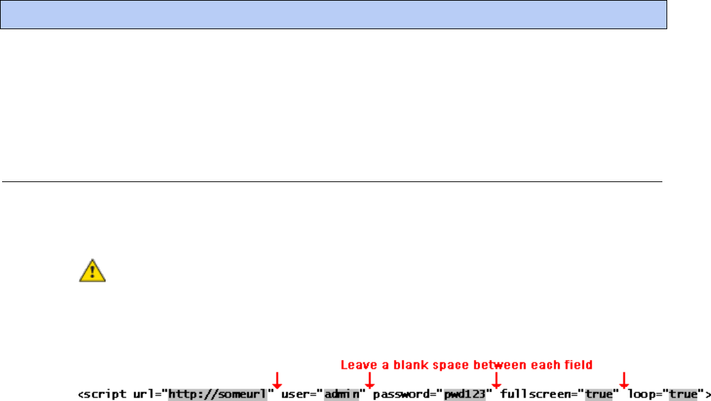
i-Vu Pro v7.0 Help CARRIER CORPORATION ©2020
All rights reserved
170
To monitor your i-Vu® Pro system, you can run the autopilot to display specified i-Vu® Pro pages at regular
intervals. You can run the autopilot on the i-Vu® Pro server or on one or more client computers. Each computer can
display a different set of pages.
REQUIREMENT You must have the Internet Explorer® web browser installed on any computer that will run the
autopilot. Autopilot is not supported on other web browsers.
To set up the i-Vu® Pro autopilot
1 Copy the i-Vu_Pro_x.x\autopilot folder from the i-Vu® Pro system to any location on the computer where you
will be running the autopilot.
2 In a text editor such as Windows
®
Notepad, open the autopilot.xml file in the new folder you created in step 1.
CAUTION Do not open or edit the original autopilot.xml file in the i-Vu® Pro system. Keep this file to set
up the autopilot on other computers.
3 In the row that begins with <script, replace the highlighted text shown below with the information needed to
start your system.
NOTES
○ The Attribute list near the top of the file describes each field.
○ To prevent exposing someone's password in this file, create a generic user and password in the i-Vu® Pro
interface.
4 Each pair of rows beginning with <navigate and <delay define a page in i-Vu® Pro and how many seconds the
page should display. Follow the steps below to replace each <navigate line with information specific to your
system. Add or delete rows as needed.
a) In the i-Vu® Pro interface, go to the page you want to display.
b) Press Ctrl+M.
c) Type autopilot location.
d) Click OK.
e) Copy the path to the Windows clipboard.
f) In the autopilot.xml file, highlight a <navigate row, then press Ctrl+V to replace the highlighted text with
the copied i-Vu® Pro path.
NOTE To have the autopilot run a report, define the path to the report's View tab.
5 In the <delay row below each path, change 20 to the number of seconds you want to display the i-Vu® Pro
page.
6 Save the file.
Running the i-Vu® Pro autopilot

i-Vu Pro v7.0 Help CARRIER CORPORATION ©2020
All rights reserved
171
To run the i-Vu® Pro autopilot
NOTE If your computer is running Windows Vista
®
, see To run autopilot with Windows Vista (page 171) before
starting the autopilot.
1 Start the i-Vu Pro Server application.
2 Run the autopilot.bat file that you created in step 1 of To set up the i-Vu® Pro autopilot (page 170).
NOTES
To stop the autopilot, do one of the following:
○ Close the web browser.
○ Close the Command Prompt window that is running the autopilot.bat file to stop the autopilot but leave
the i-Vu® Pro interface running in the web browser.
If the autopilot does not start, open autopilot.log to see the error.
To run autopilot with Windows Vista
To run the autopilot with the Windows Vista® operating system, you must add the i-Vu® Pro URL to your web
browser's trusted sites.
1 In Internet Explorer®, select Tools or > Internet Options.
2 On the Security tab, select the Trusted Sites icon, then click the Sites button.
3 Under Add this Web site to the zone, type the url that autopilot uses to start your system. See step 3 in To set
up the i-Vu® Pro autopilot (page 170).
4 Uncheck Require server verification (https:) for all sites in this zone.
5 Click Add.
6 Click OK to close both windows.
7 Close Internet Explorer to have the changes take effect.
i-Vu Pro v7.0 Help CARRIER CORPORATION ©2020
All rights reserved
172
You should perform the following system maintenance on a regular basis.
To back up a system
The type of database your system uses determines the method you use to back up the system.
CAUTION Do Not use SiteBuilder's Replicate feature to back up your database.
For Apache Derby or SQL Server Express
1 Shut down the SiteBuilder and i-Vu Pro Server applications.
2 In the i-Vu_Pro_x.x\webroot folder, copy your system folder.
3 Paste the copy to a new location.
TIP Zip the copy before transporting it over a network or to a USB drive.
For MySQL, MS SQL Server, or PostGreSQL
1 Follow the instructions above to copy your system folder in i-Vu_Pro_x.x\webroot.
2 Use the database management system's backup method. See To safely shut down the i-Vu® Pro application
for database server (page 174) maintenance before doing any maintenance on your database server.
To compact and defragment
In a new i-Vu® Pro system, the records in a database are contiguous. As records are added, deleted, and modified,
the records become scattered in the database. This condition, called fragmentation, can slow down system
performance and increase the database size. Compact the database to correct this situation.
The files on the server's hard drive can also become fragmented. Defragment the hard drive to correct this
situation.
You should compact and defragment on a regular schedule such as once a month. But, you may need to do these
more often, depending on how often the data or files change.
NOTE Compacting a database may take several minutes to several hours, depending on its size.
TIP To minimize the effects of fragmentation, you should maintain at least 20% free disk space on the server.
System database maintenance

i-Vu Pro v7.0 Help CARRIER CORPORATION ©2020
All rights reserved
173
Compacting the database
The following databases are compacted dynamically—compacting occurs in the background when a database is
open.
MySQL
MS SQL Server
MS SQL Server Express
PostGreSQL
To compact a Derby database:
1 Shut down the SiteBuilder and i-Vu® Pro Server applications.
2 Open a Windows command prompt application and type cd c:\i-Vu_Pro_x.x, replacing x.x with your
system version number.
3 Click Enter.
4 Type "Derby Compression Tool.exe" <system name>.
5 Click Enter.
6 When compacting finishes, close the command window.
Defragmenting the server's hard drive
For all database types, use a defragmentation utility such as Windows Disk Defragmenter or Norton SystemWorks.
NOTE If you are using a single computer as both the i-Vu® Pro server and the client, you must defragment the disk
more often than the disk of a dedicated server—especially if people access the Internet from this computer.
To minimize the database size
The larger a database is, the less responsive it may become. Deleting closed alarm incident groups, expired
schedules, and expired historical trends on a regular basis will reduce the database size. You can set up your i-Vu®
Pro application to automatically delete these. See "System Settings > Scheduled Tasks tab (page 281)" in i-Vu®
Pro Help.

i-Vu Pro v7.0 Help CARRIER CORPORATION ©2020
All rights reserved
174
To safely shut down the i-Vu® Pro application for database server
maintenance
Occasionally, the database server is shut down for maintenance or backups. If this is done without shutting down
the i-Vu® Pro Server first, the database may get locked and the i-Vu® Pro application may not be able to
reconnect.
1 Shut down the i-Vu® Pro application.
2 Shut down the database server.
3 Perform the maintenance or repair needed on the server.
4 Restart the database server.
5 Restart the i-Vu® Pro application.
To unlock a database
1 In SiteBuilder, click File > Open and Select Database to open your site. The following message appears The
database appears to be in use by another application ….. Do you want to override the lock?”
2 Click Yes to override the lock.
3 Log in to the site.
4 Exit SiteBuilder.
5 Start the i-Vu Pro Service.

i-Vu Pro v7.0 Help CARRIER CORPORATION ©2020
All rights reserved
175
A path tells the i-Vu® Pro application the route through the system hierarchy to an item in the system. For example,
a path tells the i-Vu® Pro application where to find a microblock property value to display on a graphic or where to
jump to when the operator clicks a link on a graphic.
In ViewBuilder, you use paths in:
Controls
Links
Conditional expressions
In i-Vu® Pro, you use paths in :
The source field code (page 93) in alarm actions and messages
An Equipment Values report (page 144)
The go manual command (page 163)
i-Vu® Pro only: Autopilot (page 170)
You can do one of the following to get the path:
In ViewBuilder, let ViewBuilder write the path.
In the i-Vu® Pro interface, determine the path yourself (page 177).
A path consists of the reference name of each tree item included in the path, separated by a forward slash (/). For
example, first_floor/zone_1/rs.
A path can be absolute (page 175) or relative (page 176).
i-Vu® Pro paths are based on parent-child hierarchy.
Absolute path
An absolute path begins at a specific point in the system hierarchy and is followed by the children below it down to
the object or property of interest. An absolute path can begin with either of the following:
A global reference name—a reference name that is unique within the entire system and begins with a # sign.
EXAMPLE If OA Conditions has a global reference name of #oa_conditions, the absolute path to OA Conditions
is simply #oa_conditions. The absolute path to any child of OA Conditions, such as OA Temperature, begins
with #oa_conditions. For example, #oa_conditions/oa_temp.
The top of the i-Vu® Pro tree.
Defining i-Vu® Pro paths

i-Vu Pro v7.0 Help CARRIER CORPORATION ©2020
All rights reserved
176
Relative path
A relative path is useful for items such as graphics or alarm messages that you will reuse in multiple i-Vu® Pro
locations because the path is relative to the item that contains the path.
A relative path going down the tree
A relative path going down the tree begins with the reference name of the item below the location where the path
is used. Examples using the system shown above:
To display the Lobby’s zone temperature on the Lobby’s graphic, the path is rs.
To display the Lobby’s zone temperature on the Atlanta-R&D Facility graphic, the path is first_floor/zone_1/rs.
A relative path going up the tree
A relative path going up the tree begins with a ~ followed by one of the options below:
Use...
To go...
Examples using the system shown above
~parent
Up one level
1 To put a link on the Lobby graphic that goes to the First
Floor graphic, the path is ~parent.
2 To put a link on the Lobby graphic that goes to the
Atlanta R&D Facility (up 2 levels), the path is
~parent/~parent.
3 To display the Lobby’s zone temperature on the Boiler
graphic, the path is ~parent/~parent/
first_floor/zone_1/rs/present_value.
~equipment
To the microblock's control
program
To display the Lobby zone temperature in a High Temp
alarm message, the path is ~equipment/rs/present_value.
~device
From a control program to its
device
To show the device name on an equipment graphic, use
~device.display-name.

i-Vu Pro v7.0 Help CARRIER CORPORATION ©2020
All rights reserved
177
Determining a path or microblock property
A path tells the i-Vu® Pro application the route through the system hierarchy to an item in the system. Paths are
used in graphics, links, alarm messages, alarm actions, network microblock address, and other items.
To get the path to an area, equipment, or microblock
In the i-Vu® Pro interface, right-click the item on the tree, then select Copy Path. Paste the path where you need it.

i-Vu Pro v7.0 Help CARRIER CORPORATION ©2020
All rights reserved
178
To get the path to a microblock property value
1 In the i-Vu® Pro interface, right-click the value, then select Global Modify.
2 Click Show Advanced to see the full path to the property value.

i-Vu Pro v7.0 Help CARRIER CORPORATION ©2020
All rights reserved
179
Using a BACnet/IP connection and an Ethernet Network Interface Card, the i-Vu® Pro server can speak BACnet/IP
over an Ethernet network.
1 On the System Options tree, select Connections.
2 On the Configure tab, select BACnet/IP Connection.
3 If the Status column shows:
○ Connected, click Disconnect.
○ Stopped or Design Mode, go to step 4.
4 Set up the fields as needed for that connection. See tables below.
5 Click Accept.
6 If running the i-Vu Pro Server (not i-Vu Pro Design Server) application, select the BACnet/IP Connection, then
click Start.
Field or button
Notes
Server IP Address
Type the server's IP address. The IP address and subnet mask must also be
set on the server's network connections page.
NOTE If the server has more than 1 NIC, use the IP address of the interface
connected to the controllers.
Server IP Subnet Mask
For default IP addressing, type 255.255.255.0.
For custom IP addressing, type the subnet mask provided by the facility
network administrator.
BACnet Port
Type 47808 unless you need to communicate with a third-party device using a
different port for BACnet communication or your IT administrator specified a
different port.
Disable Field Alarms
Select if you do not want to retain incoming alarms on this connection.
Typically this box might be checked during start-up then cleared for normal
operation.
Poll Interval
How often the i-Vu® Pro application checks the communication status of the
peer caching router. If it cannot communicate with the router, the i-Vu® Pro
application generates a Dead Module Timeout alarm.
Foreign Device
If the i-Vu® Pro server is on an IP network segment that does not have an
Carrier controller serving as a BBMD, select Force Registration. See Setting up
BBMDs (page 184).
Register with Device
If you selected Force Registration in the previous field, select the BBMD on a
remote IP network from which the i-Vu® Pro server will receive BACnet/IP
broadcasts.
Network Node
Specify which network the i-Vu® Pro server is physically connected to. This is
used to specify which BACnet/IP network the i-Vu® Pro server is on if there
are multiple BACnet/IP network nodes with different network numbers in your
system.
To set up a BACnet/IP connection in the i-Vu® Pro interface

i-Vu Pro v7.0 Help CARRIER CORPORATION ©2020
All rights reserved
180
Tuning Parameters
Notes
Comm Timeout
Amount of time, in milliseconds, that is allowed before retrying a transmission
on the network if a required acknowledgement is not received.
Comm Attempts
The number of times to try a transmission on the network.
Do Sync
Amount of time, in milliseconds, allowed for the i-Vu® Pro application to
complete a communication task such as downloading to a controller or
reading trends from a controller.
Register FD Interval
Amount of time, in seconds, that is allowed before the i-Vu® Pro application
notifies a BBMD that the i-Vu® Pro server is a foreign device to that BBMD. If
the re-registration does not occur within this time, the BBMD will delete the i-
Vu® Pro server from its list.

i-Vu Pro v7.0 Help CARRIER CORPORATION ©2020
All rights reserved
181
You can connect to the Service Port to access your network through the:
i-Vu® Pro application
Carrier touchscreen device
1 Connect an Ethernet cable from a computer to the controller's Service Port.
NOTE Be sure NOT to plug the cable into the Gig-E Port.
2 Turn off the computer's Wi-Fi if it is on.
3 If your computer uses a static IP address, use the following settings:
○ Address: 169.254.1.x, where x is 2 to 7
○ Subnet Mask: 255.255.255.248
○ Default Gateway: 169.254.1.1
4 If it uses a DHCP address, leave the address as it is.
5 Open a web browser on the computer and open your i-Vu® Pro application.
6 In the i-Vu® Pro interface, on the System Options tree, select Connections.
7 On the Properties page > Configure tab, Select BACnet/IP Service Port Connection from the drop-down list
and click Add.
8 If needed, enter the Service Port Network Number as follows:
○ 0 - the will communicate only with the computer or
○ 1 to 65534 - the 's network number for network communication
○ 65535 - searches for an available network number from 65531 to 65534. If any of these numbers are
not available, you will have to assign a network number and enter it.
9 Click Accept.
10 On the View tab, select BACnet/IP Service Port Connection from the drop-down list.
11 Click Accept.
12 On the Configure tab, select the BACnet/IP Service Port Connection and click Start. The status changes to
Connected.
To set up a BACnet/IP Service Port connection in the i-Vu® Pro interface
using an i-Vu® XT or TruVu™ device

i-Vu Pro v7.0 Help CARRIER CORPORATION ©2020
All rights reserved
182
After making sure that the Ethernet cabling has been set up properly, make sure you can ping the server from each
client computer. Then test the HTTP connection by running i-Vu Pro Design Server.
To ping the server from each client
Use the Ping utility from each client computer to test its low-level IP communication with the i-Vu® Pro server.
PREREQUISITES
An IP network connection between your server and client computers
A solid Link light and a flickering LAN light on the i-Vu® Pro client computers and the Network Interface Card
(NIC) of the i-Vu® Pro server. If either device indicates it is not on the network, see Troubleshooting the
Ethernet connections
After the link and the LAN lights on the server’s NIC and on the client are lighting properly, ping the i-Vu® Pro
server from each client machine.
1 At the Command Prompt, type the following command: ping xxx.xxx.xxx.xxx [Enter], where
xxx.xxx.xxx.xxx is the IP address of the device you are pinging.
The reply should indicate that a device with address xxx.xxx.xxx.xxx is present and passing IP packets on the
network.
EXAMPLE For a device with an IP address of 192.168.168.100, type the following:
ping 192.168.168.100
TIP To continuously ping a device, type the following command: ping xxx.xxx.xxx.xxx -t.
Press Ctrl+C to stop the ping command.
2 If you receive the reply Request timed out or you do not receive a reply, contact the facility’s network
administrator to check the NIC, the hub's settings, and the IP configuration settings. You do not have a valid IP
connection between the 2 devices.
To test the HTTP connection
i-Vu Pro Design Server does not attempt communication with field hardware, so you can isolate client-to-server
issues from server-to-field issues.
1 Click Start > All Programs > i-Vu_Pro_ x.x > i-Vu Pro Design Server.
2 From each client computer, start the web browser, then type the IP address of the server in the Address field.
If the i-Vu® Pro login screen does not appear, contact the facility's network administrator.
Testing the server-to-client connections

i-Vu Pro v7.0 Help CARRIER CORPORATION ©2020
All rights reserved
183
If the system is running, go to Driver Properties > Devices page from different levels of the navigation tree to view
the status of your communication networks and controllers. If you detect a networking problem with an Ethernet
connection, see Troubleshooting an Ethernet connection.
After making sure that the Ethernet cabling has been set up properly, use the Ping utility from the i-Vu® Pro server
to test its low-level IP communication with each controller on the IP network, then obtain a Modstat (page 190)
from each controller to ensure its BACnet communication with the i-Vu® Pro server.
To ping a controller on the IP network from the i-Vu® Pro server
Use the Ping utility to test low-level IP connections between the server and each controller on the IP network.
PREREQUISITES
An IP network connection between the server and the Carrier controller.
A solid link light and a flickering LAN light on the Carrier controller and the i-Vu® Pro server's Network
Interface Card (NIC). See Troubleshooting an Ethernet connection.
After the link and LAN lights on the server’s NIC and on the controller are lighting properly, ping each controller
from the i-Vu® Pro server.
1 At the Command Prompt, type the following command: ping xxx.xxx.xxx.xxx [Enter], where
xxx.xxx.xxx.xxx is the IP address of the device you are pinging.
The reply should indicate that a device with address xxx.xxx.xxx.xxx is present and passing IP packets on the
network.
EXAMPLE For a device with an IP address of 192.168.168.100, type the following:
ping 192.168.168.100
TIP To continuously ping a device, type the following command: ping xxx.xxx.xxx.xxx -t.
Press Ctrl+C to stop the ping command.
2 If you receive the reply Request timed out or you do not receive a reply, contact the facility’s network
administrator to check the NIC, the hub's settings, and the IP configuration settings. You do not have a valid IP
connection between the 2 devices.
Testing the server-to-controller connections

i-Vu Pro v7.0 Help CARRIER CORPORATION ©2020
All rights reserved
184
To minimize network communications, IP routers do not pass on broadcasts that they receive. If your system has
<control-module>s on different IP subnets separated by an IP router, you must set up a BACnet router on each IP
subnet as a BACnet Broadcast Management Device (BBMD). A BBMD passes BACnet/IP broadcasts across the IP
router to other BBMDs.
IP subnet
R
BBMD
172.18.1.1 172.16.1.1
IP Router
Controller Controller
IP subnet
BBMD
The following Carrier BACnet routers can function as a BBMD on an IP subnet:
Open routers:
i-Vu® XT or TruVu™ routers:
i-Vu® Open Link
i-Vu® Open Router
i-Vu® XT or TruVu™ Router
i-Vu® XT or TruVu™ BACnet
Link
To set up BBMDs, use the appropriate method in the table below.
If your i-Vu® Pro system has...
Use this method
Fewer than 100 IP subnets with no third-party BACnet routers*
Let SiteBuilder automatically configure
your BBMDs.
Any of the following:
More than 100 IP subnets*
Carrier controllers on an IP subnet that has a third-party
BBMD
Carrier controllers that need to communicate with third-
party devices on a different IP subnet
Set up custom BBMDs in the i-Vu® Pro
interface or in the BBMD Configuration
Tool.
* If your system has only i-Vu® XT or TruVu™ routers, this number changes from 100 to 500.
NOTE If the i-Vu® Pro server is on an IP subnet without the Carrier BACnet router, register the server as a foreign
device. See To set up the i-Vu® Pro server as a foreign device (page 188).
Setting up BACnet Broadcast Management Devices (BBMDs)

i-Vu Pro v7.0 Help CARRIER CORPORATION ©2020
All rights reserved
185
To set up BBMDs in SiteBuilder
As you add each Carrier BACnet router to an IP network on the Network tree, check Automatically Configure My
BBMDs on the Address tab. SiteBuilder automatically selects a router in each IP subnet as the BBMD and sets up
BBMD tables appropriately.
To see which BACnet routers SiteBuilder assigned as BBMDs, select View > Display > BBMD. BBMDs show
B=assigned on the Network tree.
To override SiteBuilder's BBMD selection, right-click a different BACnet router on the same IP subnet, then select
Force to BBMD.
NOTE If you are managing 3rd party BBMDs, you must add every 3rd party device that could be a BBMD as a 3rd
party device router in SiteBuilder.
To set up BBMDs through the i-Vu® Pro interface
1 Make a list of the IP addresses for every controller that will function as a BBMD in your system.
CAUTION Multiple BBMDs on an IP subnet disrupt BACnet communications. Define only one BBMD on
either side of each IP router in your system.
2 In Notepad, type the list putting each IP address on a separate line. (Open routers support up to 100 IP
addresses per .bdt file; i-Vu® XT or TruVu™ routers support up to 500.)
NOTE If you must communicate with a third-party router that does not use the BACnet/IP port 47808
(0xbac0), you must include the hexadecimal port number in the IP address. For example,
172.168.23.67:0xe78a
3 Save the file in the webroot\<system_name> folder with a .bdt extension instead of .txt.
4 On the i-Vu® Pro navigation tree, select one of the Carrier controllers that will function as a BBMD.
5 To check if the controller has an existing BBMD table, click and select Manual Command.
6 In the manual command field, type: bbmd read x.x.x.x
where x.x.x.x is the IP address of the controller you are on.

i-Vu Pro v7.0 Help CARRIER CORPORATION ©2020
All rights reserved
186
7 Click OK.
8 If the Broadcast Distribution Table contains IP addresses that are not in your .bdt file, add them to your .bdt
file.
9 Click and select Manual Command.
10 In the manual command field, type: bbmd write filename.bdt x.x.x.x
where filename.bdt is the .bdt file in the webroot\<system_name> folder
and x.x.x.x is the IP address of the controller you are on.
11 Click OK.
12 Issue another bbmd read command to verify that the .bdt file was written correctly.
To set up BBMDs using the BBMD Configuration Tool
Before you begin, do the following:
○ Set up the IP address, subnet mask, default gateway, and network numbers for the i-Vu® Pro server and
each Carrier controller on the IP network.
○ The BBMD Configuration Tool is available on the i-Vu® Tech Tools USB drive or go to
http://www.hvacpartners.com.

i-Vu Pro v7.0 Help CARRIER CORPORATION ©2020
All rights reserved
187
1 Make a list of the IP addresses for every controller that will function as a BBMD in your system.
CAUTION Multiple BBMDs on an IP subnet disrupt BACnet communications. Define only one BBMD on
either side of each IP router in your system.
2 In Notepad, type the list putting each IP address on a separate line. (Open routers support up to 100 IP
addresses per .bdt file; i-Vu® XT or TruVu™ routers support up to 500.)
NOTE If you must communicate with a third-party router that does not use the BACnet/IP port 47808
(0xbac0), you must include the hexadecimal port number in the IP address. For example,
172.168.23.67:0xe78a
3 Save the file in the webroot\<system_name> folder with a .bdt extension instead of .txt.
4 Open the BBMD Configuration Tool.
5 In the IP Address or Host Name field, type the IP address of an Carrier controller that functions as the BBMD
(BACnet Broadcast Management Device) for its subnet.
6 Click the Broadcast Distribution Table Read button to see if the controller has an existing BBMD table. The
information found is displayed in the bottom half of the window.
7 If the Broadcast Distribution Table contains IP addresses that are not in the .bdt file you created in steps 2
and 3, add them to your .bdt file.
8 Verify that the same controller IP address is still in the IP Address or Host Name field.
9 Click the Broadcast Distribution Table Browse button, then select the .bdt file that you created in steps 2 and
3.
10 Click the Broadcast Distribution Table Write button to send the information to the controller.
11 Click Read again to verify that the new .bdt file was written to the Carrier controller.

i-Vu Pro v7.0 Help CARRIER CORPORATION ©2020
All rights reserved
188
12 Repeat steps 5 through 11 for each Carrier controller that will function as a BBMD in your system.
To set up the i-Vu® Pro server as a foreign device
If the i-Vu® Pro server is on an IP subnet without an Carrier BACnet router, register the server as a foreign device to
a BBMD in the system. That BBMD will then forward BACnet broadcasts to the server. Register the server with the
BBMD that will have the fastest response time. Response time is affected by distance and network complexity.
1 Click > System Options > Connections.
2 On the Configure tab, select BACnet/IP Connection.
3 If the Status column shows:
○ Connected, click Disconnect.
○ Stopped or Design Mode, go to step 4.
4 Type the i-Vu® Pro server's IP address in the IP Address field. (172.18.64.37, in the example above.)
NOTE If you have more than one network interface card, type the address that connects to the controller
network.
5 Type the i-Vu® Pro server's subnet mask in the IP Subnet Mask field. (255.255.0.0, in the example above.)
6 Select Force Registration from the Foreign Device drop-down list.
7 Select the BBMD in the Primary BBMD field.
8 To have a backup in case the first BBMD fails, select another BBMD in the Backup BBMD if primary fails field.
9 Click next to Tuning Parameters.
10 Keep the 600-second default value in the Register FD Interval field.
NOTE If the re-registration does not occur within this time, the BBMD will delete the i-Vu® Pro server from its
list.
11 Click OK.
12 If running i-Vu® Pro Server (not i-Vu® Pro Design Server), select the BACnet/IP Connection, then click Start.
i-Vu Pro v7.0 Help CARRIER CORPORATION ©2020
All rights reserved
189
If your system does not have any BBMDs
Follow the steps below to create pseudo BBMDs so that you can register the server.
1 In the SiteBuilder application, double-click each BACnet router and check Automatically Configure My BBMDs
on the Address tab.
2 In the i-Vu® Pro application, select any location on the navigation tree.
3 Run the manual command bbmd update to create a blank .bdt table in every router and mark them for
download.
4 Download parameters to the routers.
5 Follow the steps above to register the i-Vu® Pro server as a foreign device to one of the routers.

i-Vu Pro v7.0 Help CARRIER CORPORATION ©2020
All rights reserved
190
A Modstat (Module Status) provides information about a controller and verifies proper network communication with
the controller.
To obtain a Modstat
You can get a controller's ModStat in the following places:
Open device—In the i-Vu® Pro or SiteBuilder application
i-Vu® XT or TruVu™ device—In the i-Vu® Pro application or the controller's setup pages
In the i-Vu® Pro application
Use one of the following methods:
Right-click a router or controller on the navigation tree, then select Module Status.
Select a router on the navigation tree. On the Properties page, click Module Status.
NOTE You cannot get a Modstat if running i-Vu Pro Design Server because it cannot communicate with controllers.
In the SiteBuilder application (Open device only)
1 Use a USB Link Kit to connect your computer to the controller's Local Access port. See To connect to a
device's Local Access port (page 195).
2 In SiteBuilder, select Configure > Preferences.
3 On the Connections tab, select the computer Port that the USB Link Kit cable is connected to, and Baud Rate
to the Rnet port at 115200.
4 Right-click the controller in SiteBuilder's Network tree, then select Module Status.
Using a Modstat to troubleshoot your system

i-Vu Pro v7.0 Help CARRIER CORPORATION ©2020
All rights reserved
191
In the controller's setup pages (i-Vu® XT or TruVu™ device only)
1 Connect an Ethernet cable from a computer to the controller as shown below.
2 Turn off the computer's Wi-Fi if it is on.
3 If your computer uses a static IP address, use the following settings:
○ Address: 169.254.1.x, where x is 2 to 7
○ Subnet Mask: 255.255.255.248
○ Default Gateway: 169.254.1.1
4 If it uses a DHCP address, leave the address as it is.
5 Open a web browser on the computer.
6 Navigate to http://local.access or http://169.254.1.1 to see the Service Port controller setup pages.
Modstat field descriptions
NOTE Modstats vary for different types of controllers. The list below describes all information that could appear on
any Modstat. If a description differs between different generations of controllers, the generation is noted.
Field
Description
Date/Time
Date and time the Modstat was run
CM
The controller's rotary switch address (MAC address)
Model Name
Identifies the Product Type
Device Instance
A unique ID assigned to the controller
Driver built
When the driver was built
Downloaded by
When and where the last download was performed
Application Software Version
The name of the first control program that is downloaded

i-Vu Pro v7.0 Help CARRIER CORPORATION ©2020
All rights reserved
192
Field
Description
Flash Archive Status
Shows the validity, date, and time of the most recent archive of
parameters and status to the controller's permanent flash memory.
The archive takes place once a day.
# PRGs initialized
# PRGs running
If applicable, the number of control programs that were downloaded
vs. the number that are running. If these numbers are not the same,
the controller has a problem such as lack of memory.
Firmware sections in flash
memory
The name, version, and date of the driver
Reset Counters:
Open device: The number of times each of the following events have
occurred since the last time the controller was formatted.
i-Vu® XT or TruVu™ device: The number of times each of the following
events have occurred since the last time the controller was
commanded to clear the reset counters.
See NOTE below this table.
Power failures
Interruption of incoming power
Brownouts
Low-level incoming power
Commanded boots
Includes commands issued from the i-Vu® Pro interface such as the
zap manual command, plus commands issued during a memory
download.
System errors
Error in the controller's firmware or hardware
Watchdog timeouts
Watchdog is firmware that monitors the firmware for normal
operation. If watchdog detects a problem, it restarts the firmware.
S/W Watchdog
timeouts
Watchdog is firmware that monitors the application firmware for
normal operation. If the watchdog firmware detects a problem, it
restarts the application firmware.
H/W Watchdog
timeouts
H/W Watchdog will restart the controller if it detects a severe problem
with the controller's operating system
System status
Gives the current status of the controller's operation.
Network status
Gives the current status of the controller's networks.
System error message history
Open device: High-severity errors since the last memory download or
format. Shows the first 5 and last 5 messages.
i-Vu® XT or TruVu™ device: High-severity errors since the last memory
download. Shows the most recent 10 messages.
See NOTE below this table.
Warning message history
Open device: Low-severity errors and warning messages since the last
memory download or format. Shows the first 5 and last 5 messages.
i-Vu® XT or TruVu™ device: Low-severity errors and warning messages
since the last memory download. Shows the most recent 10
messages.
See NOTE below this table.

i-Vu Pro v7.0 Help CARRIER CORPORATION ©2020
All rights reserved
193
Field
Description
Information message history
Open device: Information-only messages since the last memory
download or format. Shows the first 5 and last 5 messages.
i-Vu® XT or TruVu™ device: Information-only messages since the last
memory download. Shows the most recent 10 messages.
See NOTE below this table.
Manifest revision
Firmware revision
Installed bundles
Components of the firmware
ARC156 reconfigurations during
the last hour
An ARCNET network normally reconfigures itself when a controller is
added to or taken off the network. The Total field indicates the
number of reconfigurations in the last hour. Initiated by this node
indicates the number of reconfigurations initiated by this controller.
Typical sources of the problem could be this controller, the controller
with the next lower rotary switch address, any controller located on
the network between these two controllers, or the wiring between
these controllers. An excessive number in these fields indicates a
problem with the network.
BACnet comm errors in the last 7
days
BACnet communication errors usually indicating dropped packets
caused by high traffic on network.
Core (or Main) and Base board
hardware
Gives the following information about the controller's boards:
Type and board numbers that are used internally by Carrier.
The manufacture date and serial number.
Open device only: The core board's RAM and Flash memory.
RAM is used for driver and control program executables.
Flash memory is used for firmware and file storage. See Flash
storage size below.
Number of BACnet objects
The number of BACnet objects that were created in the device and the
number of those objects that are network visible.
Largest free heap space
Size of the largest piece of unused dynamic memory
Database size
Open device: Size of the controller's memory designated for running
programs. Database memory is used for control program parameters,
status and history; trends, schedules, and alarms; and driver
parameters, status and history.
i-Vu® XT or TruVu™ device: Size of the controller's memory.
Flash storage size
The size of the flash memory that is not used by the firmware. This
memory is used for file storage and archiving.
Archive storage size
The amount of flash memory remaining for archival after files are
downloaded.
File storage size
The size of all files (control programs, graphics, driver, etc.)
downloaded to the controller. How much information is in these files
depends on whether the controller's Download source files option is
selected in SiteBuilder or i-Vu® Pro.
Raw physical switches
The readings used to test the DIP or rotary switches

i-Vu Pro v7.0 Help CARRIER CORPORATION ©2020
All rights reserved
194
Field
Description
Network Information
Open device: The various network addresses for a controller installed
on an Ethernet. The Current and Assigned addresses will be the
same unless:
The Assigned addresses were changed in PuTTY.
The controller's DHCP/Assigned DIP switch was moved to the
DHCP position after the Assigned addresses were defined in
SiteBuilder.
The Enable IP configuration changeover on the BACnet Router
Properties page is being implemented.
i-Vu® XT or TruVu™ device: The various network addresses for the
controller. The Current and Assigned addresses will be the same
unless the Enable IP configuration changeover on the BACnet Router
Properties page is being implemented.
Route Information
BACnet networks that a router is currently routing traffic to. The list
changes as BACnet routers are added or removed from the system.
Ethernet statistics
Diagnostic counters directly related to the ethernet communications
hardware.
NOTE i-Vu® XT or TruVu™ device only—If you want to clear the Reset counters and the three message history
fields, click the Clear Counts/Logs button on the controller's Properties page in the i-Vu® Pro application or in the
i-Vu® XT or TruVu™ device's setup pages that you access through the Service Port.

i-Vu Pro v7.0 Help CARRIER CORPORATION ©2020
All rights reserved
195
You can connect locally to controllers and some sensors to commission, start up, or troubleshoot equipment, or
download to controllers. Use a local connection in any of the following situations:
The entire network is not yet functional.
The permanent i-Vu® Pro server is not operating.
The server is operating, but you don't have a convenient IP connection.
To make a local connection, use a USB Link to connect a laptop running either the:
i-Vu® Pro application - Requires a copy of the system database and that you set up a Local Access connection
in the i-Vu® Pro interface (page 197).
Field Assistant application - Use this option if more than one person is starting up the system. See Field
Assistant Help for more information.
To connect to a device's Local Access port
PREREQUISITES
A computer with a USB port
A USB Link cable
NOTE The USB Link driver is installed with i-Vu® Pro v5.1 or later systems. But if needed, you can get the
latest driver from http://www.silabs.com/products/mcu/Pages/USBtoUARTBridgeVCPDrivers.aspx. Install the
driver before you connect the USB Link to your computer
CAUTION If multiple controllers share power but polarity was not maintained when they were wired, the
difference between the controller's ground and the computer's AC power ground could damage the USB Link and
the controller. If you are not sure of the wiring polarity, use a USB isolator between the computer and the USB Link.
Purchase a USB isolator online from a third-party manufacturer.
1 Connect the computer to the local access port of the controller, ZS sensor, or an SPT sensor using the USB
Link cable(s).
USB Link
Connect to
Local Access port
12 ft
Connect to
USB port
7 3/4 in.
NOTE If using a USB isolator, plug the isolator into your computer's USB port, and then plug the USB Link
cable into the isolator.
Communicating locally with Open devices

i-Vu Pro v7.0 Help CARRIER CORPORATION ©2020
All rights reserved
196
2 i-Vu® Open Router or i-Vu® Open Link only: Turn off the router's power, set its Router Config Mode DIP switch
to ON, then turn its power on again.
3 In SiteBuilder, set your Configure > Preferences > Connections tab settings.
To communicate with...
Set switch to...
The i-Vu® Pro application
Off
PuTTY or HyperTerminal
On
SiteBuilder to set a custom IP address
On
4 When you are through communicating with the Local Access port, be sure to return the Router Config Mode
DIP switch to its original setting.
NOTES
Using a Local Access port does not interrupt the delivery of alarm and trend notifications to the controller's
specified BACnet Alarm Recipient.
You cannot use a Local Access port to set up BBMDs because Local Access connections do not communicate
using BACnet/IP.
A router must be present to receive colors from the controller network.
Troubleshooting a Local Access connection
Inability to communicate over a Local Access connection may cause the following symptoms:
Question marks on i-Vu® Pro Properties pages and Graphics pages
Cannot obtain a Modstat from the connected controller
Controller Status report displays purple for a connected BACnet/IP controller
Cannot download to connected controller
A message says Local Access is disabled or unable to connect.
No controllers found in i-Vu® Pro

i-Vu Pro v7.0 Help CARRIER CORPORATION ©2020
All rights reserved
197
Possible cause
Solution
Network number in
SiteBuilder does not match
the number found in the
controller
Use the rnet here manual command to force the local device to accept
the next download applied.
1 Click , then select Manual Command.
2 In the manual command field, type rnet here.
3 Download Parameters or All Content to the controller to which you are
connected.
4 On the i-Vu® Pro navigation tree, select the controller.
5 On the Properties page, click Module Status to verify communication with
the controller.
i-Vu® Pro communication
timeout settings are not
sufficient for your network
configuration.
Increase your communication timeout settings.
1 On the System Options tree, select Connections.
2 On the Configure tab, select BACnet/Rnet Connection.
3 Click the plus sign (+) next to Tuning Parameters.
4 Double the values in the Comm Timeout and Comm Attempts fields.
NOTE If changing these values does not fix your intermittent communication,
contact Carrier Control Systems Support.
Selected COM port is in use
Shut down other applications such as PuTTY that may be running and holding
the port open.
Baud rates are inconsistent
Verify that the Silicon Labs CP210x USB to UART Bridge and the i-Vu® Pro
application are using the baud rate used by the controller.
To set up a Local Access connection
To set up communication between the i-Vu® Proapplication on your laptop and the controller:
1 Click and select System Options > Connections.
2 On the Configure tab, click Add.
3 From the Type drop-down list, select BACnet/Rnet Connection.
4 Optional: Edit the Description.

i-Vu Pro v7.0 Help CARRIER CORPORATION ©2020
All rights reserved
198
5 Type the computer's Port number that the USB cable is connected to.
NOTE To find the port number, plug the USB cable into the computer's USB port, then select Start > Control
Panel > System > Device Manager > Ports (Com & LPT). The COM port number is beside Silicon Labs
CP210x USB to UART Bridge.
6 Set the Baud rate.
Local Access port
Baud Rate
5-pin
115200
7 Click Accept.
8 On the View tab, select BACnet/Rnet Connection from the drop-down list.
9 Click Accept.
10 On the Configure tab, select BACnet/Rnet Connection, then click Start.
NOTE If an error message appears, make sure the COM port you selected is not in use. For example, PuTTY
may be open and is holding the port open.
11 If using the 5-pin Local Access port, on the navigation tree, select the controller that you are connected to.
12 Click and select Manual Command.
13 Type rnet here in the dialog box, then click OK.
14 On the Properties page, click Module Status. If a Modstat (page 190) report appears, the i-Vu® Pro
application is communicating with the controller.

i-Vu Pro v7.0 Help CARRIER CORPORATION ©2020
All rights reserved
199
You can connect a laptop to the i-Vu® XT or TruVu™ device's:
Service port to set up the controller's address, ports, protocols, baud rates, or to communicate with the i-Vu®
Pro application
Rnet port to commission, download, and troubleshoot equipment through i-Vu® Pro or Field Assistant
To communicate with the i-Vu® XT or TruVu™ device's Service Port
Using a computer and an Ethernet cable, you can communicate with the i-Vu® XT or TruVu™ device's setup pages
through a web browser to:
View the controller's Module Status report
View/change controller and network settings
Set up ports, protocols, and baud rates
Communicate with the i-Vu® Pro application (See To set up a BACnet/IP Service Port connection in the i-Vu®
Pro interface (page 181)
Troubleshoot
The information shown on the controller setup pages is specific to the controller. See the controller's Technical
Instructions for details.
1 Connect an Ethernet cable from a computer to the controller as shown below.
2 Turn off the computer's Wi-Fi if it is on.
3 If your computer uses a static IP address, use the following settings:
○ Address: 169.254.1.x, where x is 2 to 7
○ Subnet Mask: 255.255.255.248
○ Default Gateway: 169.254.1.1
Communicating locally with i-Vu® XT or TruVu™ devices

i-Vu Pro v7.0 Help CARRIER CORPORATION ©2020
All rights reserved
200
4 If it uses a DHCP address, leave the address as it is.
5 Open a web browser on the computer.
6 Navigate to http://local.access or http://169.254.1.1 to see the Service Port controller setup pages.
To communicate locally through the i-Vu® XT or TruVu™ device's Rnet
port
You can connect a computer to the i-Vu® XT or TruVu™ device's Rnet port to commission, download, and
troubleshoot equipment through the i-Vu® Pro application or Field Assistant.
PREREQUISITES
A computer with a USB port
A USB Link cable
NOTES
○ The USB Link driver is installed with i-Vu® Pro v5.1 or later systems. But if needed, you can get the latest
driver from http://www.silabs.com/products/mcu/Pages/USBtoUARTBridgeVCPDrivers.aspx. Install the
driver before you connect the USB Link to your computer
○ You will use only the portion of the USB Link that has the USB connector.
CAUTION If multiple controllers share power but polarity was not maintained when they were wired, the
difference between the controller's ground and the computer's AC power ground could damage the USB Link
and the controller. If you are not sure of the wiring polarity, use a USB isolator between the computer and the
USB Link. Purchase a USB isolator online from a third-party manufacturer.
A 3-pin screw terminal connector and 3-wire cable
1 Connect one end of a piece of 3-wire cable to the 3-pin connector.

i-Vu Pro v7.0 Help CARRIER CORPORATION ©2020
All rights reserved
201
2 Connect the other end of the 3-wire cable to the 's Rnet port as shown in the drawing above in step 1.
Connect the 3-pin connector to the portion of the USB Link shown in the drawing below, then connect the USB
connector to the computer.
NOTE If using a USB isolator, plug the isolator into your computer's USB port, and then plug the USB Link
cable into the isolator.
To set up a BACnet/Rnet connection in the i-Vu® Pro interface
To set up communication between the i-Vu® Proapplication on your laptop and the controller:
1 Click and select System Options > Connections.
2 On the Configure tab, click Add.
3 From the Type drop-down list, select BACnet/Rnet Connection.
4 Optional: Edit the Description.
5 Type the computer's Port number that the USB cable is connected to.
NOTE To find the port number, plug the USB cable into the computer's USB port, then select Start > Control
Panel > System > Device Manager > Ports (Com & LPT). The COM port number is beside Silicon Labs
CP210x USB to UART Bridge.
6 Set the Baud rate.
Local Access port
Baud Rate
5-pin
115200
7 Click Accept.
8 On the View tab, select BACnet/Rnet Connection from the drop-down list.

i-Vu Pro v7.0 Help CARRIER CORPORATION ©2020
All rights reserved
202
9 Click Accept.
10 On the Configure tab, select BACnet/Rnet Connection, then click Start.
NOTE If an error message appears, make sure the COM port you selected is not in use. For example, PuTTY
may be open and is holding the port open.
11 If using the 5-pin Local Access port, on the navigation tree, select the controller that you are connected to.
12 Click and select Manual Command.
13 Type rnet here in the dialog box, then click OK.
14 On the Properties page, click Module Status. If a Modstat (page 190) report appears, the i-Vu® Pro
application is communicating with the controller.
Troubleshooting an Rnet connection
Inability to communicate over a Local Access connection may cause the following symptoms:
Question marks on i-Vu® Pro Properties pages and Graphics pages
Cannot obtain a Modstat from the connected controller
Controller Status report displays purple for a connected BACnet/IP controller
Cannot download to connected controller
A message says Local Access is disabled or unable to connect.
No controllers found in i-Vu® Pro
Possible cause
Solution
Network number in
SiteBuilder does not match
the number found in the
controller
Use the rnet here manual command to force the local device to accept
the next download applied.
1 Click , then select Manual Command.
2 In the manual command field, type rnet here.
3 Download Parameters or All Content to the controller to which you are
connected.
4 On the i-Vu® Pro navigation tree, select the controller.
5 On the Properties page, click Module Status to verify communication with
the controller.

i-Vu Pro v7.0 Help CARRIER CORPORATION ©2020
All rights reserved
203
Possible cause
Solution
i-Vu® Pro communication
timeout settings are not
sufficient for your network
configuration.
Increase your communication timeout settings.
1 On the System Options tree, select Connections.
2 On the Configure tab, select BACnet/Rnet Connection.
3 Click the plus sign (+) next to Tuning Parameters.
4 Double the values in the Comm Timeout and Comm Attempts fields.
NOTE If changing these values does not fix your intermittent communication,
contact Carrier Control Systems Support.
Selected COM port is in use
Shut down other applications such as PuTTY that may be running and holding
the port open.
Baud rates are inconsistent
Verify that the Silicon Labs CP210x USB to UART Bridge and the i-Vu® Pro
application are using the baud rate used by the controller.

i-Vu Pro v7.0 Help CARRIER CORPORATION ©2020
All rights reserved
204
Your i-Vu® Pro building automation system's controllers and server should be as secure as possible. However,
achieving this security can be challenging because of the complexities of networks, firewalls, and virtual private
networks (VPN's). Two means for increasing the security of your system are:
While the i-Vu® Pro server was designed to be secure, BACnet is an open protocol that can pose risks for the
controllers. The most secure system is one that is completely isolated from the Internet, but that is not always
possible. The v6-02 or later drivers for Carrier controllers with Ethernet capability have a BACnet firewall
feature that allows you to restrict communication with the controller to all private IP addresses and/or to a
whitelist of IP addresses that you define. To set this up, go to the navigation tree > right-click the router >
Driver Properties > Bacnet Firewall. Follow the instructions in the interface.
You should use TLS (HTTPS, not HTTP) to secure the client device that you are using to connect to the i-Vu®
Pro server. See What is TLS (HTTPS)? (page 204) for instructions on setting up TLS.
For information on secure network configurations, options, and best practices, see the following documents on the
Carrier support website.
Security Best Practices
Security Letter
What is TLS (HTTPS)?
The i-Vu® Pro application supports Transport Layer Security (TLS), a secure protocol used for transmitting private
information over the Internet using HTTPS.
NOTE TLS is a more recent version of Secure Sockets Layer (SSL).
TLS uses a method called public-key cryptography to provide:
Client/server authentication before transmitting data.
128-bit encryption of all data before it is transmitted over the TLS connection and decryption of the data upon
receipt.
Public key cryptography uses keys and certificates to authenticate users. The keys and certificates are protected
with a keystore password.
You have 2 options for creating a certificate. You can use:
A certificate from a trusted Certificate Authority (CA). This option provides the most security because the CA
performs the authentication. See To set up TLS using a Certificate Authority (CA) certificate (page 205).
A self-signed certificate. This option is quicker and easier to set up, but is less secure. See To set up TLS using
a self-signed certificate (page 210).
Network security

i-Vu Pro v7.0 Help CARRIER CORPORATION ©2020
All rights reserved
205
To increase the encryption level to 256-bit
NOTE To increase the encryption level, you must accept and adhere to Oracle's License Agreement, and be in a
country that is not subject to import control restrictions.
1 Go to http://www.oracle.com/technetwork/java/javase/downloads/index.html
(http://www.oracle.com/technetwork/java/javase/downloads/index.html).
2 Click the Download button for Java Cryptography Extension (JCE) Unlimited Strength Jurisdiction Policy Files
for JDK/JRE 8.
3 Read and accept the Binary Code License Agreement for the Java SE Platform Products.
4 Download JCE-policy-8.zip. This .zip file contains 2 policy files: local_policy.jar and US_export_policy.jar.
5 Put the 2 .jar files in the <i-Vu_Pro__Install>\bin\java\jre\lib\security folder, replacing the 2 existing files
with the same names.
To set up TLS using a Certificate Authority (CA) certificate
NOTES
TLS is a more recent version of Secure Sockets Layer (SSL).
For a list of trusted Certificate Authorities, open Internet Explorer, then select Tools or > Internet Options >
Content > Certificates > Trusted Root Certificate Authorities.
Step 1: Create a key and certificate
1 In SiteBuilder, select Configure > Preferences > Web Server.
2 Select HTTPS Only in the Enabled Web Server Ports field.
NOTE For quicker navigation, select Both HTTP and HTTPS if operators will connect to the system from an
internal network and the Internet. Change the setting in the HTTPS Port field only if the system will be using a
non-standard port.
3 Click Delete Certificate.
CAUTION Clicking this button will delete all certificates in your system.
4 Click Make Certificate.
5 In the Make Certificate dialog box, type a Keystore password.
i-Vu Pro v7.0 Help CARRIER CORPORATION ©2020
All rights reserved
206
6 In the DNS name of your server field, type the address of the server using one of the following formats:
• The domain name if accessing through the Internet. Example: www.abi.com.
• The IP address if accessing through the Internet. Example: 216.227.49.36.
• The computer name if accessing internally. Example: mycomputerxp.
NOTES
○ The address format you use in this field is the format operators must use to access the system in a web
browser.
○ The entered names will be used as the Subject Alt Names in the certificate.
○ You can enter more then one name. Separate the names by a comma and no spaces.
7 The next 5 fields are optional, but the more information you enter, the more secure your key is.
8 Click Apply.
9 In the Keystore Password field, type the password that you entered in step 5 above.
NOTE This field is case sensitive.
10 Click OK.
Step 2: Obtain a CA certificate
1 Create a Certificate Signing Request (CSR).
a) In the i-Vu® Pro server's Start menu, select All Programs > Accessories > Command Prompt.
b) Type the following command as a single line of text, replacing <x.x> with the system's version number:
C:\i-Vu_Pro_<x.x>\bin\java\jre\bin\keytool.exe -certreq -alias i-Vu Pro -
keystore C:\i-Vu_Pro_<x.x>\webserver\keystores\certkeys -file C:\i-
Vu_Pro_<x.x>\webserver\keystores\request.csr
c) Press Enter. This creates a request.csr file located in C:\i-Vu_Pro_x.x\webserver\keystores.
2 Get a certificate from a certificate authority (typically from their website). The CA will ask you to send a copy of
the CSR file (request.csr). Or, the CA may ask you to paste the contents of the request.csr file into their
website.
3 You will receive the following files from your CA. Copy these .cer files to the i-Vu_Pro_x.x folder:
A chain or root certificate
One or more intermediate certificates (Not all CA's provide intermediate certificates.)
A received certificate
See NOTE at the bottom of this topic.
4 Import the root certificate.
a) In the i-Vu® Pro server's Start menu, select All Programs > Accessories > Command Prompt.
b) Type the following command as a single line of text, replacing <x.x> with the system's version number and
<root.cer> with the name of the root certificate file:
C:\i-Vu_Pro_<x.x>\bin\java\jre\bin\keytool.exe -import -trustcacerts -
alias root -keystore C:\i-Vu_Pro_<x.x>\webserver\keystores\certkeys -file
\i-Vu_Pro_<x.x>\<root.cer>
i-Vu Pro v7.0 Help CARRIER CORPORATION ©2020
All rights reserved
207
c) Press Enter.
d) The information for the root key is displayed and you are prompted to trust this certificate. Type yes.
5 If the CA provided an intermediate certificate, import that certificate.
a) In Command Prompt, type the following command as a single line of text, replacing <x.x> with the
system's version number and <intermediate.cer> with the name of the intermediate certificate file:
C:\i-Vu_Pro_<x.x>\bin\java\jre\bin\keytool.exe -import -trustcacerts -
alias intermed -keystore C:\i-Vu_Pro_<x.x>\webserver\keystores\certkeys -
file \i-Vu_Pro_<x.x>\<intermediate.cer>
b) Press Enter.
NOTE If the CA provided more than one intermediate certificate, repeat step 5 for each one. Replace -
alias intermed with -alias intermed1, -alias intermed2, etc.
6 Import the received certificate.
a) In Command Prompt, type the following command as a single line of text, replacing <x.x> with the
system's version number and <received.cer> with the name of the received certificate file:
C:\i-Vu_Pro_<x.x>\bin\java\jre\bin\keytool.exe -import -trustcacerts -
alias i-Vu_Pro_ -keystore C:\i-Vu_Pro_<x.x>\webserver\keystores\certkeys -
file \i-Vu_Pro_<x.x>\<received.cer>
b) Press Enter.
NOTE If you are not sure which file is which certificate, double click each .cer file. Go to the Certificate Path tab. If
you see:
Only 1 entry, this is your root certificate.
Multiple entries but the last one is your domain name, this is your received certificate.
Multiple entries but the last one is not your domain name, this is an intermediate certificate.
Step 3: Install the certificate
Start the i-Vu® Pro Server application (this may take up to a minute), then do the appropriate steps below on each
workstation that will access i-Vu Pro Server.
1 Start your browser.
2 In the address bar, type the URL of the server running the i-Vu® Pro application using the server address that
you entered in Step 1: Create a key and certificate (page 205). Use the TLS indicator https instead of http.
For example, https://216.227.49.36.
3 Do one of the following:
○ If the TLS certificate is valid and trusted by the browser, skip to Step 4: Enable TLS in your web browser
(page 210).
○ If the certificate is not valid or not trusted by the browser, follow the steps below for your browser.

i-Vu Pro v7.0 Help CARRIER CORPORATION ©2020
All rights reserved
208
Internet Explorer®
1 If the page displays There is a problem with this website's security certificate, click Continue to this website.
2 In the address bar, click Certificate Error.
3 Click View Certificates, then click Install Certificate.
4 In the Certificate Import Wizard, click Next.
5 Select Place all certificates in the following store.
6 Click Browse, then select Trusted Root Certification Authorities.
7 Click OK.
8 Click Next.
9 Click Finish.
10 Click Yes in the Security Warning dialog box to install the certificate.
11 Click OK.
12 Click OK again.
13 Close Internet Explorer, then open it again.
14 Log in to the i-Vu® Pro interface.
Google
TM
Chrome
TM
1 If the page displays Your connection is not private, follow the steps below.
2 Export certificate to a known location:
a) Press F12 to bring up the Developer Tools pane.
b) Navigate to the Security tab, and then click View Certificate.
c) On the Details tab, click Copy to File.
d) In the Certificate Export Wizard, click Next.
e) Choose an option, then click Next.
f) Click Browse.
g) In the File Name field, type a name for your export file.
h) Click Save.
i) Click Next.
j) Click Finish.
k) In the message box The export was successful, click OK.
l) Click OK again
m) Press F12 to close the Developer Tools pane.
3 Import saved certificate:
a) Click on the browser toolbar, then select Settings.
b) Click Advanced.
c) Scroll down to Privacy and security, then click Manage certificates.
i-Vu Pro v7.0 Help CARRIER CORPORATION ©2020
All rights reserved
209
d) On the Trusted Root Certification Authorities tab, click Import.
e) In the Certificate Import Wizard, click Next.
f) Click Browse, then select the file you exported in step 2.
g) Click Open.
h) Click Next.
i) Select Place all certificates in the following store.
j) Click Browse, then select Trusted Root Certification Authorities.
k) Click OK.
l) Click Next.
m) Click Finish.
4 Click Yes in the Security Warning dialog box to install the certificate.
5 In the message box Import was successful, click OK.
6 Click Close.
7 Close Chrome, then open it again.
8 Log in to the i-Vu® Pro interface.
Mozilla® Firefox®
1 If the page displays This Connection is Untrusted, expand I understand the Risks, then click Add Exception.
2 Check Permanently store this exception.
3 Click Confirm Security Exception.
4 Close Firefox, then open it again.
5 Log in to the i-Vu® Pro interface.
Safari®
1 If the page displays the message, Safari can’t verify the identity of the website, click Show Certificate.
2 Check Always trust <DNS name you entered in SiteBuilder> when connecting to <i-Vu Pro Server address>.
3 Click Continue.
4 Enter the administrator password for your Apple® device.
5 Click Update Settings.

i-Vu Pro v7.0 Help CARRIER CORPORATION ©2020
All rights reserved
210
Step 4: Verify that TLS is enabled in your web browser
The i-Vu® Pro application attempts to use TLS when communicating with a web browser. The web browser must be
set up for TLS.
Google
TM
Chrome
TM
, Mozilla® Firefox®, and Safari® use TLS by default.
In the Internet Explorer® security options:
Verify that Use TLS 1.x is checked.
Verify that SSL 2.0 and SSL 3.0 are not checked.
To set up TLS using a self-signed certificate
NOTE TLS is a more recent version of Secure Sockets Layer (SSL).
Step 1: Create a key and certificate
1 In SiteBuilder, select Configure > Preferences > Web Server.
2 Select HTTPS Only in the Enabled Web Server Ports field.
NOTE For quicker navigation, select Both HTTP and HTTPS if operators will connect to the system from an
internal network and the Internet. Change the setting in the HTTPS Port field only if the system will be using a
non-standard port.
3 Click Delete Certificate.
CAUTION Clicking this button will delete all certificates in your system.
4 Click Make Certificate.
5 In the Make Certificate dialog box, type a Keystore password.
6 In the DNS name of your server field, type the address of the server using one of the following formats:
• The domain name if accessing through the Internet. Example: www.abi.com.
• The IP address if accessing through the Internet. Example: 216.227.49.36.
• The computer name if accessing internally. Example: mycomputerxp.
NOTES
○ The address format you use in this field is the format operators must use to access the system in a web
browser.
○ The entered names will be used as the Subject Alt Names in the certificate.
○ You can enter more then one name. Separate the names by a comma and no spaces.
7 The next 5 fields are optional, but the more information you enter, the more secure your key is.
8 Click Apply.
9 In the Keystore Password field, type the password that you entered in step 5 above.
NOTE This field is case sensitive.
10 Click OK.
i-Vu Pro v7.0 Help CARRIER CORPORATION ©2020
All rights reserved
211
Step 2: Install the certificate
NOTE If you change the server address after you create and install your certificate (for example, change from an IP
address to a domain name), you must create a new key and certificate using the new address, then install the new
certificate.
Start the i-Vu® Pro Server application (this may take up to a minute), then do the appropriate steps below on each
workstation that will access i-Vu Pro Server.
Internet Explorer®
1 Start Internet Explorer.
2 In the address bar, type the URL of the server running the i-Vu® Pro application using the server address that
you entered in Step 1: Create a key and certificate (page 205). Use https instead of http. For example,
https://216.227.49.36.
3 If the page displays There is a problem with this website's security certificate, click Continue to this website.
4 In the address bar, click Certificate Error.
5 Click View Certificates, then click Install Certificate.
6 In the Certificate Import Wizard, click Next.
7 Select Place all certificates in the following store.
8 Click Browse, then select Trusted Root Certification Authorities.
9 Click OK.
10 Click Next.
11 Click Finish.
12 Click Yes in the Security Warning dialog box to install the certificate.
13 Click OK.
14 Click OK again.
15 Close Internet Explorer, then open it again.
16 Log in to the i-Vu® Pro interface.
Google
TM
Chrome
TM
1 Start Chrome.
2 In the address bar, type the URL of the server running the i-Vu® Pro application using the server address that
you entered in Step 1: Create a key and certificate (page 205). Use https instead of http. For example,
https://216.227.49.36.
3 If the page displays Your connection is not private, follow the steps below.
4 Export certificate to a known location:
a) Press F12 to bring up the Developer Tools pane.
b) Navigate to the Security tab, and then click View Certificate.
c) On the Details tab, click Copy to File.

i-Vu Pro v7.0 Help CARRIER CORPORATION ©2020
All rights reserved
212
d) In the Certificate Export Wizard, click Next.
e) Choose an option, then click Next.
f) Click Browse.
g) In the File Name field, type a name for your export file.
h) Click Save.
i) Click Next.
j) Click Finish.
k) In the message box The export was successful, click OK.
l) Click OK again.
m) Press F12 to close the Developer Tools pane.
5 Import saved certificate:
a) Click on the browser toolbar, then select Settings.
b) Click Advanced.
c) Scroll down to Privacy and security, then click Manage certificates.
d) On the Trusted Root Certification Authorities tab, click Import.
e) In the Certificate Import Wizard, click Next.
f) Click Browse, then select the file you exported in step 2.
g) Click Open.
h) Click Next.
i) Select Place all certificates in the following store.
j) Click Browse, then select Trusted Root Certification Authorities.
k) Click OK.
l) Click Next.
m) Click Finish.
6 Click Yes in the Security Warning dialog box to install the certificate.
7 In the message box Import was successful, click OK.
8 Click Close.
9 Close Chrome, then open it again.
10 Log in to the i-Vu® Pro interface.
Mozilla® Firefox®
1 Start Firefox.
2 In the address bar, type the URL of the server running the i-Vu® Pro application using the server address that
you entered in Step 1: Create a key and certificate (page 205). Use https instead of http. For example,
https://216.227.49.36.
3 If the page displays This Connection is Untrusted, expand I understand the Risks, then click Add Exception.
i-Vu Pro v7.0 Help CARRIER CORPORATION ©2020
All rights reserved
213
4 Check Permanently store this exception.
5 Click Confirm Security Exception.
6 Close Firefox, then open it again.
7 Log in to the i-Vu® Pro interface.
Safari®
1 If the page displays the message, Safari can’t verify the identity of the website, click Show Certificate.
2 Check Always trust <DNS name you entered in SiteBuilder> when connecting to <i-Vu Pro Server address>.
3 Click Continue.
4 Enter the administrator password for your Apple® device.
5 Click Update Settings.
Step 3: Verify that TLS is enabled in your web browser
The i-Vu® Pro application attempts to use TLS when communicating with a web browser. The web browser must be
set up for TLS.
Google
TM
Chrome
TM
, Mozilla® Firefox®, and Safari® use TLS by default.
In the Internet Explorer® security options:
Verify that Use TLS 1.x is checked.
Verify that SSL 2.0 and SSL 3.0 are not checked.
Step 4: Periodically change the password
You may want to periodically change the keystore password as an extra precaution. To do this, you must delete
your existing certificate and create a new one. Follow the procedure in Step 1: Create a key and certificate (page
205).

i-Vu Pro v7.0 Help CARRIER CORPORATION ©2020
All rights reserved
214
These procedures differ for CCN devices. See Setting up CCN devices in the i-Vu® Pro application (page 222).
From the system level in the navigation tree, select Devices page > Manage tab to:
Search the network to populate the system with BACnet routers and controllers (page 214)
Upload control programs, drivers, graphics, and screen files (page 214)
Build, edit, and arrange the navigation tree for the User view (page 246)
Perform downloads to individual or multi-selected controllers (page 257)
Find and upload routers and controllers
1 Select the System in the navigation tree.
2 On the Devices page > Manage tab, click Find Devices to discover your routers.
3 Once routers are found, select one router at a time in the left-hand navigation tree and click Find Devices
again.
4 Once controllers are found, you must upload content from the routers and controllers. Select one or more in
the list on the Manage tab and click Upload All Content to upload drivers, graphics, touch files, and control
programs to the i-Vu® Pro application. Use Ctrl+click, Shift+click, or both to select multiple items.
NOTE If Show Control Programs is checked, all control programs are listed. If you have multiple control
programs in one controller, you will see every control program in the list. If it is not checked, the list only shows
the individual controllers and their model. The same information is uploaded, this option just controls what
you see on the Manage tab and you can switch at will.
5 Click OK when you see the message This will upload all content for the controller. Are you sure you want to
do this?. When complete, a check mark under Status indicates a successful upload.
NOTES
○ If an error message appears, click on the message to view an explanation.
○ Uploading can be time consuming, especially for multiple controllers. You may want to create the
navigation tree for the User view while waiting. See Create navigation tree. (page 246)
○ The MAC address shows to the left of the controller name in the Installer navigation tree only. Controllers
may show multiple equipment listings with the same MAC address, based on control programs
downloaded from EquipmentBuilder or Snap.
○ To view the driver names after uploading, select the Advanced tab or right-click the controller in the
navigation tree and select Driver Properties or Module Status.
Setting up i-Vu® Open or i-Vu® XT or TruVu™ devices in the i-Vu® Pro
application

i-Vu Pro v7.0 Help CARRIER CORPORATION ©2020
All rights reserved
215
TIPS
Click the i symbol in the upper left corner to display the status of the latest operation.
Status messages are color coded as follows:
○ Red - reports an error
○ Blue - requires action
○ Green - indicates an upload or download is in process
Verify network and device settings
CAUTION The i-Vu® Pro application automatically assigns a BACnet Network IP number and the Server
Device Id for the application. Do not change these addresses unless absolutely necessary!
NOTE If you have more than 99 routers, you must set your own addresses.
To change an address:
1 Select the system, a router, or the USB network in the navigation tree and then go to the Devices page >
Advanced tab.
2 Click Accept after making changes.
Verify and edit the following fields only as necessary.
System level
○ BACnet/IP network — default is 1600 (The maximum number allowed is 65,534)
NOTE Typically, you should not need to change this.
○ Server Device Id — address of the i-Vu® Pro web server (default is 169999)
○ Communications Time-out (in milliseconds) — increase this value only if downloads to controllers or
routers fail with communication time-out errors.
○ Communication Retries — default is 3
○ Group Cache Controller — select the peer caching router. See To set up peer caching for details (page
262).
○ BACnet Discovery — locates all accessible BACnet networks, BACnet devices, and BACnet objects on a
BACnet network. Typically used to integrate BACnet third-party devices into the i-Vu® Pro system. See To
discover third-party BACnet networks, devices, and objects (page 242).

i-Vu Pro v7.0 Help CARRIER CORPORATION ©2020
All rights reserved
216
Router level
○ Router to Arcnet network and Auto-Assign
○ Router to MS/TP network and Auto-Assign
○ Device Identifier
USB Network
○ Baud Rate - recommended rate is 76,800
○ Router to Network

i-Vu Pro v7.0 Help CARRIER CORPORATION ©2020
All rights reserved
217
You can use EquipmentBuilder or Snap to create your control programs (.equipment files).
EquipmentBuilder can also produce a graphic (.view file), BACview® file, touchscreen file, and a sequence of
operation based on the equipment options you select.
If using Snap, you must create your graphics separately in ViewBuilder. See Snap Help for detailed
instructions on creating a custom control program.
You can reload a revised control program located in webroot\<system>\programs. On the i-Vu® Pro navigation
tree, right-click the equipment, then select Reload Control Program. Reloading updates all instances of a control
program throughout the system and marks the controller(s) for an All Content download.
See Add or delete a custom control program. After changing the control program, you must Download All Content
(page 257) to the controller.
NOTE If you change a control program in the Snap application and it does not display correctly in the i-Vu® Pro
interface, Ctrl+right-click the i-Vu® Pro action pane, and then select Refresh.
Reload, create, or edit a control program in EquipmentBuilder or Snap
If the control program has already been uploaded to the i-Vu® Pro application and loaded into the programmable
controller, you must save it to your computer to be able to edit it in EquipmentBuilder or Snap.
To reload a control program
In the navigation tree, right-click the controller and select Reload Control Program. Reloading updates all
instances of a control program throughout the system and marks the controller(s) for an All Content download.
To create your control program in EquipmentBuilder
1 Start EquipmentBuilder. (Windows Start > All Programs > i-Vu Tools x.x)
2 Click Create Equipment and then click Next.
3 Select the .sal library from the Library: drop-down list.
4 Select the equipment type from the list and click Next.
5 In the Equipment Name field, edit the name, if desired.
NOTE Your name must not exceed 21 characters.
6 Select options on the Summary tab and, if applicable, edit setpoints on the Sequence tab.
NOTE The Points and Sequence tabs change based on your choices on the Summary tab.
7 Click Next.
8 Check the files you wish to generate from the list.
9 Check to select saving your control program files to a folder of your choice or a folder linked to a system.
10 Click Next.
Working with control programs for programmable controllers
i-Vu Pro v7.0 Help CARRIER CORPORATION ©2020
All rights reserved
218
To save the control program you want to edit
1 Double-click the programmable controller in the navigation tree, or right-click and select Configure.
2 Select the control program you want to edit in the Control Program drop-down list.
3 Click Edit Existing in the Control Programs box. A new dialog window appears.
4 Save the file to a location of your choice.
5 Click Close.
To edit the control program in EquipmentBuilder or Snap.
1 Click Windows Start < All Programs > i-Vu Tools x.x > EquipmentBuilder or Snap.
2 In EquipmentBuilder, click Open Equipment or, in Snap, select File > Open.
3 Open the .equipment file that you saved and edit it.
4 Save your revised control program with a different name.
5 Open the i-Vu® Pro application.
6 Double-click the programmable controller in the navigation tree, or right-click and select Configure.
7 Click Add New in the Control Programs box. A new dialog window appears.
8 Browse to your edited control program and click Continue. When message appears File added successfully,
click Close.
9 Click Close again.
NOTE If you change a control program in the Snap application and it does not display correctly in the i-Vu® Pro
interface, Ctrl+right-click the i-Vu® Pro action pane, and then select Refresh.
Apply these changes to the controllers
1 Select the router in the navigation tree.
2 On the Devices page > Manage tab, select any controllers with a File Mismatch error message. (CTRL+click or
Shift-click to multi-select.)
3 Right-click and select Download All Content. You now have the updated control programs, graphics, drivers,
and screen files in your routers and controllers.
To change the control program for all controllers of one type when adding new controllers
1 Select the Devices page > Manage tab
2 To upload one or more controller's graphics, screen files, and control programs, select one or more controller
(Shift-click or enable Select all) and click the Upload button.

i-Vu Pro v7.0 Help CARRIER CORPORATION ©2020
All rights reserved
219
To change the control program for all controllers of one type when updating the current library
See Update the equipment library (page 286).
NOTE If you change a control program and it does not display correctly in the i-Vu® Pro interface, Ctrl+right-click
the i-Vu® Pro action pane, and then select Refresh.
Add or delete a custom control program and graphic
To save time when testing custom control programs, you can use DEBUG MODE (page 169) in the i-Vu® Pro
interface for one controller at a time.
CAUTION Never leave your i-Vu® Pro system without unchecking DEBUG MODE first and and then
downloading all content. The source files are not in the controller until you complete both steps.
To add a new control program to a programmable controller
1 Select the router in the navigation tree.
2 Select Devices > Manage tab.
3 Select the controller in the list on the page.
4 If you are adding a new control program, click the Add Control Program button . A dialog
window appears.
5 Enter a name for your control program in Display Name and select your controller in the Controller drop-down
list.
NOTES
○ If you already have the maximum number of control programs for a controller, it will not appear in the list.
○ Optional: You can change the control program's Reference Name if needed.
6 Do one of the following:
If the control program is...
In the Control Program drop-down list
a. Select the control program.
b. Click Accept.
Not in the Control Program drop-down list
a. Click Add New.
b. Browse to select the control program.
c. Click Open.
d. Click Continue.
e. Click Close.
f. Click Accept.
i-Vu Pro v7.0 Help CARRIER CORPORATION ©2020
All rights reserved
220
7 To upload a graphic, do one of the following:
If the graphic is...
In the Views Available list
a. Select the graphic, then click Attach.
b. Click Accept.
Not in the Views Available list
a. Click Add New.
b. Browse to select the view file.
c. Click Open.
d. Click Continue.
e. Click Close.
f. Click Close again.
8 Right-click on the programmable controller in the controller list and select Check Status from the list. The
status of the controller should say File Mismatch.
9 Click the Download All Content (page 257) button.
NOTE If you need to edit the Object Instance, right-click the control program in the navigation tree and then select
Configure. Click next to the field for additional information.
To delete a single control program in a programmable controller
1 Select the router in the navigation tree.
2 Right-click the the desired controller/control program in the list on the Devices page > Manage tab and click
Delete Selected from the list.
3 The message appears Do you wish to remove a controller and all its descendants? Click OK.
IMPORTANT! The process is not finished until you complete the following steps.
4 Highlight the programmable controller in the controller list again, and select Check Status. The status of the
controller should say File Mismatch.
5 Click File Mismatch and click the Download button. This deletes the files from the controller.
To delete all control programs in a programmable controller
1 Select the router in the navigation tree.
2 Right-click the desired controller/control program in the list on the Devices page > Manage tab and select
Delete Programs. Click OK when the following message appears This will delete all programs in this
controller. Are you sure?
IMPORTANT! The process is not finished until you complete the following steps.
3 Highlight the programmable controller in the controller list again, and select Check Status. The status of the
controller should say File Mismatch.
4 Click File Mismatch and click the Download button. This deletes the files from the controller.

i-Vu Pro v7.0 Help CARRIER CORPORATION ©2020
All rights reserved
221
To edit a control program on an i-Vu® Pro client
On an i-Vu® client, you can get a copy of a control program from the server, edit it, then put it back on the server.
To get the control program
1 In the navigation tree, right-click the equipment, then select Configure.
2 In the Control Programs section, click Edit Existing.
3 Click Save.
4 Browse to the folder you want to put the file in.
5 Click Save.
6 Click Close.
7 Click Close again.
To put the edited control program back on the server
1 In the navigation tree, right-click the equipment, then select Configure.
2 In the Control Programs section, click Add New.
3 Browse to select the control program.
4 Click Open.
5 Click Continue.
6 Click Close.
7 Click Close again.
i-Vu Pro v7.0 Help CARRIER CORPORATION ©2020
All rights reserved
222
If your CCN system has...
You must...
A single CCN Gateway
Use the i-Vu® Pro application to find and download the Gateway and system
(page 223)
An i-Vu® Integrator
Add it in SiteBuilder, even if it is the only CCN Gateway. See "To add an i-Vu®
Integrator" in SiteBuilder Help.
Multiple CCN Gateways without
a NAT router
1 In the SiteBuilder Network tree, add one site with one BACnet/IP network
for each Gateway.
2 In the i-Vu® Pro interface, discover all the Gateways, Bridges, and
controllers.
NOTES
You must have the Multi-CCN license for this feature to work.
Supports up to 50 CCN Gateways in one system
Every Gateway must be Bus 0.
Every BACnet/IP Network Number must be the same.
Multiple CCN Gateways with a
NAT router
1 In SiteBuilder, configure the NAT information.
2 In the Network tree, add one site with one BACnet/IP network per
Gateway.
3 Add one CCN Gateway and all its Bridges to each site you set up.
4 In the i-Vu® Pro application, discover the rest of your controllers under the
Bridges.
NOTES
You must have the Multi-CCN license for this feature to work.
Supports up to 50 CCN Gateways in one system
Every Gateway must be Bus 0.
Every BACnet/IP Network Number must be the same.
NOTE On the System Options > System Settings > General tab, you can check to Use metric units for CCN tables
and control programs.
Setting up a CCN devices in the i-Vu® Pro application

i-Vu Pro v7.0 Help CARRIER CORPORATION ©2020
All rights reserved
223
To find and download devices in a single CCN Gateway system
If you are using:
A Carrier® ChillerVu™ as a CCN device, follow all of the steps on this page
An i-Vu® CCN Router or i-Vu® Link, start with Connect to a CCN system
Connect to a Carrier® ChillerVu™
1 In the navigation tree, from the system level, go to the Devices page > Manage tab.
2 Click Find Devices.
3 Select the Carrier® ChillerVu™ in the list on the Manage tab and click Upload All Content.
4 You must set the Carrier® ChillerVu™ to be the Gateway or Bridge.
a) Right-click the router, select Driver Properties.
b) Expand Protocols and select CCN.
c) Select the correct baud from drop-down list.
d) If it is the Gateway, select CCN Gateway for Device Type. If it is a Bridge, select CCN Bridge.
e) Fill in Element number.
5 Continue with the steps below.
Connect to a CCN system
1 In the i-Vu® Pro interface, select the system in the navigation tree.
2 On the Devices page > CCN Setup tab, enter your CCN Gateway IP address and click Connect to Gateway.
NOTE If the server has more than 1 NIC, type the IP address the server will use to connect to controllers.
3 After connecting to the Gateway, select it in the navigation tree.
4 On the Devices page > CCN Discovery tab, verify that Discover Tables is checked.
NOTE The scanning time for discovering tables increases based on the number of devices. You may choose to
discover tables at a later time for a faster scan.
5 Enter the Bus and Element ranges that encompass all your devices.
NOTE Depending on your number of devices, it could be faster to scan several small ranges.
6 Click Start Scan. When the process is complete, a message appears showing the number of control programs
found.
NOTES
○ If the scan does not begin, wait a minute and try again. There may be a delay when first starting the
system.
○ If an error message appears, click on the message to view an explanation.
7 Click Download CCN to download the control programs, drivers, and parameters.
NOTE This process can be time consuming. While waiting, you may want to create the navigation tree for the
User view. See Create navigation tree. (page 246)
8 If you have programmable controllers and want to add a .equipment file made in EquipmentBuilder or Snap,
see Assign and download a custom equipment file (page 229).

i-Vu Pro v7.0 Help CARRIER CORPORATION ©2020
All rights reserved
224
TIPS
indicates you need to download the device by clicking Download CCN.
Click to view a log of activity on the Devices page in the current session. Copy to Clipboard lets you copy
the text to paste it into another application.
Status messages are color coded as follows:
○ Red - reports an error
○ Blue - requires action
○ Green - indicates an upload or download is in process
To set up a system for multiple CCN Gateways
You MUST have a Multi-CCN license to use this feature. We recommend not exceeding 50 CCN Gateways in one
system.
The following is an overview of features and requirements for an i-Vu® Pro system with multiple CCN Gateways.
You can see more details in the Help for individual topics.
SiteBuilder application
You must set up one site and one BACnet over/IP network for each and every Gateway.
The BACnet/IP number must be the same for all Gateways.
You can use copy and paste to duplicate your sites and networks. However, if you use this function, it's
essential that you manually open each network dialog and change the BACnet/IP number.
Every Gateway must be Bus 0.
You can import a clipping that results in multiple CCN sites.
If using a NAT router, different procedures apply. See SiteBuilder Help.
There is a new field to enter the NAT port used for CCN communications.
i-Vu® Pro application
Sites are listed in the Installer navigation tree.
The Devices > CCN Setup tab is at the site level and not the system level
You can import a clipping that results in multiple CCN sites.
You can manage the CCN/IP settings from the site level on the CCN Setup tab.
On the CCN Setup page, you can enter the server's IP address. if the server has more than 1 NIC.

i-Vu Pro v7.0 Help CARRIER CORPORATION ©2020
All rights reserved
225
If using a NAT router, the NAT address and port for the server and gateway are displayed on both the:
○ Device's Driver Properties page
○ CCN Setup tab
To change CCN addresses, use the Network Service Tool.
Devices > CCN Discovery tab
○ You discover devices from the Gateway level and not the system level. You can start the scanning
process for one, select another Gateway in the naviagation, and start the scan for that one also. You can
run several scans simultaneously.
See detailed instructions To find and download i-Vu® CCN routers in a multiple CCN Gaeway system (page 225) or
To set up the Carrier® ChillerVu™ in a multiple CCN Gateway system (page 227).
To find and download i-Vu® CCN routers in a multiple CCN Gateway
system
Prepare your system in SiteBuilder
For details on the following procedures and information about using a NAT router with multi-CCN, see SiteBuilder
Help.
1 In SiteBuilder, select File > New to create a new system database.
2 In the Network tree, right-click the system and add a site.
3 Right-click the site and add a BACnet/IP network
4 Repeat adding sites and a network for each Gateway in your system.
NOTE Every BACnet/IP network MUST be the same number throughout the system.
5 Close SiteBuilder.
If you have a Gateway or Bridge that is a Carrier® ChillerVu™ or the i-Vu® Integrator:
See To st up the Carrier® ChillerVu™ (page 227).
See SiteBuilder Help to set up an i-Vu® Integrator. Then, in the i-Vu® Pro application, follow steps 4 - 8.
The i-Vu® Pro application
1 After setting up the sites and networks in SiteBuilder, use the i-Vu® Pro application to discover the Gateways,
Bridges, and controllers.
2 Select a site in the navigation tree and go to Devices > CCN Setup tab.
3 Enter your CCN Gateway IP address and click Connect to Gateway. When complete, the parameters appear
below the Gateway's IP address.
NOTE You can edit the Server IP Address on the CCN Setup tab before the Gateway is discovered. This is
important for systems with multiple NICs.

i-Vu Pro v7.0 Help CARRIER CORPORATION ©2020
All rights reserved
226
4 After connecting to the Gateway, select it in the navigation tree.
5 On the Devices page > CCN Discovery tab, verify that Discover Tables is checked.
NOTE The scanning time for discovering tables increases based on the number of devices. You may choose to
discover tables at a later time for a faster scan.
6 Enter the Bus and Element ranges that encompass all your devices under that Gateway.
NOTES
○ In a system with multiple Gateways, every Gateway must be Bus 0.
○ Depending on your number of devices, it could be faster to scan several small ranges.
7 Click Start Scan. When the process is complete, a message appears showing the number of control programs
found.
NOTES
○ You can leave this page and the discovery continues.
○ If you have already set up multiple sites, you can select them one at a time in the navigation tree and
start the scanning process for each. They can run simultaneously, even though you have to start the scan
for each site separately.
○ If the scan does not begin, wait a minute and try again. There may be a delay when first starting the
system.
○ If an error message appears, click on the message to view an explanation.
8 You must Download after the scan is complete, to download the control programs, drivers, and parameters.
Use either of the following methods:
○ On the Downloads page, from the system level, all of the Gateways and Bridges appear in the list as they
are discovered. You can multi-select, click Start and download them all at the same time.
○ On the Devices page > CCN Discovery tab, one site at a time, click Download CCN after CCN devices have
been scanned and appear in the list on the page.
NOTE This process can be time consuming. While waiting, you may want to create the navigation tree for the
User view. See Create navigation tree. (page 246)
TIPS
indicates you need to download the device by clicking Download CCN.
Click to view a log of activity on the Devices page in the current session. Copy to Clipboard lets you copy
the text to paste it into another application.
Status messages are color coded as follows:
○ Red - reports an error
○ Blue - requires action
○ Green - indicates an upload or download is in process

i-Vu Pro v7.0 Help CARRIER CORPORATION ©2020
All rights reserved
227
To set up the Carrier® ChillerVu in a multiple CCN Gateway system
Only the i-Vu® Pro application v6.5 and later supports multiple CCN Gateways.
CAUTION When the Carrier® ChillerVu™ is a CCN Gateway (the default from the factory is a Bridge), it must
be discovered differently than other i-Vu® CCN routers.
Prepare your system in SiteBuilder
For details on the following procedures and information about using a NAT router with multi-CCN, see SiteBuilder
Help.
1 In SiteBuilder, select File > New to create a new system database.
2 In the Network tree, right-click the system and add a site.
3 Right-click the site and add a BACnet/IP network
4 Repeat adding sites and a network for each Gateway in your system.
NOTE Every BACnet/IP network MUST be the same number throughout the system.
5 Close SiteBuilder.
The i-Vu® Pro application
1 After setting up the sites and networks in SiteBuilder, use the i-Vu® Pro application to discover the Gateways,
Bridges, and controllers.
2 In the navigation tree, select the site where you want the Carrier® ChillerVu™ discovered and go to the
Devices page > Manage tab.
3 Click Find Devices.
4 Select the Carrier® ChillerVu™ in the list on the Manage tab and click Upload All Content
5 You must set the Carrier® ChillerVu™ to be the Gateway or Bridge.
a) Right-click the router, select Driver Properties.
b) Expand Protocols and select CCN.
c) Select the correct baud from drop-down list.
d) If it is the Gateway, select CCN Gateway for Device Type. If it is a Bridge, select CCN Bridge.
e) Fill in Element number.
6 Select a site in the navigation tree and go to Devices > CCN Setup tab.
7 Enter your CCN Gateway IP address and click Connect to Gateway. When complete, the parameters appear
below the Gateway's IP address.
NOTE You can edit the Server IP Address on the CCN Setup tab before the Gateway is discovered. This is
important for systems with multiple NICs.
8 After connecting to the Gateway, select it in the navigation tree.
9 On the Devices page > CCN Discovery tab, verify that Discover Tables is checked.
NOTE The scanning time for discovering tables increases based on the number of devices. You may choose to
discover tables at a later time for a faster scan.

i-Vu Pro v7.0 Help CARRIER CORPORATION ©2020
All rights reserved
228
10 Enter the Bus and Element ranges that encompass all your devices under that Gateway.
NOTES
○ In a system with multiple Gateways, every Gateway must be Bus 0.
○ Depending on your number of devices, it could be faster to scan several small ranges.
11 Click Start Scan. When the process is complete, a message appears showing the number of control programs
found.
NOTES
○ You can leave this page and the discovery continues.
○ If you have already set up multiple sites, you can select them one at a time in the navigation tree and
start the scanning process for each. They can run simultaneously, even though you have to start the scan
for each site separately.
○ If the scan does not begin, wait a minute and try again. There may be a delay when first starting the
system.
○ If an error message appears, click on the message to view an explanation.
12 You must Download after the scan is complete, to download the control programs, drivers, and parameters.
Use either of the following methods:
○ On the Downloads page, from the system level, all of the Gateways and Bridges appear in the list as they
are discovered. You can multi-select, click Start and download them all at the same time.
○ On the Devices page > CCN Discovery tab, one site at a time, click Download CCN after CCN devices have
been scanned and appear in the list on the page.
NOTE This process can be time consuming. While waiting, you may want to create the navigation tree for the
User view. See Create navigation tree. (page 246)
TIPS
indicates you need to download the device by clicking Download CCN.
Click to view a log of activity on the Devices page in the current session. Copy to Clipboard lets you copy
the text to paste it into another application.
Status messages are color coded as follows:
○ Red - reports an error
○ Blue - requires action
○ Green - indicates an upload or download is in process

i-Vu Pro v7.0 Help CARRIER CORPORATION ©2020
All rights reserved
229
To assign and download a custom CCN equipment file
To add a custom control program to the list of available programs:
1 In the i-Vu® Pro navigation tree, right-click the controller you want to associate the equipment or control
program with.
2 Either double-click the controller in the navigation tree, or right-click and select Configure in the list.
3 Enter the Display Name.
4 To add a control program to the list of possible .equipment files in i-Vu® Pro, do one of the following:
If the control program is...
In the Control Program drop-down list
a. Select the control program that you generated in
EquipmentBuilder or Snap.
b. Click Accept.
Not in the Control Program drop-down list
a. Click Add New.
b. Browse to select the equipment file.
c. Click Open.
d. Click Continue.
e. Click Close.
f. Click Close again.
5 To add a graphic, do one of the following:
If the graphic is...
In the Views Available list
a. Select the graphic, then click Attach.
b. Click Accept.
Not in the Views Available list
a. Click Add New.
b. Browse to select the view file.
c. Click Open.
d. Click Continue.
e. Click Close.
f. Click Close again.
6 When finished, select the Gateway in the navigation tree and select the Devices page.
7 Click Download CCN to finalize your changes.

i-Vu Pro v7.0 Help CARRIER CORPORATION ©2020
All rights reserved
230
For additional pieces of equipment controlled by your Universal Controller/Comfort Controller
(expansion controllers)
1 In the navigation tree, select the device manager that the controller is associated with.
2 Select the Devices page and click Add Control Program.
3 Enter the Display Name.
4 Select the controller or Gateway that you want to associate the new equipment with. If you select CCN
Controller, enter the Bus and Element number of the controller.
5 Do one of the following:
If the control program is...
In the Control Program drop-down list
a. Select the control program that you generated in
EquipmentBuilder.
b. Click Accept.
Not in the Control Program drop-down list
a. Click Add New.
b. Browse to select the view file.
c. Click Open.
d. Click Continue.
e. Click Close.
f. Click Close again.
6 Add a graphic or, if finished, select the Gateway in the navigation tree and, on the Devices page, click
Download CCN to finalize your changes.
7 To add a graphic, do one of the following:
If the graphic is...
In the Views Available list
a. Select the graphic.
b. Click Accept.
Not in the Views Available list
a. Click Add New.
b. Browse to select the view file.
c. Click Open.
d. Click Continue.
e. Click Close.
f. Click Close again.
8 When finished, select the Gateway in the navigation tree and, on the Devices page, click Download CCN to
finalize your changes.

i-Vu Pro v7.0 Help CARRIER CORPORATION ©2020
All rights reserved
231
To view an equipment's CCN tables
1 In the navigation tree, select the equipment.
2 Click next to the equipment to expand it.
3 Select the table you want to view.

i-Vu Pro v7.0 Help CARRIER CORPORATION ©2020
All rights reserved
232
Universal Controllers (UC) and Comfort Controllers (CC) are assigned a generic equipment and view file, which have
setpoint control, but no additional pre-mapped I/O. To generate additional I/O points for graphic display, you must
use EquipmentBuilder to create custom equipment files that support your application. These files map the CCN
variables to i-Vu® BACnet points.
In EquipmentBuilder, you can create CCN Values Only, Read Integration, or Link Integration custom equipment for
UC/CC's that are tailored for your specific application.
EquipmentBuilder can also create some stand-alone applications for Consumable Reports for:
Energy Meters
Non-linear flow meters
Energy (BTU) consumption
Equipment Runtime
NOTE You can add these options to CCN Values Only and Link Integration custom equipment and require mapping
just the points to be monitored.
Once the equipment files and the view file are added to a device in the i-Vu® Pro interface (page 229), you can
assign these points to custom graphic elements created in ViewBuilder.
Because CC’s will likely control multiple pieces of HVAC equipment, expansion controllers associated with CC’s
must be added to the i-Vu® Pro Devices page (select the Gateway in the navigation tree.) You can control separate
setpoints and schedules for multiple physical equipments from a single CC. The expansion controllers support the
additional equipment and view files required for these systems.
Create custom equipment files in EquipmentBuilder for UC/CC's that link
only to CNN points
You create an equipment file in EquipmentBuilder for the UC/CC, which maps the I/O points required for one or
more applications. Once you have created the files, you can associate the linked I/O points with ViewBuilder
graphics.
NOTE To have a Prime Variable, (a temperature displayed in a color oval when the UC/CC is shown in a site or
area equipment list), you must select the Schedule and Setpoint option when creating the equipment file.
1 Start EquipmentBuilder. (Windows Start > All Programs > i-Vu_Tools_x.x)
2 Click Create Equipment.
3 Select i-Vu EquipmentBuilder SAL from the Library drop-down list.
4 Select equipment type: Custom Equipment > CCN Values Only.
5 Click Next.
6 In Equipment Name, type a name for the custom equipment (i.e., Hot Water system).
7 Enable English or Metric units.
Working with Universal and Comfort Controllers (CCN)

i-Vu Pro v7.0 Help CARRIER CORPORATION ©2020
All rights reserved
233
8 Select options from the drop-down lists.
9 Select Schedule and Setpoint in the first drop-down list to use the setpoint slidebar graphic in the i-Vu® Pro
interface and to have a Prime Variable (a temperature displayed in a color oval when the UC/CC is shown in a
site or area equipment list).
10 Click Next.
11 Choose the type of element, quantity, and click .
Add Elements to your application
NOTE Elements are a collection of input/output points that perform a specific operation. The input/output
point that is reading or writing to the UC/CC is called a CCN point.
The available Elements that you can add to your custom equipment in EquipmentBuilder are:
Point type
Used for
Read CCN Point
Reading an analog or binary value from the UC/CC
Carrier Text Point
Reading a text string from the UC/CC
Analog - Setpoint Write
Reading and writing individual variables
Demand Limit Load to Shed
!/O points for Demand Limiting
1 As you add Elements, enter the requested information for the CCN points:
○ Display Text - the description of the point as it appears in the i-Vu® Pro interface (i.e., Pump status)
○ Reference Base - the name of the point used when linking the point to a graphic element. All points have
a unique identifier (i.e.,input_pumpstat, trendPumpstat)
○ Input Address - enter the CCN path to link to this point. In the i-Vu® Pro interface, all CCN tables have a
Copy Path symbol at the far right of the display. Clicking on this symbol places a copy of the path on
the clipboard. In EquipmentBuilder, paste the path into the Input Address field, using Ctrl+v.
2 When you are finished adding Elements for your application, click Next.
3 Type a new Equipment Name, if desired.
4 In Save Location, browse to a location where you would like to save the new custom equipment.
5 Click Save.
Custom graphic
Use ViewBuilder to edit the graphic.

i-Vu Pro v7.0 Help CARRIER CORPORATION ©2020
All rights reserved
234
Create custom equipment files for UC/CC's that link to TPI points
You create an equipment file In EquipmentBuilder for the UC/CC, which maps the I/O points required for one or
more applications. In this type of equipment, you can link CCN to TPI points in a UC/CC. Once you have created the
files, you can associate the linked I/O points with ViewBuilder graphics.
NOTE To have a Prime Variable, (a temperature displayed in a color oval when the UC/CC is shown in a site or
area equipment list), that comes from a TPI point, you must select the Link to Third Party to Prime Variable option
when creating the equipment file. You must not select he Schedule and Setpoint option for this equipment.
1 Start EquipmentBuilder. (Windows Start > All Programs > i-Vu Tools x.x)
2 Click Create Equipment.
3 Select i-Vu ApplicationBuilder.
4 Select equipment type: Custom Equipment > CCN Link Integration.
5 Click Next.
6 In Equipment Name, type a name for the custom equipment (i.e., Hot Water system).
7 Select options from the drop down menus.
8 Click Next.
9 Choose the type of element, quantity and click the .
Add Elements to your application
NOTE Elements are a collection of input/output points that perform a specific operation. The input/output
point that is reading or writing to the UC/CC is called a CCN point.
The available Elements that you can add to your custom equipment in EquipmentBuilder are:
Point type
Used for
Read CCN Point
Reading an analog or binary value from the UC/CC
Read Integration Point
Reading an analog or binary value from a TPI
Carrier Text Point
Read a text string from the UC/CC
Analog - Setpoint Write
Reading and writing individual variables
Analog - Link CCN to Integration
Writes CCN variables to TPI
Analog – Link Integration to CCN
Writes TPI variables to CCN
Analog – Link CCN Passive to Integration
Writes CCN variables to TPI
Analog – Link Integration to CCN Passive
Writes TPI variables to CCN
Analog – BACnet Value to CCN
Writes BACnet variable to CCN

i-Vu Pro v7.0 Help CARRIER CORPORATION ©2020
All rights reserved
235
Point type
Used for
Analog - CCN to Integration Setpoint Write
Writes CCN to TPI setpoint
Analog - Manual TPI output/setpoint
Manual control from UI to TPI/CCN
Demand Limit Load to Shed
I/O points for Demand Limiting
Binary – Link CCN to Integration
Writes CCN variables to TPI
Binary – Link Integration to CCN
Writes TPI variables to CCN
Binary – Link CCN Passive to Integration
Writes CCN variables to TPI
Binary – Link Integration to CCN Passive
Writes TPI variables to CCN
Binary – Link BACnet Value to CCN
Writes BACnet variable to CCN
Binary - Manual Control
Manual Control from UI to TPI/CCN
Binary - Time Manual Control
Delay on Make Control
1 As you add Elements, enter the requested information for the CCN or TPI points:
○ Display Text - the description of the point as it appears in the i-Vu® Pro interface (i.e., Pump status)
○ Reference Base - the name of the point which is used when linking the point to a graphic element. All
points have a unique identifier (i.e.,input_pumpstat, trendPumpstat)
○ Input Address - enter the CCN path to link to this point. In the i-Vu® Pro interface, all CCN tables will have
a Copy Path symbol at the far right of the display. Click on this symbol to place a copy of the path on
the clipboard. In EquipmentBuilder, paste the path into the Input Address field, using Ctrl+v.
2 When you are finished adding Elements for your application, click Next.
3 Type a new Equipment Name, if desired.
4 In Save Location - browse to a location where you would like to save the new custom equipment.
5 Click Save.
Custom graphic
Use ViewBuilder to edit the graphic.

i-Vu Pro v7.0 Help CARRIER CORPORATION ©2020
All rights reserved
236
Create stand-alone applications
In EquipmentBuilder, you can create some pre-engineered, stand-alone equipment applications with a view for
Consumable Reports for Energy Meters (electric, gas, water, steam, generic), non-linear flow meters, energy (BTU)
consumption, and equipment runtime.
These options can be added to CCN Values Only and Link Integration custom equipments. Mapping the points
allows monitoring.
NOTES
1 meter and 1 Runtime may be added to equipment.
There is an application for a CCN Vertical Pack unit. This is a CC with special software and BEST++. While this
controller can be discovered in the i-Vu® Pro application in CCN Setup as a Vertical Pack, none of the possible
selected options can be auto-discovered, so only a base view is generated. This application allows your to
generate a correct equipment and view file, based on the selected options.
Map to Point procedures for the UC/CC
I/O Points that are included in a custom equipment file are automatically mapped to their associated CCN points
once the file is downloaded in the i-Vu® Pro application. The following procedure is not required for those points.
This procedure is necessary to map associated points with the Setpoint Support option:
1 In the navigation tree, select the UC/CC and click + to expand tables.
2 Click + next to the table headings (Setpoint, Status Display, Maintenance, etc.) to see additional tables.
3 Select the table you want.
4 Click the drop-down list under Map to Point in the far right column and select the variable to be mapped.
NOTE Not Mapped erases any previously selected information.
5 Click Accept. The Map to Point entry changes to the mapped point's description.

i-Vu Pro v7.0 Help CARRIER CORPORATION ©2020
All rights reserved
237
A Terminal System Manager (TSM) that is scanned into the system is assigned an auto-generated equipment that
represents Group 1 in the TSM. Group 1 is the default group which can control the setpoints and occupancy for all
of the existing zones, or up to 16 specifically selected zones. This equipment is pre-mapped and requires no
further action.
All other Groups or Zone equipment must be added as expansion equipments. You must use EquipmentBuilder to
create the necessary additional Group or Zone equipment files. These files map the CCN variables to i-Vu® BACnet
points and replace the default equipment in the expansion equipments that have been added for the additional
Groups or Zones.
Once the equipment files are created and uploaded to the i-Vu® Pro application, these points can be assigned to
custom graphic elements, which you create in ViewBuilder.
Expansion equipment associated with a TSM must be added to the i-Vu® Pro application on the Devices page to
support additional Groups and Zones. You must create separate equipment and view files in EquipmentBuilder for
each expansion equipment.
Important points when setting up your TSM in the i-Vu® Pro application
You must add each group or zone as a new equipment.
TSM’s can only be on Bus 0.
Only the Gateway can be Bus 0.
The Gateway can support 140 devices and 200 equipments
A fully utilized TSM (12 Groups/64 Zones) takes 76 equipment files.
NOTE If you have 2 TSM’s with 8 Groups and 37 Zones in each, it takes 45 equipment files for each TSM, or a
total of 90 equipment files from a possible 200. This allows another 110 equipments for every other controller
on Bus 0.
Create custom equipment files in EquipmentBuilder for Terminal System
Managers (TSM)
EquipmentBuilder creates .equipment and .view files for the TSM temperature zones and control groups. The
.equipment file contains points that you finish formatting in the i-Vu® Pro interface after uploading.
You specify the air source(s) that the TSM communicates with by configuring its Linkage function. A system can
consist either of 1 TSM communicating with 1 to 4 air sources, or 1 to 4 TSM's communicating with a single air
source.
1 Start EquipmentBuilder. (Windows Start > All Programs > i-Vu_Tools_x.x)
2 Click Create Equipment.
3 Select your equipment type:
○ TSM II Plus Group
○ TSM II Plus Zone
○ TSM II Group
○ TSM II Zone
Working with Terminal System Managers

i-Vu Pro v7.0 Help CARRIER CORPORATION ©2020
All rights reserved
238
4 Click Next.
5 In Equipment Name, type a name for the custom equipment (i.e., Hot Water system).
6 Enable English or Metric units.
7 Click Next.
8 Check the files that you want to generate.
9 Browse to the desired location to store your files and click Open.
10 Click Next.
11 Click Save.
12 Click Exit to close or Start Over to create another equipment file.
Custom graphic
Use ViewBuilder to edit the graphic or make a custom graphic.
Assign and download a TSM equipment file in the i-Vu® Pro application
When you scan equipment in the i-Vu® Pro application, each TSM is assigned Group 1. You must:
Add a new separate equipment for each additional zone and group that you want a graphic for
Create the .equipment file for each in EquipmentBuilder
Upload the .equipment and .view file for the new equipment that was added in the i-Vu® Pro application
The group or zone that you create in EquipmentBuilder contains setpoint support, schedules, and a Group or
Zone's points configuration. The CCN path information is automatically configured, however, it is incomplete and
you must use a Search and Replace function to exchange the generic Groups or Zones for your specific Group or
Zone number.
To upload an equipment file to a TSM Group or Zone that is already present in the i-Vu® Pro
application
1 Either double-click the controller in the navigation tree, or right-click and select Configure in the list.
2 Enter the Display Name.

i-Vu Pro v7.0 Help CARRIER CORPORATION ©2020
All rights reserved
239
3 To add a control program to the list of possible .equipment files in i-Vu® Pro, do one of the following:
If the control program is...
In the Control Program drop-down list
a. Select the control program that you generated in
EquipmentBuilder or Snap.
b. Click Accept.
Not in the Control Program drop-down list
a. Click Add New.
b. Browse to select the equipment file.
c. Click Open.
d. Click Continue.
e. Click Close.
f. Click Close again.
4 To add a graphic, do one of the following:
If the graphic is...
In the Views Available list
a. Select the graphic, then click Attach.
b. Click Accept.
Not in the Views Available list
a. Click Add New.
b. Browse to select the view file.
c. Click Open.
d. Click Continue.
e. Click Close.
f. Click Close again.
5 When finished, select the Gateway in the navigation tree and select the Devices page.
6 Click Download CCN to finalize your changes.
To add expansion equipment for additional groups and zones controlled by your TSM (expansion
controllers)
1 In the navigation tree, select the device manager that the controller is associated with.
2 Select the Devices page and click Add Control Program.
3 Enter the Display Name.
4 Select the controller or Gateway that you want to associate the new equipment with. If you select CCN
Controller, enter the Bus and Element number of the controller.

i-Vu Pro v7.0 Help CARRIER CORPORATION ©2020
All rights reserved
240
5 Do one of the following:
If the control program is...
In the Control Program drop-down list
a. Select the control program that you generated in
EquipmentBuilder.
b. Click Accept.
Not in the Control Program drop-down list
a. Click Add New.
b. Browse to select the view file.
c. Click Open.
d. Click Continue.
e. Click Close.
f. Click Close again.
6 Add a graphic or, if finished, select the Gateway in the navigation tree and, on the Devices page, click
Download CCN to finalize your changes.
7 To add a graphic, do one of the following:
If the graphic is...
In the Views Available list
a. Select the graphic.
b. Click Accept.
Not in the Views Available list
a. Click Add New.
b. Browse to select the view file.
c. Click Open.
d. Click Continue.
e. Click Close.
f. Click Close again.
8 When finished, select the Gateway in the navigation tree and, on the Devices page, click Download CCN to
finalize your changes.

i-Vu Pro v7.0 Help CARRIER CORPORATION ©2020
All rights reserved
241
Configure the path to the source of the point for TSM Groups and Zones
A generic list of points is created in the i-Vu® Pro application when the TSM Group or Zone is scanned into the
system or when you upload the .equipment file.
You must initially revise the address of the path for every point!
1 Select the TSM Group or Zone in the navigation tree, then click Properties > Network Points tab.
2 To substitute the correct Group or Zone number where the double X (XX) is in each path, click the
Search/Replace button under the Address column.
3 Enter "XX" in the Search field and enter the appropriate Zone or Group number in the Replace field. This
updates all of the paths for that Zone or Group.
IMPORTANT!
TSM Zone 1 requires an extra step because 1 point has a slightly different name than in Zones 2 thru 64. The
setpoint offset point in Zone 1 is inadvertently named STPOFF, while it is named SPTOFF in the remaining Zones.
This causes an error because the point is incorrectly mapped in the template for Zone 1, even though it is correctly
mapped for Zones 2 through 64.
You must change SPTOFF to STPOFF for this one zone!
Example:
CCN://LINK/TZDSP01/SPTOFFST must be changed to CCN://LINK/TZDSP01/STPOFFST.

i-Vu Pro v7.0 Help CARRIER CORPORATION ©2020
All rights reserved
242
You can integrate third-party devices into the i-Vu® Pro system if the following are true:
The third-party devices are physically connected on the i-Vu® Pro system’s network
You have a Carrier controller that supports third-party integration
You have the correct Carrier driver for the third-party protocol
You have enabled a port for a third-party protocol on the Carrier controller’s driver page
To read from or write to a third-party device, you need the following information from the third-party vendor:
Protocol
Third-party device’s network address
Memory location of the object in the device you want to read from or write to
If you are integrating with BACnet devices, you can use the i-Vu® Pro BACnet Discovery (page 242) feature to
gather this information.
Before you begin a third-party integration, study the Carrier controller’s Installation and Start-up Guides and the
third-party protocol’s Integration Guide. Both are available on the Carrier website.
The following Carrier routers let you integrate the allowed number of third-party points into your i-Vu® Pro system:
This router...
i-Vu® Link
i-Vu® Open Link
Carrier® ChillerVu™
i-Vu® XT or TruVu™ BACnet Link
Allows this number of non-BACnet third-party points...
500
500
1000
1500
NOTE The point allowance of a router that provides third-party points applies to only itself. For example, if you
purchase an i-Vu® Open Link and download control programs that use 125 third-party Network I/O points, you
cannot apply the unused 125 points to a different router.
To discover third-party BACnet networks, devices, and objects
The i-Vu® Pro BACnet Discovery feature locates all accessible BACnet networks, BACnet devices, and BACnet
objects (including devices in your i-Vu® Pro system) on a BACnet network. The information gathered in this process
is typically used to integrate third-party BACnet devices and their BACnet objects into the i-Vu® Pro system.
To use BACnet Discovery:
1 On the i-Vu® Pro System Options tree, select Connections.
2 On the Configure tab, disconnect the BACnet/IP connection by selecting No Connect in the drop-down list.
3 While the connection is stopped, enter or verify the server's IP Address and Subnet Mask for the BACnet/IP
connection.
Integrating third-party data into the i-Vu® Pro v7.0 system

i-Vu Pro v7.0 Help CARRIER CORPORATION ©2020
All rights reserved
243
4 Restart the connection.
5 Close the System Options window.
6 On the navigation tree, select the system level.
7 Click Devices.
8 On the Advanced tab, click the Start button to discover BACnet sites for the system. An item called Discovered
Networks appears in the tree.
9 To discover BACnet networks, select Discovered Networks, then click Go. A list of all BACnet networks appears
on the navigation tree. After all networks are found, close the status dialog box.
TIP Run a commstat manual command to determine which device routes to each network. The BACnet
Bind Show Network section of the Commstat window shows the IP address of the router to each network.
10 To discover BACnet devices on a network, select a network on the navigation tree, then click Go. After all
devices are found, close the status dialog box. Click beside an item to expand the list of devices.
11 To discover BACnet objects on a device, select the device on the navigation tree, then click Go. After all
objects are found, close the status dialog box. A list of all BACnet objects in this device appears on the
navigation tree.
TIP Make sure you are discovering objects in the correct device. It may take some time to discover
objects in devices with more than 100 objects.
12 Optional: Do the following to export the BACnet information so that it can be used in the Snap application:
a) On the navigation tree, select a discovered network with devices or a single device.
b) Click Export.
c) Name and save the .discovery file in any folder.
NOTES
Some third-party BACnet devices may not be discovered because they do not support the BACnet methods
required for auto discovery.
If the discovery process returns ambiguous information, such as multiple points with similar names, contact
the third-party manufacturer's representative for clarification.
Device configuration or network load can prevent the i-Vu® Pro interface from showing all BACnet devices. If
you do not see a BACnet device that you expect to see, check the system's BBMD configurations. If the
configurations are correct, try the discovery process again.

i-Vu Pro v7.0 Help CARRIER CORPORATION ©2020
All rights reserved
244
To determine the number of non-BACnet third-party points used in a
system
In SiteBuilder, right-click the system level on the Geographic tree, then select Run Global Point Count.
TIP Select Run Local Point Count below the system level to count third-party points at and below the selected
item.
SiteBuilder displays the addresses that require licensing, but does not show the location of the point.
To determine the number of third-party points used in a controller
i-Vu® Pro application only - SiteBuilder
Right-click the controller on the Network tree, then select Run Point Count.
In the i-Vu® Pro application
1 On the navigation tree, right-click the controller.
2 Select Driver Properties > Properties page > Settings tab, and then scroll to the bottom of the page.
3 Number of integration points requested and Number of integration points active show how many non-BACnet
third-party Network I/O microblocks the controller is using. These two counts will differ if you exceed the
product's integration point limits. For example, if your control program includes 27 Modbus points, your
Integration points requested will be 27 and your Integration points active will be 25.

i-Vu Pro v7.0 Help CARRIER CORPORATION ©2020
All rights reserved
245
To configure LonWorks points using the LonWorks Integration Tool
1 Log in to the i-Vu® Pro application.
2 Double-click the third party controller in the navigation tree. A dialog window appears.
3 Click Export.erl under Integration Points.
4 Click Save.
5 Browse to a location on your computer to save the file. (The file will have a .erl extension.)
6 Start the LonWorks Integration Tool (Lonworks_Integration_Tool.jar).
7 Click to start the wizard
8 Follow the wizard's instructions to create your LonWorks addresses.
9 Click to save the file to your PC. (The file will be saved with a .erl extension.)
10 Return to i-Vu® Pro.
11 In the navigation tree, double-click the to open the Configure dialog box.
12 Navigate to Integration Points at the bottom of the screen and click Import .erl.
13 Browse to the .erl file that you saved in the LonWorks Integration Tool.
14 Click Open and then Continue to upload the file.
15 Click Close. The LonWorks addresses are now set.

i-Vu Pro v7.0 Help CARRIER CORPORATION ©2020
All rights reserved
246
The navigation tree is a hierarchical representation of the areas or locations at your site and the mechanical
equipment in your system.
1 Use the Arrange User View window in the Installer view to add, delete, rename, or move items in your tree.
You can also select a system or controller in the tree and right-click to configure change it.
2 Right-click on your system name at the top of the tree in the Arrange User View window and select Add Area
(or click in the toolbar above the navigation tree). Type in the name of an area, location, or building that
contains mechanical equipment.
3 Repeat the above until all required areas have been added to the navigation tree. The following is an example:
4 To move one or more controllers to a specific area, select the icon in the User tree, (use Ctrl+click, Shift+click,
or both to select multiple controllers) and:
○ Use the Move Up or Move Down arrows in the toolbar
○ Use Move Up or Move Down arrows in right-click menu
○ Drag and drop
NOTES
A user with the Administrator role can change the display name in the User view by selecting the item in the
navigation tree and double-clicking, or right-clicking and selecting Configure. The Installer must make all other
changes.
In the Installer view, click and drag the tab at the top of Arrange User View to adjust the height of the window.
Create navigation tree for the User view

i-Vu Pro v7.0 Help CARRIER CORPORATION ©2020
All rights reserved
247
Work with controllers, set up Linkage, and perform Test and Balance
Refer to your individual controller's Installation and Start-up Guide for detailed explanations and procedures on
configuration, sequence of operation, and Linkage.
Commissioning equipment
Follow the process below to commission system equipment.
Step 1: Check out point setup
1 On the i-Vu® Pro navigation tree, select the piece of equipment you want to check out.
2 Click Properties.
3 View and change properties on the I/O Points, Alarm Sources, Trend Sources, Network Points, BACnet
Objects, and Rnet Points tabs. See "Property descriptions" below.
4 After completing the equipment checkout, click the Equipment Checkout tab.
5 Select Checked Out. This field is for your reference only.
6 Optional: Type notes.
○ Notes typed in this field appear in the Equipment Checkout report and can also be changed from the
SiteBuilder Notes tab and the Properties page Notes field for this piece of equipment.
○ Notes remain in this field until an operator deletes them.
7 Optional: Click the Reports drop-down arrow button, then select and run each of the following reports to verify
your work:
○ Equipment > Point List
○ Alarms > Alarm Sources
○ Equipment > Trend Usage
○ Equipment > Network IO
TIP You can export the calibrated data so that you can import it into another control program. See Optional:
Import/export calibration data (page 254).
Configuring your system

i-Vu Pro v7.0 Help CARRIER CORPORATION ©2020
All rights reserved
248
Property descriptions
I/O Points
Name
Click the name to display the microblock pop-up.
NOTE A red name indicates a fault condition where the point may be misconfigured.
EXAMPLE No input/output number or a nonexistent input/output number.
Type
Type of Input or Output point. See Point types (page 25).
Value
The point's present value.
Offset
Allows for fine calibration of the present value of an analog point.
Polarity
Determines the point’s binary normal polarity in the control program.
NOTE Polarity is not the hardware normally open/normally closed position.
Locked
Select the checkbox to lock the present value at the value you specify.
Exp:Num
Expander numbers and input or output numbers associated with where the physical point
wires, such as a sensor wire, are physically connected to a controller.
I/O Type
Selects the bank of physical inputs or outputs on the controller.
Sensor
Selects how the physical input is mapped to the engineering units.
Min/Max is used with the sensor type of linear to scale the input to engineering units.
NOTE This field is ignored for sensor types other than linear.
EXAMPLE: AI
linear sensor type
min
max
-10
50
when input reads
100%
50%
0%
the value is
50
20
-10
Actuator
Selects how the present value in engineering units is mapped to the physical output.
Min/Max is used with the actuator type of linear to scale the output from engineering
units.
NOTE This field is ignored for actuator types other than linear.
EXAMPLE: AO
linear sensor type
min
max
-10
50
when input reads
50
20
-10
the output is
100%
50%
0%
Resolution
Amount by which the present value will change.
EXAMPLE If a physical input changes by 1, but the resolution is set at 2, then the present
value remains the same. If the input changes by 2, the present value will then change by
2.
Checked Out
Checkout Notes
These fields are for your reference only.

i-Vu Pro v7.0 Help CARRIER CORPORATION ©2020
All rights reserved
249
Alarm Sources
Name
Click the name to display the microblock pop-up.
Type
Type of point that is an alarm source. See Point types (page 25).
Alarm
Shows Alarm in red if a current alarm exists.
Network Visible
Select to allow the microblock to be seen by the i-Vu® Pro application and third-party
BACnet controllers on the network.
Potential alarm
source
Select to enable the microblock to generate alarms.
Alarm Enabled
Alarm—Select to generate an alarm when conditions exceed the limits set in the Condition
column.
Return—Select to generate a return-to-normal message when the alarm condition returns
to a normal state.
Fault—Select to have an alarm generated if the alarm source is not configured correctly.
For example, a misconfigured channel number produces a no sensor fault.
Requires ack
Alarm—Select to require that the alarm be acknowledged.
Return—Select to require that the return-to-normal message be acknowledged.
Critical
Select if the alarm is critical.
Category
You can change the alarm category assigned to the microblock.
Condition
An alarm will be generated if conditions exceed the low or high limits set.
Deadband:
The amount inside the normal range by which an alarm condition must return before a
return-to-normal notification is generated.
EXAMPLE
Delay
Delay time in seconds for notification after an alarm is generated.
Trend Sources
Name
Click the name to display the microblock pop-up.
NOTE A red name indicates a fault condition where the point may be misconfigured.
EXAMPLE No input/output number or a nonexistent input/output number.
Type
The type of point being trended.
Sample Interval
The interval or COV (Change of Value) increment that triggers the trend sample.

i-Vu Pro v7.0 Help CARRIER CORPORATION ©2020
All rights reserved
250
Max Samples
The maximum number of trend samples the controller will hold before replacing oldest
samples with newest.
NOTE Changing Max Num of Samples will delete all of the point's trend samples currently
stored in the controller. But, you can transfer the trend data from the controller to the
system database before you change the value. Click on the point name. In the pop-up, go
to Trends > Enable/Disable, and then click Store Trends Now.
Stop When Full
Stops trend sampling when the maximum number of samples is reached.
Historian -
Enable
(Samples)
Triggers the trend historian to record trends when the controller has accumulated the
defined number of samples. This must be less than the Max Samples allocated.
TIP A good value is a little less than 1/2 of the Max Samples.
Keep for __
days
Defines how long trend data is stored in the system database. This is based on the date
that the sample was read. Select System Default to use the value defined on the System
Settings > General tab, or select Custom to set a value for this trend only.
Samples in
Controller
The number of samples that are currently stored in the controller.
Network Points
Name
Click the name to display the microblock pop-up.
NOTE A red name indicates a condition where the point may be misconfigured.
Type
Type of network point. See Point types (page 25).
Value
The point's present value.
EXAMPLE For a Maximum point type, Value is the maximum value of all the target BACnet
object properties the point is communicating with.
Locked
Select the checkbox to lock the present value at the value you specify.
Default Value
The value that the control program will use as the point’s value when communication with
the target defined in the Address column is lost or communication is disabled.
Com Enabled
Select to enable this point’s network communications. Disable this property for
troubleshooting.
NOTE Select All in the column header to quickly enable all points in the control program.
COV Enable
Select to make:
A digital network output point write a value to the target defined in the Address
column only when the value changes.
An analog network output point write a value only when the value changes by the
specified increment.
Refresh Time
(mm:ss)
The time interval at which the network point writes or retrieves the value to or from the
target. For network output points, this time is used when COV is not enabled or when COV
is enabled but fails.
NOTE If COV fails and the Refresh Time is zero, the value is sent once per second.

i-Vu Pro v7.0 Help CARRIER CORPORATION ©2020
All rights reserved
251
Address
The address of the target BACnet object property or third-party value that the point
communicates with.
NOTE Click Search/Replace at the top of the Address column to have the i-Vu® Pro
application replace all instances of specific text in the addresses with different text. This is
especially useful when copying a control program to use for multiple third-party devices.
Error
The error code and error if the point cannot communicate with the target.
Present Value
Current value of the target defined in the Address column.
Checked Out
Checkout Notes
These fields are for your reference only.
Notes typed in this field appear in the Equipment Points List Report.
BACnet Objects
Name
Click the name to display the microblock pop-up.
NOTE A red name indicates a condition where the point may be misconfigured.
Reference
name
A unique identifier that allows the point to be referenced for used for graphics, source tree
rules, or network links.
Type
The BACnet object type. See Point types (page 25).
Present Value
The object's current value.
Locked
Check to lock the third-party object to a specific value.
Device
A device alias. See "To reuse a control program" in Device Alias.
Object Name
An alpha-numeric string that is unique within the third-party device.
Object ID
A combination of the object type and a unique instance number. The object ID must be
unique within the device.
Address
The address of the third-party object that the microblock references.
Network Visible
Allows other BACnet equipment to read or change the microblock's present value. Must be
enabled for this microblock to generate alarms.

i-Vu Pro v7.0 Help CARRIER CORPORATION ©2020
All rights reserved
252
Rnet Points
This tab shows varying information for the different point types. Below are all possible properties that may appear
on this tab and a list of the applicable points. The following list is arranged alphabetically.
Combination
Algorithm
(Analog Sensed Values)
The method used to combine the ZS sensors' values to determine the microblock's
output value.
Default Value
(Analog Parameters, Binary Parameters, Multi-State Parameters)
The value the control program uses until a user changes the value in the system
interface.
Display
Resolution
(Analog Sensed Values, Analog Statuses, Analog Parameters)
Defines the resolution of the value to be displayed on the ZS sensor. For example, 1
displays only integers (example: 74) and 0.5 displays values to the nearest 0.5 (example:
74.5).
Edit Increment
(Analog Parameters)
The amount that you want each press of the sensor's or button to change the
microblock's value.
Editable
(Analog Parameters, Binary Parameters)
When enabled, the microblock's value is editable on the ZS sensor.
Lock Present
Value to
(Binary Parameters)
Check to output the locked value from the microblock instead of the microblock's
calculated value.
Maximum
(Analog Parameters)
The highest amount that this value can be changed to on the ZS sensor or in the i-Vu®
Pro interface.
Menu
Configuration
(All points)
Shows which sensor screens display the value.
Minimum
(Analog Parameters)
The lowest amount that this value can be changed to on the ZS sensor or in the i-Vu®
Pro interface.
Minimum off
time
(Binary Parameters)
The minimum period (seconds) that the microblock sends an off signal to the controller,
regardless of the input signal to the microblock.
Minimum on
time
(Binary Parameters)
The minimum period (seconds) that the microblock sends an on signal to the controller,
regardless of the input signal to the microblock.
Object Id
(All points)
A combination of the object type and a unique instance number.
Object Name
(All points)
A unique alphanumeric string that defines the BACnet object. Although the Object Name
field can be edited, it is not recommended.
Reference name
(All points)
A unique identifier that allows the point to be referenced for used for graphics, source
tree rules, or network links.

i-Vu Pro v7.0 Help CARRIER CORPORATION ©2020
All rights reserved
253
Rnet Tag
(All points)
Defines what type of information this value represents and determines how the sensor
will display the value. For example, for the Rnet Tag Fan Status, the sensor automatically
displays on the Home screen when the microblock is active.
Show on sensors
(Analog Sensed Values)
Defines whether the ZS sensors are to display their individual sensed values, or the value
determined by the Combination Algorithm.
Type
(All points)
Type of Input or Output point.
Value
(All points)
The point's present value.
Step 2: Check controller communication
1 On the navigation tree, select the network that the controller is on.
2 On the Devices page, view the status of all controllers on that network.
TIPS
Navigate to a network or router further down in the tree to show its controllers on the Devices page.
In the Reports button drop-down list, select Network > Equipment Status, then click Run to see the status of
all controllers below the selected tree item.
Step 3: Check equipment operation
Refer to the sequences of operation in the system specifications to verify that the equipment operates in each
operational mode (for example, occupied and unoccupied) as specified.
TIP If needed, you can import calibration data that you exported from another control program. See Optional:
Import/export calibration data (page 254).
Step 4: Check the commissioned status
1 In the i-Vu® Pro interface, select the system.
2 Click the Reports drop-down arrow button, then select Commissioning > Equipment Checkout.
3 Run the report.
i-Vu Pro v7.0 Help CARRIER CORPORATION ©2020
All rights reserved
254
Optional: Import/export calibration data
You can export I/O point calibration data from a control program and import it into the same control program or
another control program with the same I/O point configuration.
To export calibration data
1 On the i-Vu® Pro navigation tree, select the control program whose data you want to export.
2 Scroll to the bottom of the Properties page I/O Points tab, and then click Export. The file <control program
name>_<ref name>.xml is saved in your browser's Downloads folder.
To import calibration data
NOTE We recommend that you export existing data as a backup before you import new data.
1 On the i-Vu® Pro navigation tree, select the control program that you want to import the data into.
2 Scroll to the bottom of the Properties page I/O Points tab, and then click Import.
3 Browse to the file you want to import.
4 Click Continue. A side-by-side comparison of existing data and the new import data will appear. Red text
indicates one of the following errors:
Duplicate data—Existing data has duplicate I/O numbers so that import cannot determine its match.
I/O type mismatch—I/O Type in existing data does not match I/O Type in import data.
Missing import data—Existing data has a point that import data does not have.
Missing system data—Import data has a point that existing data does not have.
5 Click OK to complete the import. Existing data that does not show an error will be overwritten by the imported
data.
Adjust airflow configuration for VAV or VVT controllers
To enter airflow parameters for a VAV Zone, VVT Zone or VVT Bypass controller, right-click on the controller in the
navigation tree and select Airflow Config in the menu.
For more information, see the following microblock details.
VAV Zone, VAV Zone II, Zone Ctrl, VAV Zone II Secondary Duct - Airflow Control
VVT Zone, VVT Zone II - PD Airflow Control
VVT Bypass, VVT Bypass II - BACnet Bypass Control

i-Vu Pro v7.0 Help CARRIER CORPORATION ©2020
All rights reserved
255
Commissioning equipment using Field Assistant
PREREQUISITES Your controllers have v4.x or later drivers.
To start up and commission a piece of equipment or a network of controllers, you can run Field Assistant on:
A laptop connected to a controller's or sensor's Local Access port. See Communicating locally with Open
devices (page 195).
A laptop connected to a controller's or sensor's Rnet port. See Communicating locally with the i-Vu® XT or
TruVu™ devices (page 199).
A laptop or computer connected to an IP network if your controllers are communicating on the network.
See Field Assistant Help for information on using Field Assistant.
Providing source files to Field Assistant
Field Assistant requires a controller's source files. Source files include:
Control programs (.equipment)
Drivers (.driver)
Graphics (.view)
Touchscreen files (.touch)
BACview® files (.bacview)
To provide Field Assistant with source files, do one of the following:
Download source files from the i-Vu® Pro application (page 256) to the controller so that they can be
uploaded in Field Assistant.
NOTES
○ All Open PIC's arrive from the factory containing all their source files. They will no longer have the source
files if they have been optimized for download in the i-Vu® Pro application and then downloaded.
○ To make sure the controller has the source files in it, verify that in the System Options > System Settings
> General tab > Download section that Optimize download for Open PIC controllers is unchecked (the
default) before downloading from the i-Vu® Pro application.
Export the source files from the i-Vu® Pro application (page 256) to a zip file so that they can be imported in
Field Assistant. This option exports all source files for all controllers in the system.
TIP If you download source files to a controller, you may still want to export files from the i-Vu® Pro
application. Importing the files in Field Assistant reduces the time required to upload the controllers.
If the technician using Field Assistant changes or adds source files, he can get the new source files back to the i-
Vu® Pro application by doing one of the following:
Download the source files to the controller in Field Assistant so that you can upload the files in the i-Vu® Pro
application (page 256).
Export the source files from Field Assistant to a zip file so that you can import the files in the i-Vu® Pro
application (page 256).
This option exports the source files for all controllers in the system to the zip file.
See Field Assistant Help for instructions on uploading, downloading, importing, or exporting source files in Field
Assistant.

i-Vu Pro v7.0 Help CARRIER CORPORATION ©2020
All rights reserved
256
To download source files from the i-Vu® Pro application
1 Click , then select System Options > System Settings > General tab > Download section and verify that
Optimize download for Open PIC controllers is unchecked (the default setting).
2 Select the site level or a router on the navigation tree.
3 On the Devices page, select the controller that you want to download.
NOTE Shift+click or Ctrl+click to select multiple controllers to download.
4 Select All Content in the Download drop-down list, then click the Download button.
NOTE If a programmable controller does not have enough memory for the files, the download will fail and an error
message displays. You must remove or edit the control programs.
To export source files from the i-Vu® Pro application
Export the source files from the i-Vu® Pro application to a zip file so that they can be imported in Field Assistant.
This option exports all source files for all controllers in the system.
1 Click , then select System Options > System Settings > General tab > Source Files section and click the
Export button.
2 Save to your desired location.
To upload source files to the i-Vu® Pro application
1 Select a router in the navigation tree.
2 On the Devices page, select the controller whose files you want to upload.
NOTE Shift+click or Ctrl+click to select multiple controllers to upload.
3 Select All Content in the Upload drop-down list and then click the Upload button.
NOTE If an equipment has multiple views attached, the views will be uploaded with a display name of Default. To
change the names, right-click the equipment in the tree, select Configure, then select the view in the Views >
Attached list. The Display Name field appears for you to edit.
To import source files in the i-Vu® Pro application
1 Click , then select System Options > System Settings > General tab > Source Files section and click the
Import button.
2 Browse to the *sourcefiles.zip file.
3 Click Continue.
4 Click Close.
NOTE If the import detects a difference between a database file and an import file with the same name, import
does not overwrite the database file. A message lists any file differences so that you can resolve them.

i-Vu Pro v7.0 Help CARRIER CORPORATION ©2020
All rights reserved
257
Downloading to controllers
If you make any of the following changes, you must download the new data from the i-Vu® Pro application to the
affected controllers.
In the i-Vu® Pro
interface
Change or reload a control program
Change or reload a driver
Change a schedule
NOTE A schedule change automatically downloads unless you uncheck
Automatically Download Schedules on each change on the My Settings page.
Change a screen file
The i-Vu® Pro application automatically marks the affected controllers as requiring a download. You can download
these controllers from the Properties page (page 259) for the controller, the equipment, or a microblock.
When the i-Vu® Pro application marks a controller for download, it determines what information needs to be
downloaded based on the type of information that changed. See Download Options (page 258).
By default, Full Source files are downloaded to Open PIC controllers because Optimize download for Open PIC
controllers is unchecked in the System Options (or System Settings) > General tab > Download section. If you
have multiple sites, you can adjust this for each site individually. Check this option if you do not want Full Source
downloaded.
CAUTION If you want this option checked and purposely had it checked in your previous system, it is
automatically unchecked after upgrading and you must check it again.
NOTES
A property change in the i-Vu® Pro interface is automatically downloaded to the controller. If the download
fails, the controller is added to the Downloads page with the reason for the failure.
To see who downloaded a controller last, go to the navigation tree, select the controller, then do one of the
following:
○ Select Properties > Control Program > and click the underlined Controller: name (Controller 1, Controller
2...) at the top left. This opens the Controller Information page, where you click the Module Status
button.
○ Select Reports > Network > Controller Status and then click Run.
○ Right-click the controller in the tree and select Module Status.

i-Vu Pro v7.0 Help CARRIER CORPORATION ©2020
All rights reserved
258
Download Options
When the i-Vu® Pro application marks a controller for download, it determines what information needs to be
downloaded based on the type of information that changed. Below are the options that can be downloaded.
This option...
Downloads...
All Content
• The names and executable portion of the driver and control programs
• The names and full content of Equipment Touch and BACview® files
• The names of any .view files that are marked to be included in a
download
• Parameters
• Schedules
NOTE An All Content download also:
• Synchronizes the controller's time to the i-Vu® Pro web server.
• Overwrites trends in the controller.
• Restarts the controller.
Only Schedules
All schedules that are not set for automatic download
Only Parameters
All editable properties
Only BBMDs
BBMD tables (.bdt file) that you have updated but have not yet written to the controller
NOTES
An All Content download clears trend, history, and alarm data from the affected controllers. At the beginning of
the download process, trends that have the Trend Historian enabled are saved to the system database.
If Field Assistant will be used with your system, you can choose to have the All Content option download the
full source files instead of only their names. See Commissioning equipment using Field Assistant (page 255).
To download from the Downloads page
The Downloads page shows any controllers that the i-Vu® Pro application marked for download. But if needed, you
can add other controllers to the list.
To download:
1 On the navigation tree, select an item to download controllers at and below that item.
2 Click Downloads.
3 Click to the left of a Location to see controllers that require a download.
4 Optional: To add controllers to the list:
a) Click Add.
b) Select the controller(s).
NOTE Use Ctrl+click or Shift+click to select multiple controllers.
c) Select a Download Option (page 258).
d) Click Add, then click Close.

i-Vu Pro v7.0 Help CARRIER CORPORATION ©2020
All rights reserved
259
5 Select the controllers that you want to download.
NOTES
○ Use Ctrl+click, Shift+click, or the Select All checkbox to select multiple controllers.
○ A network's controllers download in the order shown. To change the order, select a controller(s), then
drag and drop or click Move to Top or Move to Bottom.
EXCEPTION If a controller's router requires a download, it will download first regardless of its position on
the Download page.
6 Click Start.
NOTES
Click Hold to stop pending downloads. Active downloads cannot be stopped.
Up to 5 routers can download simultaneously.
A controller is removed from the list when its download is complete.
Icons in the Tasks column indicate the following:
Active—The i-Vu® Pro application is downloading to the controller.
Pending—You initiated the download, and the controller is waiting for its turn to download.
Failed—The download failed. See If a controller fails to download (page 259).
On Hold—Indicates either of the following:
• The controller requires a download
• You clicked Hold to stop a pending download.
Click in the upper left-hand corner to view a log of download activity in the current session. Copy to
Clipboard lets you copy the text to paste it into another application.
To remove an item from the download list, right-click the item, then select Remove selected tasks.
To download from a Properties page
If a controller requires a download, a red download message and a Download button appear at the top of the
Properties page for the controller, the equipment, or a microblock. Click the button to start the download.
Downloading from the Properties page downloads All Content to the controller.
If a controller fails to download
A controller that fails to download appears on the Downloads page with this icon .
1 Review the reason for the failure:
○ Hold your cursor over the failed task to see hover text giving the reason.
○ Click in the upper left-hand corner of the page to see information on all failed downloads. Copy to
Clipboard lets you copy the text to paste it into another application.
2 Correct the problem that caused the failure.
3 Select the controller on the Downloads page, then click Start.

i-Vu Pro v7.0 Help CARRIER CORPORATION ©2020
All rights reserved
260
You can monitor and control your equipment from:
The Open and i-Vu® XT or TruVu™ controller's Properties (page 23) pages
The CCN controller's Properties (page 23) pages and the tables that are available when you expand the
categories under the controller in the navigation tree
The equipment graphic (page 18) (if applicable)
To lock a BACnet point or value
You can lock certain editable parameters to a specified setting from the Properties page or microblock popup.
1 Select the Lock checkbox.
2 Type the value you want to send to the controller.
3 Click Accept.
NOTE Locked values are indicated by a dashed yellow line on graphics.
On Properties page > Control Program tab, click to locate the point you wish to lock.
Monitoring and controlling equipment

i-Vu Pro v7.0 Help CARRIER CORPORATION ©2020
All rights reserved
261
On the microblock popup:
1. Click on the underlined Name or Reference Name of the point on any of the Properties tabs to open the
microblock popup.
2. Click Properties page > Details tab to lock a value.
To force a CCN point value
You can force certain editable point values to a specified setting from:
Equipment tables - click next to the equipment to expand tables
A graphic - hold down Ctrl and, using your mouse, click on the point value on the graphic. A microblock popup
appears.
Properties pages
Forced values are indicated by a dashed yellow line on graphics.
1 Select the Force checkbox.
2 Type the value you want to send to the device.
3 Click Accept or Apply.

i-Vu Pro v7.0 Help CARRIER CORPORATION ©2020
All rights reserved
262
To set up peer caching
On the Devices page > Advanced tab, you can select a Group Cache Controller from the drop-down list. Choose
the router closest to the i-Vu® Pro server to be the peer caching router. The peer caching router will poll other
routers on the IP network for colors and prime variables.
Peer caching also checks the communication status of the peer caching router and any routers for which it is
caching. If any of the routers cannot communicate, a Dead Module Timeout alarm is issued.

i-Vu Pro v7.0 Help CARRIER CORPORATION ©2020
All rights reserved
263
A controller's driver is defined in SiteBuilder when the system is engineered, but you can make the following
changes in the i-Vu® Pro interface.
Change the driver settings.
Change or upgrade a driver. See topic below.
Reload a driver if it becomes corrupt (for example, a driver page is missing in the i-Vu® Pro interface). On the i-
Vu® Pro navigation tree, right-click the controller or driver, then select Reload Driver. Changes you made on
the driver pages in the i-Vu® Pro interface remain in effect.
After you make these changes, you must download All Content (page 257) to the affected controller(s).
NOTE You can also make these changes in SiteBuilder. See "To change or upgrade a driver" in SiteBuilder Help.
To change or upgrade a driver
1 On the i-Vu® Pro navigation tree, right-click the controller, then select Configure.
2 If other controllers in the system use this driver, select which controllers you want to change.
3 Do one of the following:
If the driver is...
In the Driver Version drop-down list
a. Select the driver.
b. Click Accept.
Not in the Driver Version drop-down list
a. Click Add.
b. Browse to select the driver.
c. Click Open.
d. Click Continue.
e. Click Close.
f. Click Close again.
4 Download All Content (page 257) to the controller.
NOTE You can click Delete Unused in the Controller section to delete all unused drivers in i-
Vu_Pro_x.x\webroot\<system_name>\drivers.
Working with drivers in the i-Vu® Pro interface
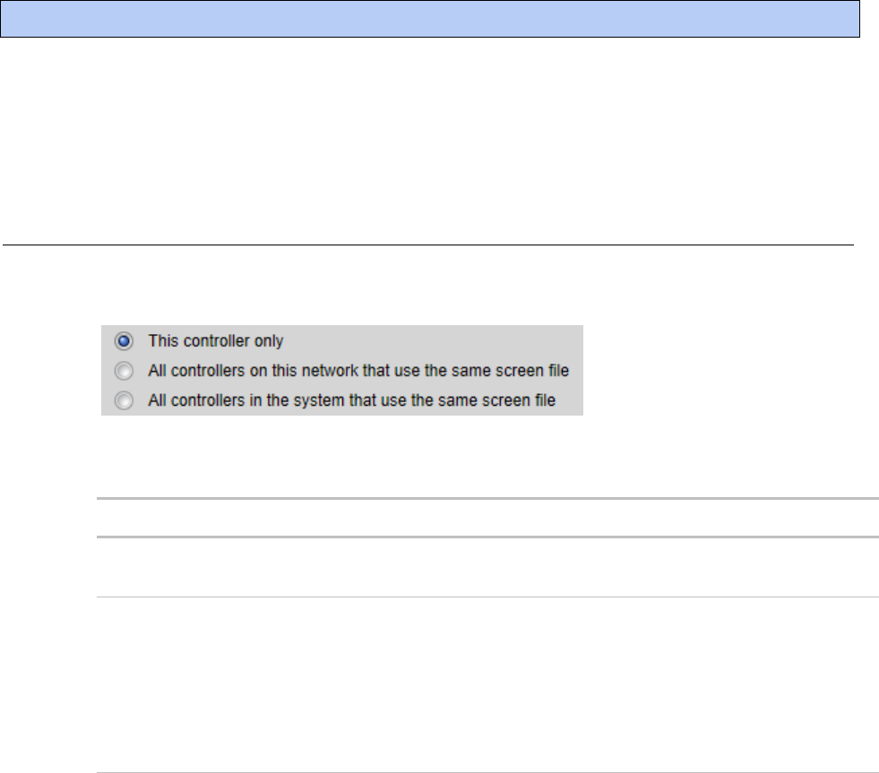
i-Vu Pro v7.0 Help CARRIER CORPORATION ©2020
All rights reserved
264
To use a touchscreen device or BACview® to view or edit a controller's property values, you must download a
screen file (.touch, .bacview, .S37, or.kpd) to the controller. The screen file is typically defined in SiteBuilder and
downloaded with the initial download to the controller, but you can select a different file in the i-Vu® Pro interface.
To select a different screen file
1 On the i-Vu® Pro navigation tree, right-click the controller, then select Driver Properties > Update tab.
2 If other controllers in the system use the current screen file, select which controllers you want to change.
3 Do one of the following:
If the screen file is...
In the Screen file drop-down list
a. Select the file.
b. Click Accept.
Not in the Screen file drop-down list
a. Click Add.
b. Browse to select the screen file.
c. Click Open.
d. Click Continue.
e. Click Close.
f. Click Close again.
4 Download All Content (page 257) to the controller.
NOTE You can click Delete Unused in the Screen File section to delete all unused screen files in:
i-Vu_Pro_x.x\webroot\<system_name>\views
i-Vu_Pro_x.x\webroot\<system_name>\programs
Working with touchscreen or BACview® files in the i-Vu® Pro interface

i-Vu Pro v7.0 Help CARRIER CORPORATION ©2020
All rights reserved
265
To edit a screen file on an i-Vu® Pro client
On an i-Vu® Pro client, you can get a copy of a screen file from the server, edit it, then put it back on the server.
To get the screen file
1 On the i-Vu® Pro navigation tree, right-click the controller that uses the screen file, then select Driver
Properties > Update tab.
2 Under Screen File, click Edit.
3 Click Save as.
4 Browse to the folder you want to put the file in.
5 Click Save.
6 Click Close.
To put the edited file back on the server
1 On the i-Vu® Pro navigation tree, right-click the controller that uses the screen file, then select Driver
Properties > Update tab.
2 Under Screen File, click Add.
3 Browse to select the file.
4 Click Open.
5 Click Continue.
6 Click Close.
7 Click Close again.

i-Vu Pro v7.0 Help CARRIER CORPORATION ©2020
All rights reserved
266
The i-Vu® Pro system can be viewed on the following client devices and web browsers.
Computers
The client computer should have at least:
• Dual core processor
• 1.5 GB RAM
• Communications link of 10 Mbps or higher
The i-Vu® Pro application will work with slower computers and slower links, but the results may not be satisfactory.
A computer with this
operating system...
Supports these web browsers...
Windows®
Google
TM
Chrome
TM
v66.0 or later
1
Internet Explorer® v11 Desktop
Microsoft® Edge v40 or later
Mozilla® Firefox® v60.0 or later
Mac® OS X®
(Apple® Mac only)
Safari® v11 or later
2
Google Chrome v66.0 or later
Mozilla Firefox v60.0 or later
1
Best performance
2
Best performance unless browser is running on a Mac® Mini or a MacBook:
WARNING If machine is running Mountain Lion 10.8x with an integrated Intel HD 400 graphics card,
it will experience display issues. Use one of these workarounds for better performance:
If an additional NVIDIA graphics card is available, manually switch the graphic card setting in MAC® OS
X® to use that card.
If not, use Google
TM
Chrome
TM
v66.0 or later.
Mobile devices
Device type
Platform support
Smart phone
Android
TM
, iOS
Tablet
Android
TM
, iOS, Surface
TM
NOTE Some functionality may be limited by the capability of the mobile device and operating system.
Setting up i-Vu® Pro client devices and web browsers

i-Vu Pro v7.0 Help CARRIER CORPORATION ©2020
All rights reserved
267
Setting up and using a computer with the i-Vu® Pro system
Set the monitor's screen resolution to a minimum of 1920 x 1080 with 32-bit color quality
You may want to disable the computer's navigation sounds.
Mac only
NOTE The instructions below are for a Mac OS X 10.8. Other versions may vary slightly. See your computer's Help if
necessary.
Computer settings
To change setting...
Enable right-clicking to see
right-click menus:
On a Mac
1 Select System Preferences > Mouse.
2 Click the drop-down list that points to the mouse's right-click button,
then select Secondary Button.
On a MacBook
1 Select System Preferences > Trackpad.
2 Enable Secondary click.
The instructions in Help are for a Windows computer. For instructions that include the Ctrl key, replace Ctrl with
Command. For example, replace Ctrl+click with Command+click.
Setting up and using a web browser to view the i-Vu® Pro interface
To set up and use Internet Explorer
NOTES
The instructions below are for Internet Explorer® 11. Other versions may vary slightly. See your web browser's
Help if necessary.
If the menu bar is not visible, right-click on the window's header, and then select Menu bar.
Web browser settings
To set in Internet Explorer...
Accept First-party and
Third-party cookies
Tools > Internet Options > Privacy > Advanced button
Automatically check for newer
versions of stored pages
Tools > Internet Options > General > Browsing history > Settings button

i-Vu Pro v7.0 Help CARRIER CORPORATION ©2020
All rights reserved
268
Web browser settings
To set in Internet Explorer...
Load ActiveX Control
Tools > Internet Options > Security > Custom Level button. Under
ActiveX controls and plug-ins, set the following:
Download signed ActiveX controls > Prompt
Download unsigned ActiveX controls > Disable
Run ActiveX controls and plug-ins > Enable
Script ActiveX controls marked safe for scripting > Enable
Select Play animations in web pages
Tools > Internet Options > Advanced > under Multimedia
Disable all the options on the Explorer
Bar
View > Explorer Bars
Disable web browser's pop-up
blockers
Tools > Pop-up Blocker > Turn Off Pop-Up Blocker
Disable external toolbar
pop-up blockers
Varies
Hide the web browser's toolbars
View > Toolbars
To...
Do the following...
Maximize the web browser window
Press F11 to turn full-screen mode on\off, or use the
minimize/maximize button in the top right corner of the browser window.
Have 2 different users logged in to
the i-Vu® Pro system on the same
computer
Start a new web browser session. Select File > New Session.
Clear browser cache
1 Select Tools > Internet Options.
2 Click Delete.
3 If you had the i-Vu® Pro system saved as a Favorite, uncheck
Preserve Favorites website data.
4 Click Delete again.
To set up and use Microsoft Edge
The instructions below are for Microsoft® Edge.
Web browser settings
To set in Microsoft Edge...
Do not block cookies
More Actions > Settings > View Advanced Settings > Cookies
Disable web browser's pop-up
blockers *
More Actions > Settings > View Advanced Settings > Block pop-ups

i-Vu Pro v7.0 Help CARRIER CORPORATION ©2020
All rights reserved
269
To...
Do the following...
Maximize the web browser window *
Use the minimize/maximize button in the top right corner of the browser
window.
Have 2 different users logged in to
the i-Vu® Pro system on the same
computer *
More Actions > New Window
Clear browser cache
More Actions > Settings > Clear browsing data > Clear
* Does not apply to Microsoft Edge on a phone.
To set up and use Mozilla Firefox
NOTES
The instructions below are for Mozilla® Firefox® v60.0 on a Windows operating system. Other versions may
vary slightly. See your web browser's Help if necessary.
If the menu bar is not visible, right-click on the window's title bar, and then select Menu bar.
If a message appears in the i-Vu® Pro interface that includes the checkbox Prevent this page from creating
additional dialogs, DO NOT check this box.
Web browser settings
To set in Firefox...
Disable Pop-up blocker
1 Click Tools > Options > Privacy & Security.
2 Under Permissions, click Exceptions next to Block pop-up windows.
3 Type http:// (or https://) and then the server name or IP
address of your system.
4 Click Allow and then Save Changes.
Enable JavaScript
1 In the address bar, type about:config, and then press Enter.
2 Click I accept the risk.
3 In the Search bar, type javascript.enabled.
4 If the value field shows true, JavaScript is enabled. If it shows false,
right-click javascript:enabled, and then select Toggle.
Add-ons Manager
Select Tools > Add-ons > Extensions. On this page, you can
enable/disable installed add-ons such as:
Adobe® Acrobat® Reader (to view PDF's)
QuickTime Plug-in (to play audible alarms)
Only installed Firefox add-ons will show up in the list.

i-Vu Pro v7.0 Help CARRIER CORPORATION ©2020
All rights reserved
270
To...
Do the following...
Maximize the web browser window
Press F11 to turn full-screen mode on\off.
Clear browser cache
1 Click Tools > Options > Privacy & Security.
2 Under Cookies and Site Data, click Clear Data.
3 Click Clear.
Have 2 different users logged in to
the i-Vu® Pro system on the same
computer
Start a new web browser session. Select File > New Private Window.
To set up and use Google Chrome
NOTES
The instructions below are for Google
TM
Chrome
TM
v66.0. Other versions may vary slightly. See your web
browser's Help if necessary.
If a message appears in the i-Vu® Pro interface that includes the checkbox Prevent this page from creating
additional dialogs, DO NOT check this box.
On a computer
Web browser settings
To set in Chrome...
Enable pop-ups
1 Click on the browser toolbar.
2 Select Settings.
3 Click Advanced at the bottom of the page.
4 Under Privacy and security, click Content settings.
5 Under Pop-ups > Allow, click ADD, and then type http:// (or
https://) and then the server name or IP address of your system.
To...
Do the following...
Clear browser cache
1 Click on the browser toolbar.
2 Select More tools > Clear browsing data.
3 Select a time range in the drop-down list.
4 Check the types of information that you want to remove.
5 Click CLEAR DATA.
Maximize the web browser window
Press F11 on your keyboard to turn full-screen mode on/off.

i-Vu Pro v7.0 Help CARRIER CORPORATION ©2020
All rights reserved
271
To...
Do the following...
Have 2 different users logged in to
the i-Vu® Pro system on the same
computer
Start a new web browser session. Click , then select New incognito
window.
On a Google Nexus
Web browser settings
In the Chrome menu...
Turn off desktop mode
Uncheck Request desktop site
Disable pop-up blocker
Settings > Advanced > Content Settings > uncheck Block
pop-ups
Enable JavaScript
Settings > Advanced > Content Settings > check Enable JavaScript
Enable Cookies
Settings > Advanced > Content Settings > check Accept Cookies
To...
In the Chrome menu...
Clear browser cache
Settings > Advanced > Privacy > CLEAR BROWSING DATA
To set up and use Safari
NOTES
The instructions below are for Safari® v11. Other versions may vary slightly. See your web browser's Help if
necessary.
We recommend that you do not run Safari in full-screen mode. If you do, i-Vu® Pro pop-ups will open full-
screen, covering the main application window.
On an Apple® computer (Mac®)
Web browser settings
To set in Safari...
Disable pop-up blocker
Preferences > Security > uncheck Block pop-up windows
Enable JavaScript
Preferences > Security > check Enable JavaScript
Enable Plug-ins
Preferences > Security > check Enable plug-ins
Prevent pop-ups from opening in a
new browser tab
Preferences > Tabs > uncheck Command-click opens a link in a new
tab
Prevent Safari from automatically
opening zip files exported from the i-
Vu® Pro application
Preferences > General > uncheck Open "safe" files after downloading

i-Vu Pro v7.0 Help CARRIER CORPORATION ©2020
All rights reserved
272
To...
Do the following...
Clear browser cache
History > Clear History
Have 2 different users logged in to
the i-Vu® Pro system on the same
computer
Start a new web browser session. Select Safari > Private Browsing >
File > New window
On an Apple® iPad
Web browser settings
To set on the iPad...
Disable pop-up blocker
Settings> Safari > set Block pop-ups to Off
Enable JavaScript
Settings > Safari > set JavaScript to On
To...
Do the following...
Clear browser cache
Settings > Safari > Clear History
On an Apple® iPhone 6
Web browser settings
To set on the iPad...
Enable JavaScript
Settings > Safari > Advanced

i-Vu Pro v7.0 Help CARRIER CORPORATION ©2020
All rights reserved
273
System Options provides administrative access for the following functions:
My Settings (page 273) - user's login, navigation tree preferences, and personal contact information
System Settings (page 274)
○ General (page 274)
○ Security (page 279)
○ Communications (page 280)
○ Scheduled Tasks (page 281)
○ Daylight Saving (page 282)
○ Add-ons (page 283)
Operators (page 149) - operator passwords, levels of access (roles), menu starting location
Privilege Sets (page 149)
Operator Groups (page 153)
Categories (page 51) - Schedule, Alarm, Graphic, Property, Trend, Report
Connections (page 179) - To set up a BACnet/IP connection in the i-Vu® Pro interface
Services (page 9)
License Administration (page 285)
Update (page 286)
Client Installs - download Sun's Java VM. See Setting up a computer (page 267) and Alarm Popup Application
(page 71) in the i-Vu® Pro Help.
My Settings
On the My Settings page, you can change settings, such as your:
Password
Viewing preferences
Contact information
NOTE The System Administrator can also change these settings on the Operators page.
Using System Options

i-Vu Pro v7.0 Help CARRIER CORPORATION ©2020
All rights reserved
274
To change your settings:
1 On the System Options tree, select My Settings.
2 Make changes on the Settings or Contact Info tab. See table below.
3 Click Accept.
Field
Notes
Change password
Enable this field, then type your current and new password and then confirm.
Limit is minimum of 8 and maximum 40 characters of any type.
Starting Location and
Starting Page
The i-Vu® Pro view, location, and page that will be displayed after you log in.
Automatically collapse trees
Expands only one tree branch at a time.
Automatically download
schedules on each change
Select to automatically download all new schedules that you create and
schedules that you change.
Play sound at browser when
server receives
Check Non-critical alarms or Critical alarms if you want the system to audibly
notify you when that type of alarm is received.
You can specify a different sound file.
• Internet Explorer, Firefox, and Safari support .wav, .mp3, or .au files.
• Google Chrome supports .wav or .mp3 files.
1 Put your file in the webroot\_common\lvl5\sounds folder.
2 In the Sound File field, replace normal_alarm.wav or critical_alarm.wav with
the name of your sound file.
NOTE You can put your sound file anywhere under the i-Vu_Pro_x.x folder, but
you must change the path in the Sound File field.
System Settings
The System Settings page contains information that you must enter before the i-Vu® Pro application can run
properly.
1 On the System Options tree, select System Settings.
2 Click each tab, then enter the necessary information. Tab details are described below.
General tab
The General tab presents the following System Information:
System Directory Name
Path to the Webroot Directory
Database Type
System Language

i-Vu Pro v7.0 Help CARRIER CORPORATION ©2020
All rights reserved
275
You can edit or use the following fields and buttons.
Field
Notes
System Information
System Statistics button
Click to see the following system information:
Number of controllers
Number of controllers that can run control programs
Number of points, regardless of vendor
Number of trend sources in database
Number of trend samples in database
Levels displayed in paths
The number of levels displayed in i-Vu® Pro paths. For example, if Node
Name Display Depth is set at:
2, a typical path might be ..\AHU-1\RA Temp
3, a typical path might be ..\Atlanta R&D\First Floor\AHU-1
NOTE Changing this field does not take effect until you restart the i-Vu
Pro Server application.
Use metric units for CCN tables and
control
Check to use metric values.
Logs
Select a week of logs to review
For troubleshooting, you can download a zip file that contains logs of
system activity.
Time
Time Format
Select one of the following for the system's time:
12-hour clock (Example: 4:34 pm)
24-hour clock (Example: 16:34)
Date Format
Select the format you want the system to use.

i-Vu Pro v7.0 Help CARRIER CORPORATION ©2020
All rights reserved
276
Field
Notes
Time Sync
Click to immediately synchronize the time on all IP network controllers in
the system database to the i-Vu® Pro server's time.
Check Enable time synchronization of controllers daily at____ to set daily
time synchronization occurs daily if the field on the Scheduled Tasks tab
(page 281) is enabled. (Click this link for more information on time
synchronization.)
Automatically synchronizes the time on all equipment to the time on the
server, adjusting for different time zones and Daylight Saving Time. We
recommend that you check this field.
The i-Vu® Pro application will send a daily time sync message to each IP
network device that is in the system database. IP devices not in the
database will not be synchronized. For all MS/TP networks in the
database, the i-Vu® Pro application will send a broadcast time sync
message. All devices on these networks will be synchronized, regardless
of whether or not the devices are in the database.
CAUTIONS
Make sure that your server’s time and time zone setting are correct.
To prevent time sync problems when the transition to and from
Daylight Saving Time occurs, set the time sync to occur at least 1
hour after the last controller in the system is adjusted for DST. For
example, your server and part of your system is in the Eastern
Standard Time zone, but you also have controllers in the Pacific Time
zone. Your server is adjusted for DST at 2:00 a.m. Eastern Standard
Time, but the controllers in the Pacific Time zone are not adjusted
until 3 hours later. So you would set the time sync to occur daily at
6:00 a.m. or later.
NOTES
You can perform system-wide time synchronizations using the Time
Sync button.
Between time sync broadcasts, Carrier routers include time sync
information in each color request to the devices below the router.
This ensures devices without a battery-backed clock will get the time
shortly after powering up.
Alarms
Enable support for Alarm
Notification Clients to connect to
this server
Check to use the Alarm Notification Client application. See Alarm Popup
(page 71) alarm action.
Schedules
Disable Schedules
If your system has no need to run schedules, check this box so that the
Schedules feature is no longer visible in the i-Vu® Pro interface.
Trends

i-Vu Pro v7.0 Help CARRIER CORPORATION ©2020
All rights reserved
277
Field
Notes
Keep trends for ___ days
Stores trend data in the i-Vu® Pro database for the time you specify. This
is a default setting that you can change when you set up trends for an
individual point.
Display gap in graph line for missing
data
Check to show a gap if trend data is missing.
Source Files
All Source Files
Use to export source files to a .zip file that can be imported into another i-
Vu® Pro or Field Assistant system. Source files include:
Control programs (.equipment files only)
Drivers
Graphics (.view files only)
Touchscreen files
BACview® files
Report design files for Equipment Values or Trend Sample reports
NOTE If import detects a difference between a database file and an
import file with the same name, import does not overwrite the database
file. A message lists any file differences so that you can resolve them. See
Commissioning equipment using Field Assistant (page 255).
Download
Optimize download for Open PIC
controllers
Check to increase download speed. The full source files are not
downloaded into the PIC controllers when this is checked.
Include graphics in Open
programmable controller download
Uncheck to increase download speed. If you are not changing the
graphics, you may not want to include them in every download.
Clippings

i-Vu Pro v7.0 Help CARRIER CORPORATION ©2020
All rights reserved
278
Field
Notes
Import
Click button to import clipping files, which include:
Navigation tree items including attached control programs, graphics,
drivers, and screen files
Trend data
Reports
Alarm categories
Schedules and schedule group membership (including the entire
schedule group and schedules, if it does not exist in the target
system)
Alarm actions
NOTES
Does not include operators or alarms
A clipping containing CCN controllers does not include the CCN
tables. When importing a clipping containing CCN devices, you must
re-scan the table.
Email Server Configuration
The information in this section is used by the Send email alarm action
(page 78) and used to email a Scheduled Report (page 140).
From
Enter a valid address if required by your mailserver.
Mail Host
The mailserver's address. This can be an IP address or a system name,
such as mail.mycompany.com.
Mail Host Port
Change this field if using a port other than the default port 25.
Mail Host Security Options
Select the type of security the mailserver uses.
Cleartext (SMTP) – Uses the SMTP protocol to send as clear text over
TCP/IP
Secure SSL (SMTP with SSL) – Uses SSL, a communication protocol
that provides data encryption
Secure TLS (STARTTLS) – Uses TLS, but does not begin encryption
until the i-Vu® Pro application issues STARTTLS command
Specify Mail User for Mail Host
Authentication
Select if your mailserver requires a username and password.
Test connection
Click to have the i-Vu® Pro application try to connect to the email server.
A message will appear below this button stating if the connection was
successful or if it failed.

i-Vu Pro v7.0 Help CARRIER CORPORATION ©2020
All rights reserved
279
Security tab
Field
Notes
Logging
Log audit data to file
Records operator activities and some system activities (such as opening and
closing the database or automatic deletions) in a text file.
The default file is auditlog.txt stored in i-Vu_Pro_\webroot\<system_name>.
You can change the file name and include a different path.
To prevent the file from growing too large as new data is appended, you can
archive the data to another text file by selecting an archive frequency in the
Archive log file contents field. The archive file is auditlog_yyyy_mm_dd.txt,
where yyyy_mm_dd is the creation date of the archive file. This file is
created in the same location as auditlog.txt.
NOTE If you do not archive the log file contents, you should manually delete
the oldest entries.
Log audit data to database
Records audit data in a database named audit.mdb that can be accessed by
third-party software.
NOTE For Access, MSDE, and Derby, the database is automatically created.
An Access database is named audit.mdb; a MSDE database is named
audit.mdf. The Derby database consists of multiple files in a folder called
audit. For MySQL, SQL Server, or PostgreSQL, you must create the database
manually.
Delete database entries older
than ____ days
Automatically deletes entries in the database that are older than the number
of days you specify.
Log errors for invalid URLs
Check this field to write to the core.txt log any time an external source sends
a request to the i-Vu® Pro Server application.
NOTE Regular maintenance scans by external software can cause the log
files to grow large.
Security Policy
Change Policy
See Location-dependent operator access (page 157) for information on
Change Policy.
Remote Access
Allow remote file management
Lets you access the system using WebDAV.
Operators
Return operators to previous
locations when server
reconnects
Returns operators to current tree locations when the server reconnects.
Log off operators after _:_
(HH:MM) of inactivity
The system automatically logs off an operator who has had no activity in the
system for the time period specified.
This is a default setting for the system. The System Administrator can change
this setting for an individual operator on the Operators page.

i-Vu Pro v7.0 Help CARRIER CORPORATION ©2020
All rights reserved
280
Field
Notes
Lock out operators for __
minutes after __ failed login
attempts
Clear Lockouts removes lockouts for all users.
NOTE Restarting the i-Vu® Pro Server application will remove lockouts.
Use advanced password policy
You can place specific requirements on passwords to increase security. See
Advanced password policy (page 162).
Permissions
Permissions
When control programs, views, touchscreen, and BACview® files are created
by an original equipment manufacturer (OEM), they cannot be used in the i-
Vu® Pro system without the creator's permission. However, the creator can
produce a key for a system with a different license that will grant permission
to the key's recipient.
If you receive a key, put it in the i-Vu_Pro_ x.x\resources\keys folder. The
table in the Permissions section of the Security page shows all keys in the
that folder. To activate a key, click Add, then browse to the key.
To delete a key from your system, select the key in the table, then click
Delete.
Red text in the table indicates the key has a problem such as it does not
apply or has expired. See the Notes column for an explanation.
Communications tab
The fields on this tab let you define controller communication with the i-Vu® Pro Server application and BACnet
network communication.
Field
Notes
i-Vu Pro Server BACnet
Controller Instance
and
BACnet Alarm Recipient
Instance
The BACnet identifier for the system's server and the alarm recipient. You
enter these system properties in SiteBuilder.
Always upload properties from
controllers to i-Vu Pro database
on mismatch
Automatic uploads are listed in the Audit Log.
If you do not check this field, properties must be manually uploaded or
downloaded by the operator when a mismatch occurs.
NOTE If an automatic upload fails and the operator chooses to do nothing at
that time, the upload will be attempted again when he returns to the page
where he encountered the mismatch.
Ignore incoming alarms from
sources not in this database
The i-Vu® Pro application will ignore alarms from third-party devices not in
the database or devices from other i-Vu® Pro systems on the same network.
BACnet Settings
Native i-Vu® Pro system only

i-Vu Pro v7.0 Help CARRIER CORPORATION ©2020
All rights reserved
281
Log BACnet Binding Conflicts
The i-Vu® Pro application uses BACnet (dynamic) binding for communication
between devices unless your system uses NAT routing. If using NAT, the i-
Vu® Pro application uses information in its database to bind to BACnet
devices.
When checked, the i-Vu® Pro application logs binding conflicts that result
from duplicate network numbers or device IDs.
Scheduled Tasks tab
Field
Notes
Automatically delete alarm
incident groups which have been
closed for more than ___ days
An incident group is all alarms related to a particular incident, such as Off
Normal, Fault, and Return to Normal. You can edit this on the Devices >
Advanced tab.
NOTE Alarms in an incident group are not deleted until all alarms in the
group have been closed.
Archive alarm information upon
alarm deletion
Writes alarm information to a text file.
Automatically delete expired
schedules daily at ___
To ensure there are no time zone conflicts, the i-Vu® Pro application waits 2
days after a schedule expires to delete it.
Remove expired historical
trends daily at ____
Deletes trend data that has been in the database longer than the time
specified in the Keep historical trends for ___ days field on the General tab.

i-Vu Pro v7.0 Help CARRIER CORPORATION ©2020
All rights reserved
282
Field
Notes
Enable time synchronization of
controllers daily at____
Automatically synchronizes the time on all equipment to the time on the
server, adjusting for different time zones and Daylight Saving Time. We
recommend that you check this field.
The i-Vu® Pro application will send a daily time sync message to each IP
network device that is in the system database. IP devices not in the database
will not be synchronized. For all MS/TP networks in the database, the i-Vu®
Pro application will send a broadcast time sync message. All devices on
these networks will be synchronized, regardless of whether or not the
devices are in the database.
CAUTIONS
Make sure that your server’s time and time zone setting are correct.
Make sure that each site’s time zone setting in SiteBuilder is correct.
To prevent time sync problems when the transition to and from Daylight
Saving Time occurs, set the time sync to occur at least 1 hour after the
last controller in the system is adjusted for DST. For example, your server
and part of your system is in the Eastern Standard Time zone, but you
also have controllers in the Pacific Time zone. Your server is adjusted for
DST at 2:00 a.m. Eastern Standard Time, but the controllers in the
Pacific Time zone are not adjusted until 3 hours later. So you would set
the time sync to occur daily at 6:00 a.m. or later.
NOTES
You can perform system-wide time synchronizations using the Time Sync
button on the General tab (page 274).
Between time sync broadcasts, Carrier routers include time sync
information in each color request to the devices below the router. This
ensures devices without a battery-backed clock will get the time shortly
after powering up.
Daylight Saving tab
On this tab, you can adjust the Daylight Saving Time settings.
Click Update to automatically set the table's Begin and End dates for the next 10 years based on the system's
timezone. This marks all controllers for a Parameters download.
If the updated dates are incorrect
If you clicked Update but the dates are incorrect, your system's Java timezone data may be out-of-date. Do the
following:
1 Go to the Oracle Java SE Download site (http://java.sun.com/javase/downloads).
2 Download the JDK DST Timezone Update Tool (tzupdater-version.zip) and unzip the file. The zip file contains
2 items:
○ tzdata.tar.gz
○ tzupdater.jar

i-Vu Pro v7.0 Help CARRIER CORPORATION ©2020
All rights reserved
283
3 In the i-Vu® Pro interface, click , then select System Options > Daylight Saving and then click Import.
4 Browse to the tzupdater.jar file, select it, then click Open.
5 Click Continue. This restarts the i-Vu® Pro application.
6 After the restart, in the i-Vu® Pro interface, click , then select System Options > Daylight Saving and
then click Import.
7 Browse to the tzdata.tar.gz file, select it, and then click Open.
8 Click Continue. This restarts the i-Vu® Pro application.
9 On the System Options > Daylight Saving tab, click Update.
Add-ons tab
The i-Vu® Pro system supports add-ons, such as Tenant Billing, that retrieve and use the i-Vu® Pro data.
Some add-ons have been updated for compatibility with the i-Vu® Pro v7.0 application . Be sure that you have the
latest version of the add-ons that were used in the previous i-Vu® Pro version.
By default, the i-Vu® Pro application allows only signed add-ons that have been approved by Carrier. If needed, you
can override this setting in SiteBuilder by going to Configure > Preferences > Web Server, and checking Allow
unsigned add-ons. However, unsigned add-ons are not supported.
To install an add-on
1 Save the add-on's file (.addon or .war) to your computer.
2 On the System Options > System Settings > Add-ons tab, click Browse, and then open the file.
3 Click Install Add-on. After a few seconds, the add-on will appear in the Installed table, and will be enabled. The
table below gives a description of each column.
Column
Notes
Name
The add-on's name.
Path
To open the add-on in a web browser, append this path to your i-Vu® Pro
system's address.
For example, to start Tenant Billing, enter
http://<system_name>/override, or
http://<system_IP_address>/override
Version
The version is shown if the author provided the information in the add-on.
Status
If this column shows:
○ Running, you can open the add-on in a web browser.
○ Disabled, click Enable to run the add-on.
○ Startup error, select the table row to see an explanation of
the error under Details.

i-Vu Pro v7.0 Help CARRIER CORPORATION ©2020
All rights reserved
284
1 Select an add-on in the Installed table to disable or enable it, or to see the following Details.
Add-on
main page
Click the main page link to open the add-on, if the author provided a main
page.
Description
A description of the add-on, if the author provided one
Vendor Name
The add-on's author
Public Data Directory
This public directory contains data generated by the add-on. This data is
visible in a web browser.
Private Data Directory
This private directory contains information such as configuration data.
To back up the add-on's private and public data directories
NOTE This procedure will not back up data stored in an external database.
1 Select the add-on in the table.
2 Click Save Data.
3 Click OK.
4 Click Save.
5 Select the location where you want to save the data, then click Save.
To update an add-on
NOTE Add-ons for i-Vu® Pro v6.0 or later systems have a different folder structure than previous versions.
1 Select the add-on in the table.
2 Click Remove Add-on and Keep Data
3 Follow the procedure above to install the new version of the add-on.
To uninstall an add-on
1 Select the add-on in the table.
2 Click Remove Add-on and Data.

i-Vu Pro v7.0 Help CARRIER CORPORATION ©2020
All rights reserved
285
To register and download your i-Vu® Pro license
To register your software, you must obtain a license from Carrier and then apply it in the i-Vu® Pro interface.
1 Login to i-Vu Systems website (http://accounts.ivusystems.com).
NOTES
○ Only Carrier authorized personnel may access the website. To set up your account, please contact
Controls Support with the following information: name, phone number, e-mail address, office address,
and your password of choice.
○ If you are an end-user or contractor, please contact your local Carrier office to obtain your license.
2 Select Register/Download i-Vu Software Licenses.
3 Expand the applicable section under Available Licenses and select the site/project to register it.
NOTE All your Sites Names/Project Names are listed.
4 In License Details, fill in the Owner and Site information and click Register License.
5 Check I agree to the terms of use.
6 Click Download License and then save the .properties file to a convenient location to use when installing the i-
Vu® Pro application.
To apply the license to the i-Vu® Pro application
During the i-Vu® Pro installation, in the Setup Wizard, on the Product License screen, check Browse to a different
license, and select the site license you obtained.
NOTES
○ Selecting the default license results in a prompt appearing every few minutes in the i-Vu® Pro interface to
remind you to apply your site license.
○ Do not edit any part of this registered license file. Editing a license file invalidates the license.
○ Store the license in a safe location.
To apply the site license after the installation:
1 In the i-Vu® Prointerface, select System Options > License Administration.
2 Browse to the license file.
3 Click Apply.
4 Restart i-Vu® Pro Server using the rebootserver manual command (page 163).

i-Vu Pro v7.0 Help CARRIER CORPORATION ©2020
All rights reserved
286
Update
In System Options on the Update tab, click the Update button to install .update files (patches, service packs,
drivers, language packs, graphics libraries, and help updates).
See below for details on updating the SAL library and applying it to your system.
Update the SAL library
The i-Vu® Pro SAL files update youri-Vu® Pro controllers. The SAL libraries contain control programs, graphics,
drivers, screen files, and other important controller data.
Carrier periodically provides updates, which include enhancements and bug fixes.
NOTES
The library update only changes default graphics. If you have edited your graphic in ViewBuilder, it is not
updated.
The last digits in the SAL library name are the release date of the library.
All of the SAL files will not necessarily have the same <date> revision.
To ensure that your installation is running the latest software, we recommend that you check Control Systems
Support http://www.hvacpartners.com/, https://accounts.ivusystems.com/ for updates. Download the latest
SAL files and apply them to all new installations.
If you are changing to an older SAL file than the current one being used, a warning asks you if you are sure you
want to apply an older version.
NOTE Keep copies of the latest libraries in a safe place. In the event of a system restore, the updated .sal file must
be reapplied.
To check current SAL library version
1 Login to the i-Vu® Pro application.
2 Click , then select System Options > Update tab.
3 Click Current Libraries (.sal) to view the current SAL libraries and their revision date.
Step 1: Update library
1 Save the updated library (.sal file) to your computer.
2 Click , then select System Options > Update tab.
NOTE Expand Current Libraries (.sal) to see the current SAL libraries and their revision. Compare them to
what you downloaded from the Control Systems Support to determine if any of them have been updated.
3 Click and browse to the updated .sal file that you have saved on your computer, select the file,
and click Open.
4 Click Continue.

i-Vu Pro v7.0 Help CARRIER CORPORATION ©2020
All rights reserved
287
5 When process is complete, the message appears File added successfully.
6 Click Close.
NOTE These changes are not applied to the controllers until you have updated routers and controllers.
Follow these steps to implement the new equipment library:
Step 2: Update the files for the routers
1 Select the router that you wish to update in the navigation tree.
2 Right-click and select Driver Properties.
3 Select Properties page > Update tab.
4 If the database contains two or more routers, you must check Change for all controllers of this type? in the
Controller section.
5 Click Update. A message appears Changes the driver and screen file to use the current library version.
Continue?
NOTE If more than one router exists, the additional routers are listed below the Update button.
6 Click OK.
7 Click Accept.
Step 3: Update the files for the controllers
1 Double-click the controller in the navigation tree or right-click and select Configure.
2 If you have multiple controllers of the same type, enable Change for all control programs of this type?.
3 Click Update under Control Program. A message appears Changes the control program, view, driver, and
screen file to use the current library version. Continue?
4 Click OK. When the message Updated to the library version xx. appears, click Close.
5 Repeat steps 1 - 4 for any additional types of controllers.
6 Click Close again.
Step 4: Update the files for CCN controllers
1 In the navigation tree, select the CCN device manager associated with the controllers that are to be updated.
2 Select Devices > CCN Discovery and re-scan any controllers that need to be updated by checking Rescan
Controllers Selected Below for Configuration Changes and clicking Start Scan.
Step 5: Apply the update to the routers and controllers
1 Select the System in the navigation tree and then select the Downloads page.
2 If you wish to apply the new SAL file to your entire system, you can use this page to compare to your
navigation tree and verify that you have selected all of your routers and controllers for download.
NOTE Only the CCN Gateway and device managers require download, so the CCN controllers/equipment will
not be listed.
i-Vu Pro v7.0 Help CARRIER CORPORATION ©2020
All rights reserved
288
3 A network's controllers download in the order shown. To change the order, select a controller(s), then drag and
drop or click Move to Top or Move to Bottom.
EXCEPTION If a controller's router requires a download, it will download first regardless of its position on the
Downloads page. Click the Start button.
NOTES
○ Use Ctrl+click, Shift+click, or the Select All checkbox to select multiple controllers.
○ See To download from the Downloads page (page 258) in Help for more details.
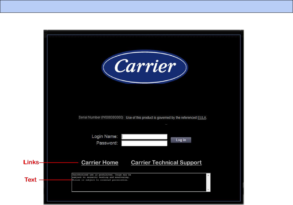
i-Vu Pro v7.0 Help CARRIER CORPORATION ©2020
All rights reserved
289
You can add links or text, such as a disclaimer, to i-Vu® Pro's login page.
Adding links or text to i-Vu® Pro's login page
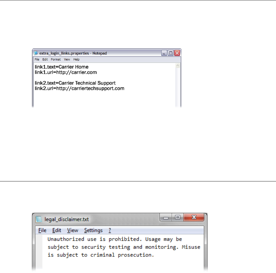
i-Vu Pro v7.0 Help CARRIER CORPORATION ©2020
All rights reserved
290
To add links to the login page
1 In a text editor such as Notepad, type 2 lines for each link that you want on the login page.
Line 1: link#.text=<the link text that is to appear on the login page>
Line 2: link#.url=<the link's address>
Example to add links shown above:
2 Save the file with the following name and location.
File name: extra_login_links.properties
Location: ivu_pro_x.x\webroot\<system_name>
To add text to the login page
1 In a text editor such as Notepad, type the text that you want on the login page.
Example to add text shown above:
2 Save the file with the following name and location.
File name: legal_disclaimer.txt
Location: ivu_pro_x.x\webroot\<system_name>

i-Vu Pro v7.0 Help CARRIER CORPORATION ©2020
All rights reserved
291
To import a clipping
You can export a clipping (a portion of a system) in SiteBuilder and then import it in the i-Vu® Pro interface. The
following items are imported:
One or more selected tree items including attached control programs, graphics, and drivers
Reports
Alarm categories
Location-dependent security information
Schedules and schedule group membership (including the entire schedule group and schedules, if it does not
exist in the target system)
Alarm actions
Source tree relationships (including source tree rules if the source tree does not exist in the target system)
To import a clipping:
1 Click , then select System Options > System Settings.
2 On the General tab, click Clippings. and then .
3 Browse to and select the clipping you want to import, then click Next.
4 Optional: If necessary, you can change the location path where the clipping will be imported. Select the
system fragment, then select the import location in the tree below.
5 Click Next.
6 If asked if you want to overwrite components, follow the on-screen instructions.
7 The interface shows any conflicts and problems that were found during the import. Make any needed
corrections in SiteBuilder.
NOTE Click Copy to Clipboard and then paste the list into another program such as Notepad for viewing or
printing.
8 Click Next.
9 Click Finish.
Editing a system remotely

i-Vu Pro v7.0 Help CARRIER CORPORATION ©2020
All rights reserved
292
10 Do any of the following that apply.
If you imported...
Do the following in the SiteBuilder
application...
Do the following in the i-Vu® Pro
application...
Another site into the system
Change the new site's BACnet/IP
network number to be the same as the
other BACnet/IP network(s).
Download All Content to all Carrier IP
routers in the system.
A second BACnet/IP network
into a site
Move the items under the new network
to the original BACnet/IP network, then
delete the new network.
Download Parameters to any
controllers that you moved.
Any controllers that use the
SiteBuilder option Automatically
Configure My BBMDs
N/A
Download BBMDs to the routers.
Any controllers that use
manually configured BBMD
tables
N/A
Update the routers' BBMD tables.
See "To set up BBMDs through the i-
Vu® Pro interface (page 184)"
or
"To set up BBMDs using the BBMD
Configuration Tool (page 186)"
in i-Vu® Pro Help.
A clipping without trends into a
system using NAT
N/A
Restart IP connection(s) to new
devices.
Managing files on a remote i-Vu® Pro server
The i-Vu® Pro application supports WebDAV, a network protocol designed for managing remote server files through
an Internet connection. Use a third-party WebDAV client application, such as WebDrive, to access the Internet from
anywhere in the world and manage your system files residing on a distant i-Vu® Pro server.

i-Vu Pro v7.0 Help CARRIER CORPORATION ©2020
All rights reserved
293
Running i-Vu Pro Server without connecting to controllers
To verify links between graphics and to set up properties, schedules, alarms, and trends before you connect to the
network, run i-Vu Pro Design Server instead of i-Vu Pro Server. Then view the i-Vu® Pro interface in a web browser.
NOTE Question marks indicate correct microblock paths. Missing data indicates errors.
Switching i-Vu Pro Server to a different system
Design engineers working on multiple projects can switch systems in the i-Vu Pro Server application.
1 In the i-Vu Pro Server application, select Server > Change Active System.
2 Select a different system (it must be in the webroot folder) and mode.
3 Click Select.
Running i-Vu Pro Server as a Windows® service
For Windows 7, 8, 10, 2008, 2012, and Vista
Run i-Vu Pro Server as a Windows service if you want i-Vu Pro Server to automatically start up when the server
computer is restarted.
NOTE If your i-Vu® Pro system uses a database other than Derby and the database is located on the same
computer as i-Vu Pro Server, you must set up Windows to delay starting i-Vu Pro Server until the database service
has started. See "How to delay loading of specific services" (http://support.microsoft.com/kb/193888) on the
Microsoft® website.
Options for running the i-Vu® Pro system
i-Vu Pro v7.0 Help CARRIER CORPORATION ©2020
All rights reserved
294
To install i-Vu® Pro Server service
NOTE If you are not sure if the service was previously installed, see To determine if i-Vu Pro Server service is
installed (page 296).
1 In the Windows Start menu, select All Programs > Accessories.
2 Right-click Command Prompt, then select Run as administrator.
3 Select Yes in the User Account Control message.
4 In the Command Prompt window, type: cd <path to the i-Vu Pro install directory>
For example, type: cd c:\i-Vu_Pro_x.x
replacing x.x with your current version number.
5 Press Enter.
6 Type: "i-Vu Pro Service.exe"
7 Press Enter.
To start i-Vu® Pro Server as a Windows service
1 In the Windows Start menu, select Control Panel.
2 Select Administrative Tools, then double-click Services.
3 In the Services (Local) list, double-click i-Vu Pro Service X.X.
4 In the Startup type drop-down list, select Automatic.
5 On the Log On tab, do one of the following:
○ For Windows Vista, 2008, 2010, and 2012, select This account, and then browse to select a user who is
a member of the Administrator Group on that computer.
○ For Windows 7 and 8, select Local System account.
6 Optional: If you selected Local System account in step 5 and you want to be able to access i-Vu Pro Server on
the server computer's desktop, check Allow service to interact with desktop.
NOTES
○ If you do not check this field, the computer screen will give no indication that i-Vu Pro Server is running;
you must view the computer's Services page to see if it is running.
○ This checkbox applies only to a user logged in on the server. A Windows Remote Desktop user cannot
access i-Vu Pro Server running as a service.
○ If you check this field, you cannot use the instructions below to set up printing to a network printer. Ask
your Network Administrator to set up Local System account to use a network printer.
○ If you check this field and the i-Vu® Pro application is to run email alarm actions, ask your Network
Administrator to set up Local System account to send emails.
7 On the General tab, click Start.
8 Click OK.
NOTE If i-Vu Pro Server does not start after you click Start, you may have a Windows permissions problem. Follow
the procedure below in To set up the i-Vu Pro service for network printing (page 295) to set up the Windows user
name and password.
i-Vu Pro v7.0 Help CARRIER CORPORATION ©2020
All rights reserved
295
To set up the service for network printing
If i-Vu Pro Server runs as a service on a computer that is using a network printer, you must set up the Windows
user name and password for the service. The Print alarm action requires this setup to be able to print.
1 In the Windows Start menu, select Control Panel.
2 Select Administrative Tools > Services.
3 Double-click i-Vu Pro Service x.x.
4 On the Log On tab, select This account.
5 Browse to the computer's domain, then select the user that the service will log in as.
NOTE Contact your network administrator if you need help determining the domain.
6 Type the user's password in the Password and Confirm password fields.
To stop or uninstall i-Vu® Pro Server service
To stop i-Vu Pro Server service
1 In the Windows Start menu, select Control Panel.
2 Select Administrative Tools, then double-click Services.
3 In the Services (Local) list, double-click i-Vu Pro Service X.X (where x.x is the i-Vu Pro version number.
4 In the i-Vu Pro Service x.x Properties dialog box, click Stop on the General tab.
5 Click OK.
To uninstall i-Vu Pro Server service
1 In the Windows Start menu, right-click Command Prompt, then select Run as administrator.
2 Select Yes in the User Account Control message.
3 In the Command Prompt window, type: cd <path to the i-Vu Pro install directory>
For example, type: cd c:\i-Vu_Pro_x.x
4 Press Enter.
5 Type: "i-Vu Pro Service.exe" -remove
6 Press Enter.
i-Vu Pro v7.0 Help CARRIER CORPORATION ©2020
All rights reserved
296
To determine if i-Vu® Pro Server service is installed
If you do not know if the service was previously installed, follow the appropriate steps below.
1 In the Windows Start menu, right-click Command Prompt, then select Run as administrator.
2 Select Yes in the User Account Control message.
3 In the Command Prompt window, type: cd <path to the i-Vu Pro install directory>
For example, type: cd c:\i-Vu Prox.x
4 Press Enter.
5 Type: "i-Vu Pro Service.exe" -check
6 Press Enter.

i-Vu Pro v7.0 Help CARRIER CORPORATION ©2020
All rights reserved
297
English is the i-Vu® Pro default language, but you can set up your system to display a different language. You can
also set up multiple languages so different operators can view the system in different languages.
Follow the procedures below to display the i-Vu® Pro interface in non-English languages.
1 Install a language pack (page 299).
2 Prepare your workstation for non-English text (page 297).
3 Create control programs and translation files (page 299).
4 Create graphics (page 302).
5 Create your system in SiteBuilder (page 304).
6 Set an operator’s language in the i-Vu® Pro interface (page 305).
Preparing your workstation for non-English text
NOTE The instructions below are for a Windows XP operating system. If you have a different operating system, see
your system's Help for instructions.
Set up your workstation so you can type international characters in control programs, graphics, or SiteBuilder.
1 Install the appropriate fonts for the languages you will be using. In the Windows Control Panel, open Fonts,
select File > Install new fonts.
2 In the Control Panel, open Regional and Language Options, then select the Input language.
Setting up a system for non-English languages

i-Vu Pro v7.0 Help CARRIER CORPORATION ©2020
All rights reserved
298
3 Install an Input Method Editor (IME) for non-alphanumeric characters.
See your operating system's Help for more information.

i-Vu Pro v7.0 Help CARRIER CORPORATION ©2020
All rights reserved
299
Installing a language pack
A language pack translates the text in the i-Vu® Pro interface. i-Vu® Pro is installed with an English language pack.
To download other language packs, obtain them from the Carrier Control Systems Support Site
http://www.hvacpartners.com/, https://accounts.ivusystems.com/.
NOTE If you create a system by copying an existing system that uses language packs, install the same language
packs on the new system.
Creating control programs and translation files for a non-English system
To have the i-Vu® Pro interface display a control program’s user-defined text (such as microblock names and
property text) in a non-English language, you must:
1 Create the control program using key terms instead of the text.
2 Create translation files of key terms and their language-specific equivalents.
In the i-Vu® Pro interface, the key term is replaced with its equivalent in the translation file for the current operator
language. If a Properties page, Logic page, shows ??key term??, the key term is missing from the translation file.
NOTE To edit existing control programs or translation files, see Editing translation files, control programs (page
305).
To enter a key term in the Snap application
In the Snap Property Editor, type @ before each key term.
NOTES
Type only the key term in the Snap application. Expressions such as $present_value$ are put in the
translation file as part of the translated text. See EXAMPLES in "Translation files" below.
Key terms can contain only alphanumeric characters and underscores (no spaces) and cannot start with a
number.

i-Vu Pro v7.0 Help CARRIER CORPORATION ©2020
All rights reserved
300
Translation files
Translation files are used to translate key terms in control programs. A translation file contains key terms and their
language-specific equivalents.
For a non-English system, you must create an English translation file and a non-English translation file* for each of
the following:
Each control program
Key terms used in multiple control programs
EXAMPLES
Translation files
Key term=Language-specific equivalent
English
This_value=This value is $present_value$
Zone_temp=Zone temperature
Spanish
This_value=Este valor es $present_value$
Zone_temp=Temperatura de zona
*If the i-Vu® Pro interface will display multiple non-English languages, create a translation file for each language.
To create and implement a translation file
Create your translation file in a text editor, such as Microsoft® Word, that supports the character encoding you
need.
1 Type one key term and language equivalent per line, left justified, starting in column 1. Do not put spaces on
either side of the equal sign.
2 Save the file using the appropriate file name and location in the table below.
If key terms are used in...
the file name is...
File location
A single control program
<any_name>_xx.native*
Any location
Multiple control programs
equipment_xx.native*
i-Vu_Pro_\webroot\
<system_name>\resources
* xx = the language extension code. See "Extension codes and encoding" below.
If you are using:
○ the English character set, save the file as Text only.
○ a non-English character set, save the file as Encoded text . (See your application’s help for information on
saving files as encoded text.) When prompted for the language and encoding, see “Extension codes and
encoding” below.
3 Open the control program in the Snap application, then select Control Program > Bundled Resources.

i-Vu Pro v7.0 Help CARRIER CORPORATION ©2020
All rights reserved
301
4 Click , locate and select the translation file(s) for this control program, then click Open.
NOTES
○ Do not add equipment_xx.native files that you created for multiple control programs.
○ You can use Ctrl+click or Shift+click to select multiple files.
5 Save the control program. The translation files are embedded in the control program; the original files are no
longer necessary.
Extension codes and encoding
Language
Extension codes
Encoding*
Brazillian Portuguese
English
Canadian French
French
German
Italian
Japanese
Korean
Russian
Spanish
Swedish
Simplified Chinese
Traditional Chinese
Thai
Vietnamese
pt_BR
en
fr
fr_FR
de
it
ja
ko
ru
es
sv
zh
zh_TW
th
vi
ISO-8859-1
ISO-8859-1
ISO-8859-1
ISO-8859-1
ISO-8859-1
ISO-8859-1
EUC-JP
EUC-KR
KOI8_R
ISO-8859-1
ISO-8859-1
GB2312
Big5
TIS620
Cp1258
* Encoding is used when you create the translation file.

i-Vu Pro v7.0 Help CARRIER CORPORATION ©2020
All rights reserved
302
Creating graphics for a non-English system
To create a non-English graphic in ViewBuilder:
1 Set the language font (page 302).
2 Create the graphic. (page 302)
3 Save the .view file.
NOTE The names of your .view file and any inserted image files must contain only ASCII characters.
Setting the language font
If your system has language packs installed, you can select a font for each language. Your selection affects only
how text in your graphic appears in ViewBuilder.
To set the font for each language
1 Select Configure > Preferences > Graphic (.view).
2 On the Language tab, check the language that you want to be the default for all new graphics.
To select the default language font for all new graphics
In the Preview Font column, click the font name to select a different font.
To select the active language when creating a view
If you will use multiple language fonts in a single view, you can switch to a different language font as follows:
1 Select Configure > View Properties.
2 In the Language field, select the language you want to use.
3 Click OK.
To create a Non-English graphic
The method you use to create a graphic that will be displayed in a non-English i-Vu® Pro system depends on the
following:
If the i-Vu® Pro system will display only a single non-English language, create the graphic in that language.
If the i-Vu® Pro system will display multiple non-English languages, use either of the following methods:
○ Create the graphic in layers (one layer for each language), and then assign a show/hide conditional
expression (see format below) to each layer so that it displays in i-Vu® Pro based on the operator
language. See "To show/hide a layer in the i-Vu® Pro interface" in ViewBuilder Help.

i-Vu Pro v7.0 Help CARRIER CORPORATION ©2020
All rights reserved
303
○ Create each piece of the graphic in the different languages, and then assign a show/hide conditional
expression (see format below) to each piece so that it displays in i-Vu® Pro based on the operator
language. See "Setting objects on a graphic to show/hide in the i-Vu® Pro interface" in ViewBuilder Help.
Show/Hide conditional expression format
$$operator_language$$='language'
where language is the language code from the list below.
For example, the conditional expression to display French would be:
$$operator_language$$=='fr_FR'
Language
Language code
Brazillian Portuguese
English
Canadian French
French
German
Italian
Japanese
Korean
Russian
Spanish
Swedish
Simplified Chinese
Traditional Chinese
Thai
Vietnamese
pt_BR
en
fr
fr_FR
de
it
ja
ko
ru
es
sv
zh
zh_TW
th
vi

i-Vu Pro v7.0 Help CARRIER CORPORATION ©2020
All rights reserved
304
Creating a non-English system in SiteBuilder
To choose the language(s) for your system
1 In SiteBuilder, select Configure > Preferences.
2 Select the Language tab.
3 Under Supported Languages, select each language that you want to be available in your system.
NOTE This list shows all installed language packs. To install additional languages, see Installing a language
pack (page 299).
4 In the System field, select the system Language (page 305).
5 Click OK.
6 Save your database.
To create your system
To create your system in each language that the system will display:
1 In SiteBuilder, select Configure > Preferences.
2 Optional: The Font tab shows the font that will be displayed in SiteBuilder for each language that you selected
on the Language tab. To change a font, click on the name in the Preview Font column, then make a new
selection.
3 On the Language tab, select a language in the Current Session field.
4 Click OK.
5 Create your system.
6 Save your database.
7 If your system will display multiple languages:
a) Select Configure > Preferences, select the Language tab, and select another language in the Current
Session field.
b) Re-enter all node names and display names in the current language.
c) Save your database.
d) Repeat steps a. through c. for each additional language the system will display.

i-Vu Pro v7.0 Help CARRIER CORPORATION ©2020
All rights reserved
305
System language
The system language is used for:
The default language for new operators
Alarms sent to the database
State text and object names downloaded to the field
The default login page *
All other information is displayed in the operator’s language, which may be different than the system language. See
To set an operator’s language in the i-Vu® Pro interface (page 305).
* You can change the language shown on the i-Vu® Pro login page by selecting a different language from the list
below the Password field.
To set an operator’s language in the i-Vu® Pro interface
An operator can change their language preference in the i-Vu® Pro interface.
1 On the System Options tree, select My Settings.
2 Under Preferences, select the Language in the drop-down list.
3 Click Accept.
Editing translation files or control programs for a non-English system
If you add or edit a key term in a control program, be sure to make the same change in the translation file. See
Creating control programs and translation files (page 299).
If you make changes after attaching a control program in SiteBuilder, do one of the following:
If you changed text only in a control program or its translation file, right-click the control program on the
Geographic tree, then select Rebuild Equipment Pages.
If you changed logic in the control program, right-click the control program on the Geographic tree, then select
Reload Control Program.
To edit a bundled resource
The Snap application bundles (embeds) the translation file(s) for a control program into the .equipment file. See
steps 3 through 5 in To create and implement a translation file (page 300). To edit a bundled translation file:
1 Open the control program in the Snap application.
2 Select Control Program > Bundled Resources.
3 Select the file, then click to save it to your hard drive.
4 Edit the translation file.
5 In the Bundled Resources dialog box in the Snap application, click and select the edited file.
6 Click OK to overwrite the existing file.

i-Vu Pro v7.0 Help CARRIER CORPORATION ©2020
All rights reserved
306
Copying translation files to another system
To copy most translation files from one system to another, you copy the files in the source system and paste them
into the same folders in the destination system.
However, if your source system and destination system have translation files with the same name, copying and
pasting would overwrite the file(s) in the destination system. In this case:
1 Open the source system’s translation file in a text editor, then copy the key terms and translations.
2 Open the destination system’s translation file in a text editor, then paste into it the key terms that you copied.
Remove any duplicate key terms.
Integrating i-Vu® Pro data into other applications
The i-Vu® Pro product has an application programming interface (API) that allows a programmer to write an
application that can retrieve i-Vu® Pro data, communicate with controllers, and in some case, contribute features
to the i-Vu® Pro application. In addition, i-Vu® Pro supports data transfer using web services. If you need a new
feature, report, or data from your system, you may be able to contract someone to develop an add-on or custom
report to meet your need. Contact Carrier Control Systems Support for more information.

i-Vu Pro v7.0 Help CARRIER CORPORATION ©2020
All rights reserved
307
Important changes to this document are listed below. Minor changes such as typographical or formatting errors are not
listed.
Date
Topic
Change description
Code*
4/25/20
To safely shut down the i-Vu® Pro
application for database server
maintenance
Added section on how to unlock a database
X-TS-RD-E_CI
Communicate locally with the Open
devices v7.0
To set up a Local Access connection in
the i-Vu® Pro interface
Troubleshooting a Local Access
connection
Driver Properties > Connections >
BACnet Local Access has been changed to BACnet/Rnet
Connection
X-NM-E-KC
Communicate locally with the i-Vu® XT
or TruVu™ devices v7.0
To set up a BACnet/Rnet connection in
the i-Vu® Pro interface
Troubleshooting an Rnet connection
Driver Properties > Connections >
BACnet Local Access has been changed to BACnet/Rnet
Connection
Communicate locally with the i-Vu® XT
or TruVu™ device v7.0
To set up BACnet/IP Service Port
connection in the i-Vu® Pro interface
Added connecting to the i-Vu® Pro interface using the BACnet/IP
Service Port
Step 1: Create a key and certificate
Details added regarding the DNS name of your server field being
used as the Subject Alt Names and that you can enter more than
one name.
X-PM-DD-O
1/22/20
To schedule a report
Added additional scheduling options
X-AE-LO-O-LO
To configure scheduled Alarms and
Security reports
New topic
To run an ad hoc Alarms or Security
report
New topic
Daylight Saving Tab
Updated steps to require unzipping the file
X-AE-EH-BR-
RD
1/25/19
What's new in v7.0?
System Settings > General tab
Added fields System Language and Levels displayed in paths.
C-R-SS-BR
10/31/18
To produce a color map
Added a new optional step describing the Include equipment color
column checkbox.
X-R-TC-O-DD
10/30/18
Step 1: Create a key and certificate
Removed "or if you are using Hierarchical Servers"
C-O-CY-F
9/25/18
Setting up BACnet Broadcast
Management Devices (BBMDs)
Changed 50 IP subnets to 100 IP subnets.
X-D
9/19/18
What's new in the i-Vu® Pro application
Added security enhancement regarding Login page
X-O-CY-E
8/13/18
Formatting field codes
The example for "To format a number" in the table stated "To
always truncate a setpoint value…". Changed to "To always round
a setpoint value…".
X-O-JD-E
* For internal use only
Document revision history
i-Vu Pro v7.0 Help CARRIER CORPORATION ©2020
All rights reserved
308

CARRIER CORPORATION ©2020 · Catalog No. 11-808-677-01 · 4/25/2020
